CN112128687A - Street lamp convenient to maintain clearance - Google Patents
Street lamp convenient to maintain clearance Download PDFInfo
- Publication number
- CN112128687A CN112128687A CN202010863829.XA CN202010863829A CN112128687A CN 112128687 A CN112128687 A CN 112128687A CN 202010863829 A CN202010863829 A CN 202010863829A CN 112128687 A CN112128687 A CN 112128687A
- Authority
- CN
- China
- Prior art keywords
- street lamp
- fixedly connected
- rod
- box
- sliding
- Prior art date
- Legal status (The legal status is an assumption and is not a legal conclusion. Google has not performed a legal analysis and makes no representation as to the accuracy of the status listed.)
- Pending
Links
- 238000005286 illumination Methods 0.000 claims abstract description 20
- 238000012423 maintenance Methods 0.000 claims description 25
- 238000004140 cleaning Methods 0.000 claims description 22
- 230000017525 heat dissipation Effects 0.000 claims description 15
- 238000005096 rolling process Methods 0.000 claims description 13
- XAGFODPZIPBFFR-UHFFFAOYSA-N aluminium Chemical compound [Al] XAGFODPZIPBFFR-UHFFFAOYSA-N 0.000 claims description 10
- 229910052782 aluminium Inorganic materials 0.000 claims description 10
- 238000001816 cooling Methods 0.000 claims description 6
- 230000001681 protective effect Effects 0.000 claims description 3
- 238000000149 argon plasma sintering Methods 0.000 claims description 2
- 230000006978 adaptation Effects 0.000 claims 1
- 239000000428 dust Substances 0.000 abstract description 10
- 238000000034 method Methods 0.000 description 17
- 230000000694 effects Effects 0.000 description 12
- 230000007547 defect Effects 0.000 description 3
- 238000006073 displacement reaction Methods 0.000 description 3
- 238000010248 power generation Methods 0.000 description 3
- 230000002035 prolonged effect Effects 0.000 description 3
- 230000004075 alteration Effects 0.000 description 1
- 230000009286 beneficial effect Effects 0.000 description 1
- 238000012986 modification Methods 0.000 description 1
- 230000004048 modification Effects 0.000 description 1
- 230000005855 radiation Effects 0.000 description 1
- 238000006467 substitution reaction Methods 0.000 description 1
- 238000009423 ventilation Methods 0.000 description 1
Images


Classifications
-
- F—MECHANICAL ENGINEERING; LIGHTING; HEATING; WEAPONS; BLASTING
- F21—LIGHTING
- F21S—NON-PORTABLE LIGHTING DEVICES; SYSTEMS THEREOF; VEHICLE LIGHTING DEVICES SPECIALLY ADAPTED FOR VEHICLE EXTERIORS
- F21S9/00—Lighting devices with a built-in power supply; Systems employing lighting devices with a built-in power supply
- F21S9/02—Lighting devices with a built-in power supply; Systems employing lighting devices with a built-in power supply the power supply being a battery or accumulator
- F21S9/03—Lighting devices with a built-in power supply; Systems employing lighting devices with a built-in power supply the power supply being a battery or accumulator rechargeable by exposure to light
- F21S9/035—Lighting devices with a built-in power supply; Systems employing lighting devices with a built-in power supply the power supply being a battery or accumulator rechargeable by exposure to light the solar unit being integrated within the support for the lighting unit, e.g. within or on a pole
-
- F—MECHANICAL ENGINEERING; LIGHTING; HEATING; WEAPONS; BLASTING
- F21—LIGHTING
- F21S—NON-PORTABLE LIGHTING DEVICES; SYSTEMS THEREOF; VEHICLE LIGHTING DEVICES SPECIALLY ADAPTED FOR VEHICLE EXTERIORS
- F21S9/00—Lighting devices with a built-in power supply; Systems employing lighting devices with a built-in power supply
- F21S9/04—Lighting devices with a built-in power supply; Systems employing lighting devices with a built-in power supply the power supply being a generator
- F21S9/043—Lighting devices with a built-in power supply; Systems employing lighting devices with a built-in power supply the power supply being a generator driven by wind power, e.g. by wind turbines
-
- F—MECHANICAL ENGINEERING; LIGHTING; HEATING; WEAPONS; BLASTING
- F21—LIGHTING
- F21V—FUNCTIONAL FEATURES OR DETAILS OF LIGHTING DEVICES OR SYSTEMS THEREOF; STRUCTURAL COMBINATIONS OF LIGHTING DEVICES WITH OTHER ARTICLES, NOT OTHERWISE PROVIDED FOR
- F21V15/00—Protecting lighting devices from damage
- F21V15/04—Resilient mountings, e.g. shock absorbers
-
- F—MECHANICAL ENGINEERING; LIGHTING; HEATING; WEAPONS; BLASTING
- F21—LIGHTING
- F21V—FUNCTIONAL FEATURES OR DETAILS OF LIGHTING DEVICES OR SYSTEMS THEREOF; STRUCTURAL COMBINATIONS OF LIGHTING DEVICES WITH OTHER ARTICLES, NOT OTHERWISE PROVIDED FOR
- F21V17/00—Fastening of component parts of lighting devices, e.g. shades, globes, refractors, reflectors, filters, screens, grids or protective cages
- F21V17/10—Fastening of component parts of lighting devices, e.g. shades, globes, refractors, reflectors, filters, screens, grids or protective cages characterised by specific fastening means or way of fastening
- F21V17/12—Fastening of component parts of lighting devices, e.g. shades, globes, refractors, reflectors, filters, screens, grids or protective cages characterised by specific fastening means or way of fastening by screwing
-
- F—MECHANICAL ENGINEERING; LIGHTING; HEATING; WEAPONS; BLASTING
- F21—LIGHTING
- F21V—FUNCTIONAL FEATURES OR DETAILS OF LIGHTING DEVICES OR SYSTEMS THEREOF; STRUCTURAL COMBINATIONS OF LIGHTING DEVICES WITH OTHER ARTICLES, NOT OTHERWISE PROVIDED FOR
- F21V21/00—Supporting, suspending, or attaching arrangements for lighting devices; Hand grips
- F21V21/02—Wall, ceiling, or floor bases; Fixing pendants or arms to the bases
-
- F—MECHANICAL ENGINEERING; LIGHTING; HEATING; WEAPONS; BLASTING
- F21—LIGHTING
- F21V—FUNCTIONAL FEATURES OR DETAILS OF LIGHTING DEVICES OR SYSTEMS THEREOF; STRUCTURAL COMBINATIONS OF LIGHTING DEVICES WITH OTHER ARTICLES, NOT OTHERWISE PROVIDED FOR
- F21V21/00—Supporting, suspending, or attaching arrangements for lighting devices; Hand grips
- F21V21/36—Hoisting or lowering devices, e.g. for maintenance
-
- F—MECHANICAL ENGINEERING; LIGHTING; HEATING; WEAPONS; BLASTING
- F21—LIGHTING
- F21V—FUNCTIONAL FEATURES OR DETAILS OF LIGHTING DEVICES OR SYSTEMS THEREOF; STRUCTURAL COMBINATIONS OF LIGHTING DEVICES WITH OTHER ARTICLES, NOT OTHERWISE PROVIDED FOR
- F21V23/00—Arrangement of electric circuit elements in or on lighting devices
- F21V23/003—Arrangement of electric circuit elements in or on lighting devices the elements being electronics drivers or controllers for operating the light source, e.g. for a LED array
-
- F—MECHANICAL ENGINEERING; LIGHTING; HEATING; WEAPONS; BLASTING
- F21—LIGHTING
- F21V—FUNCTIONAL FEATURES OR DETAILS OF LIGHTING DEVICES OR SYSTEMS THEREOF; STRUCTURAL COMBINATIONS OF LIGHTING DEVICES WITH OTHER ARTICLES, NOT OTHERWISE PROVIDED FOR
- F21V29/00—Protecting lighting devices from thermal damage; Cooling or heating arrangements specially adapted for lighting devices or systems
- F21V29/50—Cooling arrangements
- F21V29/60—Cooling arrangements characterised by the use of a forced flow of gas, e.g. air
- F21V29/67—Cooling arrangements characterised by the use of a forced flow of gas, e.g. air characterised by the arrangement of fans
-
- F—MECHANICAL ENGINEERING; LIGHTING; HEATING; WEAPONS; BLASTING
- F21—LIGHTING
- F21V—FUNCTIONAL FEATURES OR DETAILS OF LIGHTING DEVICES OR SYSTEMS THEREOF; STRUCTURAL COMBINATIONS OF LIGHTING DEVICES WITH OTHER ARTICLES, NOT OTHERWISE PROVIDED FOR
- F21V29/00—Protecting lighting devices from thermal damage; Cooling or heating arrangements specially adapted for lighting devices or systems
- F21V29/50—Cooling arrangements
- F21V29/70—Cooling arrangements characterised by passive heat-dissipating elements, e.g. heat-sinks
- F21V29/74—Cooling arrangements characterised by passive heat-dissipating elements, e.g. heat-sinks with fins or blades
- F21V29/76—Cooling arrangements characterised by passive heat-dissipating elements, e.g. heat-sinks with fins or blades with essentially identical parallel planar fins or blades, e.g. with comb-like cross-section
-
- F—MECHANICAL ENGINEERING; LIGHTING; HEATING; WEAPONS; BLASTING
- F21—LIGHTING
- F21V—FUNCTIONAL FEATURES OR DETAILS OF LIGHTING DEVICES OR SYSTEMS THEREOF; STRUCTURAL COMBINATIONS OF LIGHTING DEVICES WITH OTHER ARTICLES, NOT OTHERWISE PROVIDED FOR
- F21V29/00—Protecting lighting devices from thermal damage; Cooling or heating arrangements specially adapted for lighting devices or systems
- F21V29/85—Protecting lighting devices from thermal damage; Cooling or heating arrangements specially adapted for lighting devices or systems characterised by the material
- F21V29/89—Metals
-
- F—MECHANICAL ENGINEERING; LIGHTING; HEATING; WEAPONS; BLASTING
- F21—LIGHTING
- F21W—INDEXING SCHEME ASSOCIATED WITH SUBCLASSES F21K, F21L, F21S and F21V, RELATING TO USES OR APPLICATIONS OF LIGHTING DEVICES OR SYSTEMS
- F21W2131/00—Use or application of lighting devices or systems not provided for in codes F21W2102/00-F21W2121/00
- F21W2131/10—Outdoor lighting
- F21W2131/103—Outdoor lighting of streets or roads
-
- F—MECHANICAL ENGINEERING; LIGHTING; HEATING; WEAPONS; BLASTING
- F21—LIGHTING
- F21Y—INDEXING SCHEME ASSOCIATED WITH SUBCLASSES F21K, F21L, F21S and F21V, RELATING TO THE FORM OR THE KIND OF THE LIGHT SOURCES OR OF THE COLOUR OF THE LIGHT EMITTED
- F21Y2115/00—Light-generating elements of semiconductor light sources
- F21Y2115/10—Light-emitting diodes [LED]
-
- Y—GENERAL TAGGING OF NEW TECHNOLOGICAL DEVELOPMENTS; GENERAL TAGGING OF CROSS-SECTIONAL TECHNOLOGIES SPANNING OVER SEVERAL SECTIONS OF THE IPC; TECHNICAL SUBJECTS COVERED BY FORMER USPC CROSS-REFERENCE ART COLLECTIONS [XRACs] AND DIGESTS
- Y02—TECHNOLOGIES OR APPLICATIONS FOR MITIGATION OR ADAPTATION AGAINST CLIMATE CHANGE
- Y02B—CLIMATE CHANGE MITIGATION TECHNOLOGIES RELATED TO BUILDINGS, e.g. HOUSING, HOUSE APPLIANCES OR RELATED END-USER APPLICATIONS
- Y02B20/00—Energy efficient lighting technologies, e.g. halogen lamps or gas discharge lamps
- Y02B20/72—Energy efficient lighting technologies, e.g. halogen lamps or gas discharge lamps in street lighting
Landscapes
- Engineering & Computer Science (AREA)
- General Engineering & Computer Science (AREA)
- Life Sciences & Earth Sciences (AREA)
- Sustainable Development (AREA)
- Sustainable Energy (AREA)
- Microelectronics & Electronic Packaging (AREA)
- Non-Portable Lighting Devices Or Systems Thereof (AREA)
Abstract
The invention relates to the technical field of street lamps, and discloses a street lamp convenient to maintain and clean, which comprises a street lamp rod body, wherein the inner side of the street lamp rod body is movably connected with a movable shaft, the right end of the movable shaft is fixedly connected with a manual rocking handle, the left end of the movable shaft is fixedly connected with a first circumferential gear, the bottom of the first circumferential gear is meshed with a second circumferential gear, the inner side of the second circumferential gear is fixedly connected with a threaded rod, the outer side of the threaded rod is in threaded connection with a threaded block, the right side of the threaded block is fixedly connected with a sliding block, and the inner top wall of the street lamp rod body is fixedly connected with a sliding rod. This street lamp convenient to maintain clearance, overall structure is simple, has realized the purpose that the street lamp was convenient for maintain the clearance, and when the top of street lamp was stained with spot and dust influence illumination, need not the staff climb to the top of street lamp with the help of the ladder and clear up the street lamp, guaranteed staff's safety, reduced staff's intensity of labour.
Description
Technical Field
The invention relates to the technical field of street lamps, in particular to a street lamp convenient to maintain and clean.
Background
The street lamp is a lamp which provides a road with an illumination function, is a lamp in the road surface illumination range in traffic illumination, is widely applied to various places needing illumination, and is a whole body consisting of a lamp, an electric wire, a light source, a lamp post, a lamp arm, a flange plate and a basic embedded part.
The existing street lamp is mainly designed for improving the lighting efficiency, for example, the LED street lamp with wind power generation function proposed in Chinese patent CN105090871A has reasonable design, can protect the vertical direction of the street lamp controller, namely, when the road surface shakes, the service life of the street lamp controller can be further prolonged through the protection in the vertical direction, however, the design has the defects of inconvenient maintenance and cleaning, and when stains and dust are adhered to the upper part of the street lamp to influence illumination, workers need to climb to the top end of the street lamp to clean the street lamp by virtue of a ladder, the method is time-consuming and labor-consuming, has certain danger, cannot ensure the safety of workers, improves the labor intensity of the workers, is inconvenient to use, reduces the use efficiency and the use effect of the street lamp, and provides the teaching cycle display device with high practicability to solve the problems.
Disclosure of Invention
Technical problem to be solved
Aiming at the defects of the prior art, the invention provides the street lamp convenient to maintain and clean, which has the advantages of convenience in maintenance and cleaning and the like, and solves the problems that the existing street lamp is inconvenient to maintain and clean, and when stains and dust are adhered to the upper part of the street lamp to influence illumination, a worker needs to climb to the top end of the street lamp by virtue of a ladder to clean the street lamp, the method is time-consuming and labor-consuming, has certain danger, cannot ensure the safety of the worker, improves the labor intensity of the worker, is inconvenient to use, and reduces the use efficiency and the use effect of the street lamp.
(II) technical scheme
In order to achieve the purpose of convenient maintenance and cleaning, the invention provides the following technical scheme: a street lamp convenient to maintain and clean comprises a street lamp body, wherein a movable shaft is movably connected to the inner side of the street lamp body, a manual rocking handle is fixedly connected to the right end of the movable shaft, a first circumferential gear is fixedly connected to the left end of the movable shaft, a second circumferential gear is meshed to the bottom of the first circumferential gear, a threaded rod is fixedly connected to the inner side of the second circumferential gear, a threaded block is connected to the outer side of the threaded rod in a threaded manner, a sliding block is fixedly connected to the right side of the threaded block, a sliding rod is fixedly connected to the inner top wall of the street lamp body, a fixed block is fixedly connected to the right side wall of the street lamp body, a wind power generating fan is fixedly connected to the top of the street lamp body, a supporting rod is fixedly connected to the right side of the street lamp body, a solar panel is fixedly connected, the right side of the driving box is movably connected with a box body door, the top end and the bottom end of the threaded rod are fixedly connected with rolling bearings, the bottom of the street lamp rod body is fixedly connected with a street lamp base, the left side and the right side of the street lamp base are respectively in threaded connection with a positioning screw, the bottom of the street lamp base is movably connected with a cushion pad, the left side of the threaded block is fixedly connected with a support frame, the left side of the threaded block is fixedly connected with a movable block, the left side of the movable block is fixedly connected with a lighting lamp post, the right side of the lighting lamp post is fixedly connected with a movable block, the left end of the lighting lamp post is fixedly connected with a lighting lamp box, the bottom of the lighting lamp box is fixedly connected with a diffuser, the bottom of the lighting lamp box is fixedly, the top fixedly connected with driver of illumination lamp plate, the equal fixedly connected with heat dissipation aluminum sheet in the left and right sides of driver, the top fixedly connected with heat dissipation footstock of driver, the top fixedly connected with cooling tube of lighting lamp house, the right side wall fixedly connected with heat radiator of lighting lamp house, lighting lamp house's top fixedly connected with dead lever, the top fixedly connected with protection casing of dead lever.
Preferably, the top end of the threaded rod penetrates through the rolling bearing, the street lamp rod body, the second circumferential gear and the threaded block in sequence and extends to the inner side of the rolling bearing, and the top of the protective cover is an inclined plane.
Preferably, the threaded hole that matches with threaded rod outside screw thread is seted up to the inboard of screw thread piece, the inboard of sliding block is seted up the sliding hole that equals with the sliding rod diameter, and sliding hole and sliding rod sliding connection.
Preferably, a movable elongated slot is formed in the left side of the street lamp pole body, the movable block and the support frame are both in sliding connection with the movable elongated slot, and the support frame is fixedly connected with the lighting lamp pole.
Preferably, the left side of the street lamp pole body is provided with two sliding long grooves, the number of the sliding long grooves and the number of the movable blocks are two, the movable blocks and the sliding long grooves are T-shaped, and the two movable blocks are respectively connected with the two sliding long grooves in a sliding mode.
Preferably, the left end of the movable shaft penetrates through the street lamp rod body and the first circumferential gear in sequence and extends to the inner side of the first circumferential gear, and the manual rocking handle is located on the inner side of the driving box.
Preferably, the quantity of cooling tube is two, two the cooling tube all communicates with the light box mutually, the bottom evenly distributed of illumination light bulb at the illumination lamp plate, the quantity of heat dissipation aluminum sheet is six.
Preferably, the bottom end of each positioning screw penetrates through the street lamp base and the corresponding cushion pad in sequence and extends to the lower part of the corresponding cushion pad to be connected with the ground, and the number of the positioning screws is four.
Preferably, the rolling bearing comprises an inner ring, a ball and an outer ring, the inner ring is fixedly connected with the threaded rod, the outer ring is fixedly connected with the street lamp rod body, and the fixing block is fixedly connected with the sliding rod.
(III) advantageous effects
Compared with the prior art, the invention provides a street lamp convenient to maintain and clean, which has the following beneficial effects:
1. the street lamp convenient for maintenance and cleaning can blow cold air into the inner side of the lighting lamp box by arranging the heat radiator, can cool the inner side of the lighting lamp box by the circulating flow of the cold air in the inner side of the lighting lamp box, thereby radiating the driver, realizing the purpose of street lamp heat radiation, can disperse the heat of the driver by arranging six heat radiating aluminum sheets and the heat radiating top seat, improving the heat radiating effect of the driver, can ventilate the inner side of the lighting lamp box by arranging two heat radiating pipes, ensuring the heat radiating effect of the street lamp, prolonging the service life of the street lamp, realizing the purpose of street lamp maintenance, can improve the stability of the connection between a street lamp base and the ground by arranging four positioning screws and buffer cushions, can protect a manual rocking handle by arranging the driving box, can supply power to the street lamp by solar panel by utilizing solar energy, through setting up the wind-force generating fan, can utilize the wind energy to supply power to the street lamp, improved the utilization ratio of resource, overall structure is simple, facilitates the use, has realized the radiating purpose of street lamp, can maintain the street lamp, has improved the availability factor and the result of use of street lamp.
2. When the lighting lamp box needs to be maintained and cleaned, the manual crank handle is rotated, the movable shaft and the first circumferential gear can be sequentially driven to rotate in the rotating process of the manual crank handle, the first circumferential gear is meshed with the second circumferential gear, the second circumferential gear and the threaded rod can be sequentially driven to rotate in the rotating process of the first circumferential gear, the threaded block can be limited to rotate circularly by arranging the sliding rod and the sliding hole, meanwhile, the up-and-down movement stability of the threaded block can be improved, the threaded hole matched with the outer thread of the threaded rod is formed in the inner side of the threaded block, the threaded hole is in contact with the outer thread of the threaded rod and generates displacement, the threaded block, the sliding block, the moving block, the lighting lamp rod and the lighting lamp box can be sequentially driven to move downwards in the rotating process of the threaded rod, and the height of the lighting lamp box can be reduced, can let the staff directly clear up the spot and the dust of lighting lamp house top, the purpose of the lighting lamp house maintenance clearance has been realized, through setting up movable block and slip elongated slot, can improve the stability that the lighting lamp pole reciprocated, through setting up the support frame, can support the lighting lamp pole, overall structure is simple, the purpose of the street lamp maintenance clearance of being convenient for has been realized, when the top of street lamp is stained with spot and dust influence illumination, do not need the staff to climb to the top of street lamp with the help of the ladder and clear up the street lamp, staff's safety has been guaranteed, staff's intensity of labour has been reduced.
Drawings
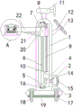
FIG. 1 is a schematic structural view of a street lamp convenient for maintenance and cleaning according to the present invention;
FIG. 2 is a top view of a street light post body connection structure in a street light structure convenient for maintenance and cleaning according to the present invention;
FIG. 3 is a front view of a connection structure of a lamp post body in a street lamp structure convenient for maintenance and cleaning according to the present invention;
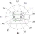
fig. 4 is an enlarged view of a portion a in fig. 1 of a street lamp convenient for maintenance and cleaning according to the present invention.
In the figure: the street lamp comprises a street lamp rod body 1, a movable shaft 2, a manual rocking handle 3, a first circumferential gear 4, a second circumferential gear 5, a threaded rod 6, a threaded block 7, a sliding block 8, a sliding rod 9, a fixed block 10, a wind power generation fan 11, a supporting rod 12, a solar panel 13, a driving box 14, a box body door 15, a rolling bearing 16, a street lamp base 17, a positioning screw 18, a cushion pad 19, a supporting frame 20, a movable block 21, a lighting lamp post 22, a movable block 23, a lighting lamp box 24, a diffuser 25, a transparent plate 26, a lighting lamp panel 27, a lighting lamp cannon 28, a driver 29, a heat dissipation aluminum sheet 30, a heat dissipation top seat 31, a heat dissipation pipe 32, a heat dissipation machine 33.
Detailed Description
The technical solutions in the embodiments of the present invention will be clearly and completely described below with reference to the drawings in the embodiments of the present invention, and it is obvious that the described embodiments are only a part of the embodiments of the present invention, and not all of the embodiments. All other embodiments, which can be derived by a person skilled in the art from the embodiments given herein without making any creative effort, shall fall within the protection scope of the present invention.
Referring to fig. 1-4, a street lamp convenient for maintenance and cleaning comprises a street lamp body 1, a movable shaft 2 is movably connected to the inner side of the street lamp body 1, a manual rocking handle 3 is fixedly connected to the right end of the movable shaft 2, a first circumferential gear 4 is fixedly connected to the left end of the movable shaft 2, a second circumferential gear 5 is meshed to the bottom of the first circumferential gear 4, a threaded rod 6 is fixedly connected to the inner side of the second circumferential gear 5, a threaded block 7 is connected to the outer side of the threaded rod 6 through a thread, a sliding block 8 is fixedly connected to the right side of the threaded block 7, a sliding rod 9 is fixedly connected to the inner top wall of the street lamp body 1, a fixed block 10 is fixedly connected to the right side wall of the street lamp body 1, a wind power generating fan 11 is fixedly connected to the top of the street lamp body 1, a support rod 12 is fixedly connected to the right side of the street lamp body, the right side of the driving box 14 is movably connected with a box body door 15, the top end and the bottom end of the threaded rod 6 are fixedly connected with rolling bearings 16, the bottom of the street lamp rod body 1 is fixedly connected with a street lamp base 17, the left side and the right side of the street lamp base 17 are respectively in threaded connection with positioning screws 18, the bottom of the street lamp base 17 is movably connected with a cushion pad 19, the left side of the threaded block 7 is fixedly connected with a support frame 20, the left side of the threaded block 7 is fixedly connected with a movable block 21, the left side of the movable block 21 is fixedly connected with a lighting lamp post 22, the right side of the lighting lamp post 22 is fixedly connected with a movable block 23, and the left end of the lighting lamp post 22 is fixedly connected with a lighting lamp box 24. when the lighting lamp box 24 needs to be maintained and cleaned, by rotating the manual crank 3, the movable shaft 2 and the first circumferential gear 4, therefore, the first circumferential gear 4 can drive the second circumferential gear 5 and the threaded rod 6 to rotate in sequence in the rotating process, the sliding rod 9 and the sliding hole can limit the threaded block 7 to rotate in a circumferential manner, and simultaneously, the up-and-down moving stability of the threaded block 7 can be improved, because the threaded block 7 is provided with a threaded hole matched with the outer thread of the threaded rod 6 on the inner side, and the threaded hole is in contact with the outer thread of the threaded rod 6 and generates displacement, the threaded rod 6 can drive the threaded block 7, the sliding block 8, the moving block 21, the lighting lamp post 22 and the lighting lamp box 24 to move downwards in sequence in the rotating process, the height of the lighting lamp box 24 can be reduced, a worker can directly clean dirt and dust above the lighting lamp box 24, the purpose of maintaining and cleaning the lighting lamp box 24 is realized, and the up-and down moving stability 2 of the lighting lamp post 22 can be improved by arranging, the support frame 20 is arranged to support the illuminating lamp post 22, the whole structure is simple, the aim of convenient maintenance and cleaning of the street lamp is achieved, when dirt and dust are stained on the upper portion of the street lamp to influence illumination, workers do not need to climb to the top end of the street lamp by means of a ladder to clean the street lamp, the safety of the workers is guaranteed, and the labor intensity of the workers is reduced, the bottom of the illuminating lamp box 24 is fixedly connected with the light scattering cover 25, the bottom of the illuminating lamp box 24 is fixedly connected with the transparent plate 26, the inner side of the illuminating lamp box 24 is fixedly connected with the illuminating lamp plate 27, the bottom of the illuminating lamp plate 27 is fixedly connected with the illuminating lamp cannon 28, the top of the illuminating lamp plate 27 is fixedly connected with the driver 29, the model of the driver 29 can be XH-LED, the left side and the right side of the driver 29 are both fixedly, the top of the lighting lamp box 24 is fixedly connected with the radiating pipes 32, the right side wall of the lighting lamp box 24 is fixedly connected with the radiating machine 33, the model of the radiating machine 33 can be M-X6, the top of the lighting lamp box 24 is fixedly connected with the fixing rod 34, cold air can be blown into the inner side of the lighting lamp box 24 by arranging the radiating machine 33, the inner side of the lighting lamp box 24 can be cooled by the circulating flow of the cold air in the inner side of the lighting lamp box 24, so that the driver 29 can be radiated, the purpose of street lamp radiating is realized, the heat of the driver 29 can be dispersed by arranging six radiating aluminum sheets 30 and a radiating top seat 31, the radiating effect of the driver 29 is improved, the inner side of the lighting lamp box 24 can be ventilated by arranging the two radiating pipes 32, the radiating effect of the street lamp is ensured, the service life of the street lamp is prolonged, through setting up four set screw 18 and cushion 19, can improve the stability that street lamp base 17 and ground are connected, through setting up drive box 14, can protect manual rocking handle 3, through setting up solar panel 13, can utilize solar energy to supply power to the street lamp, through setting up wind power generation fan 11, can utilize wind energy to supply power to the street lamp, the utilization ratio of resource has been improved, overall structure is simple, and the convenience is used, the radiating purpose of street lamp has been realized, can maintain the street lamp, the availability factor and the result of use of street lamp have been improved, the top fixedly connected with protection casing 35 of dead lever 34.
In the invention, the top end of the threaded rod 6 sequentially penetrates through the rolling bearing 16, the street lamp rod body 1, the second circumferential gear 5 and the threaded block 7 and extends to the inner side of the rolling bearing 16, and the top of the protective cover 35 is an inclined plane.
In the invention, the inner side of the thread block 7 is provided with a threaded hole matched with the outer thread of the threaded rod 6, the inner side of the sliding block 8 is provided with a sliding hole with the same diameter as that of the sliding rod 9, and the sliding hole is connected with the sliding rod 9 in a sliding manner.
In the invention, a movable long groove is formed in the left side of a street lamp pole body 1, a movable block 21 and a support frame 20 are both connected with the movable long groove in a sliding manner, and the support frame 20 is fixedly connected with a lighting lamp pole 22.
In the invention, the left side of the street lamp pole body 1 is provided with two sliding long grooves, the number of the sliding long grooves and the number of the movable blocks 23 are two, the movable blocks 23 and the sliding long grooves are T-shaped, and the two movable blocks 23 are respectively connected with the two sliding long grooves in a sliding manner.
In the invention, the left end of the movable shaft 2 sequentially penetrates through the street lamp rod body 1 and the first circumferential gear 4 and extends to the inner side of the first circumferential gear 4, and the manual rocking handle 3 is positioned at the inner side of the driving box 14.
In the invention, the number of the radiating pipes 32 is two, the two radiating pipes 32 are both communicated with the lighting lamp box 24, the lighting lamp bulbs 28 are uniformly distributed at the bottom of the lighting lamp panel 27, and the number of the radiating aluminum sheets 30 is six.
In the invention, the bottom ends of the positioning screws 18 sequentially penetrate through the street lamp base 17 and the buffer cushion 19 and extend to the lower part of the buffer cushion 19 to be connected with the ground, and the number of the positioning screws 18 is four.
In the invention, the rolling bearing 16 consists of an inner ring, a ball and an outer ring, wherein the inner ring is fixedly connected with the threaded rod 6, the outer ring is fixedly connected with the street lamp rod body 1, and the fixed block 10 is fixedly connected with the sliding rod 9.
When using, can blow in the inboard of lighting lamp box 24 with cold wind through setting up heat radiator 33, flow at the inboard circulation of lighting lamp box 24 through cold wind, can cool down the inboard of lighting lamp box 24, thereby can dispel the heat to driver 29, the radiating purpose of street lamp has been realized, through setting up six heat dissipation aluminum sheets 30 and heat dissipation footstock 31, can disperse the heat of driver 29, the radiating effect of driver 29 has been improved, through setting up two cooling tubes 32, can ventilate the inboard of lighting lamp box 24, guarantee the radiating effect of street lamp, the life of street lamp has been improved, the purpose of street lamp maintenance has been realized.
In summary, in the street lamp convenient for maintenance and cleaning, the heat radiator 33 is arranged to blow cold air into the inner side of the lighting lamp box 24, the inner side of the lighting lamp box 24 can be cooled through the circulation flow of the cold air in the inner side of the lighting lamp box 24, so that the driver 29 can be cooled, the purpose of street lamp heat dissipation is achieved, the heat of the driver 29 can be dispersed through the arrangement of the six heat-dissipating aluminum sheets 30 and the heat-dissipating top seat 31, the heat-dissipating effect of the driver 29 is improved, the ventilation can be performed on the inner side of the lighting lamp box 24 through the arrangement of the two heat-dissipating pipes 32, the heat-dissipating effect of the street lamp is ensured, the service life of the street lamp is prolonged, the purpose of street lamp maintenance is achieved, the stability of the connection between the street lamp base 17 and the ground can be improved through the arrangement of the four positioning screws 18 and the buffer cushions 19, through setting up solar panel 13, can utilize solar energy to supply power to the street lamp, through setting up aerogenerator fan 11, can utilize the wind energy to supply power to the street lamp, improved the utilization ratio of resource, overall structure is simple, facilitates the use, has realized the radiating purpose of street lamp, can maintain the street lamp, has improved the availability factor and the result of use of street lamp.
Moreover, when the lighting lamp box 24 needs to be maintained and cleaned, the manual crank 3 is rotated, the movable shaft 2 and the first circumferential gear 4 are sequentially driven to rotate in the rotating process of the manual crank 3, the first circumferential gear 4 is meshed with the second circumferential gear 5, the second circumferential gear 5 and the threaded rod 6 are sequentially driven to rotate in the rotating process of the first circumferential gear 4, the threaded block 7 can be limited to rotate circumferentially by arranging the sliding rod 9 and the sliding hole, the stability of up-and-down movement of the threaded block 7 can be improved, the threaded block 7 is provided with a threaded hole matched with the outer thread of the threaded rod 6 on the inner side, the threaded hole is contacted with the outer thread of the threaded rod 6 and generates displacement, and the threaded block 7, the sliding block 8, the movable block 21, the lighting lamp pole 22 and the lighting lamp box 24 are sequentially driven to move downwards in the rotating process of the threaded rod 6, the height of the lighting lamp box 24 can be reduced, workers can directly clean stains and dust above the lighting lamp box 24, the purpose of maintaining and cleaning the lighting lamp box 24 is achieved, the stability of up-down movement 2 of the lighting lamp pole 22 can be improved by arranging the movable block 23 and the sliding long groove, the lighting lamp pole 22 can be supported by arranging the support frame 20, the whole structure is simple, the purpose of facilitating maintenance and cleaning of the street lamp is achieved, when the stains and dust are adhered to the upper portion of the street lamp to affect illumination, the workers do not need to climb to the top end of the street lamp by virtue of a ladder to clean the street lamp, the safety of the workers is ensured, the labor intensity of the workers is reduced, the defect that the existing street lamp is inconvenient to maintain and clean is solved, when the stains and dust are adhered to the upper portion of the street lamp to affect illumination, the workers need to climb to the top end of the street lamp by virtue of the ladder to clean the street lamp, the method is time-consuming and labor-consuming, has certain dangerousness, cannot ensure the safety of workers, improves the labor intensity of the workers, is inconvenient to use, and reduces the use efficiency and the use effect of the street lamp.
It is to be noted that the terms "comprises," "comprising," or any other variation thereof, are intended to cover a non-exclusive inclusion, such that a process, method, article, or apparatus that comprises a list of elements does not include only those elements but may include other elements not expressly listed or inherent to such process, method, article, or apparatus. Without further limitation, an element defined by the phrase "comprising an … …" does not exclude the presence of other identical elements in a process, method, article, or apparatus that comprises the element.
Although embodiments of the present invention have been shown and described, it will be appreciated by those skilled in the art that changes, modifications, substitutions and alterations can be made in these embodiments without departing from the principles and spirit of the invention, the scope of which is defined in the appended claims and their equivalents.
Claims (9)
1. The utility model provides a street lamp convenient to maintain clearance, includes the street lamp body of rod (1), its characterized in that: the street lamp comprises a street lamp body (1), a movable shaft (2) is movably connected to the inner side of the street lamp body (1), a manual rocking handle (3) is fixedly connected to the right end of the movable shaft (2), a first circumferential gear (4) is fixedly connected to the left end of the movable shaft (2), a second circumferential gear (5) is meshed to the bottom of the first circumferential gear (4), a threaded rod (6) is fixedly connected to the inner side of the second circumferential gear (5), a threaded block (7) is connected to the outer side of the threaded rod (6) in a threaded manner, a sliding block (8) is fixedly connected to the right side of the threaded block (7), a sliding rod (9) is fixedly connected to the inner top wall of the street lamp body (1), a fixed block (10) is fixedly connected to the right side wall of the street lamp body (1), a wind power generator (11) is fixedly connected to the top of the street lamp body (1), and, the solar street lamp comprises a supporting rod (12), a solar panel (13), a driving box (14), a box door (15), rolling bearings (16), a street lamp base (17), positioning screws (18), cushion pads (19), a supporting frame (20), a moving block (21), a lighting lamp post (22), a moving block (23), a supporting frame (21), a supporting frame (23), a lamp post (22), a driving rod body (1), a box door (15), a rolling bearing (16), a positioning screw (18), a supporting frame and a supporting frame, wherein the right end of the supporting rod (12) is fixedly connected with the right end of the supporting rod (12), the right end of the street lamp post body (1) is fixedly connected with the right side of the driving box (14), the left side of the driving box (14) is movably connected with the box door, the top end and the bottom end of the threaded rod (6) are both fixedly, the left end fixedly connected with lighting lamp box (24) of illumination lamp pole (22), the bottom fixedly connected with light scattering shade (25) of lighting lamp box (24), the bottom fixedly connected with transparent plate (26) of lighting lamp box (24), the inboard fixedly connected with illumination lamp plate (27) of lighting lamp box (24), the bottom fixedly connected with illumination lamp cannon (28) of illumination lamp plate (27), the top fixedly connected with driver (29) of illumination lamp plate (27), the equal fixedly connected with heat dissipation aluminum sheet (30) of the left and right sides of driver (29), the top fixedly connected with heat dissipation footstock (31) of driver (29), the top fixedly connected with heat dissipation pipe (32) of lighting lamp box (24), the right side wall fixedly connected with heat dissipation machine (33) of lighting lamp box (24), the top fixedly connected with dead lever (34) of lighting lamp box (24), the top end of the fixed rod (34) is fixedly connected with a protective cover (35).
2. The street lamp convenient for maintenance and cleaning as claimed in claim 1, wherein: the top of threaded rod (6) runs through antifriction bearing (16), the street lamp body of rod (1), second circumference gear (5) and screw block (7) in proper order and extends to the inboard of antifriction bearing (16), the top of protection casing (35) is the inclined plane.
3. The street lamp convenient for maintenance and cleaning as claimed in claim 1, wherein: the threaded hole that matches with threaded rod (6) outside screw thread looks adaptation is seted up to the inboard of screw thread piece (7), the sliding hole that equals with slide bar (9) diameter is seted up to the inboard of sliding block (8), and sliding hole and slide bar (9) sliding connection.
4. The street lamp convenient for maintenance and cleaning as claimed in claim 1, wherein: the left side of the street lamp pole body (1) is provided with a movable long groove, the movable block (21) and the support frame (20) are both in sliding connection with the movable long groove, and the support frame (20) is fixedly connected with a lighting lamp pole (22).
5. The street lamp convenient for maintenance and cleaning as claimed in claim 1, wherein: the left side of the street lamp pole body (1) is provided with two sliding long grooves, the number of the sliding long grooves and the number of the movable blocks (23) are two, the movable blocks (23) and the sliding long grooves are T-shaped, and the two movable blocks (23) are respectively connected with the two sliding long grooves in a sliding mode.
6. The street lamp convenient for maintenance and cleaning as claimed in claim 1, wherein: the left end of loose axle (2) runs through the street lamp body of rod (1) and first circumference gear (4) in proper order and extends to the inboard of first circumference gear (4), manual rocking handle (3) are located the inboard of drive box (14).
7. The street lamp convenient for maintenance and cleaning as claimed in claim 1, wherein: the quantity of cooling tube (32) is two, two cooling tube (32) all are linked together with lighting lamp box (24), lighting lamp big gun (28) are in the bottom evenly distributed of illumination lamp plate (27), the quantity of heat dissipation aluminum sheet (30) is six.
8. The street lamp convenient for maintenance and cleaning as claimed in claim 1, wherein: the bottom end of each positioning screw (18) penetrates through the street lamp base (17) and the buffer cushion (19) in sequence and extends to the lower part of the buffer cushion (19) to be connected with the ground, and the number of the positioning screws (18) is four.
9. The street lamp convenient for maintenance and cleaning as claimed in claim 1, wherein: the rolling bearing (16) is composed of an inner ring, a rolling ball and an outer ring, the inner ring is fixedly connected with the threaded rod (6), the outer ring is fixedly connected with the street lamp rod body (1), and the fixing block (10) is fixedly connected with the sliding rod (9).
Priority Applications (1)
| Application Number | Priority Date | Filing Date | Title |
|---|---|---|---|
| CN202010863829.XA CN112128687A (en) | 2020-08-25 | 2020-08-25 | Street lamp convenient to maintain clearance |
Applications Claiming Priority (1)
| Application Number | Priority Date | Filing Date | Title |
|---|---|---|---|
| CN202010863829.XA CN112128687A (en) | 2020-08-25 | 2020-08-25 | Street lamp convenient to maintain clearance |
Publications (1)
| Publication Number | Publication Date |
|---|---|
| CN112128687A true CN112128687A (en) | 2020-12-25 |
Family
ID=73848533
Family Applications (1)
| Application Number | Title | Priority Date | Filing Date |
|---|---|---|---|
| CN202010863829.XA Pending CN112128687A (en) | 2020-08-25 | 2020-08-25 | Street lamp convenient to maintain clearance |
Country Status (1)
| Country | Link |
|---|---|
| CN (1) | CN112128687A (en) |
Cited By (3)
| Publication number | Priority date | Publication date | Assignee | Title |
|---|---|---|---|---|
| CN113587030A (en) * | 2021-07-27 | 2021-11-02 | 江苏嘉亿照明科技有限公司 | Solar energy lighting lamp |
| CN114034002A (en) * | 2021-11-30 | 2022-02-11 | 湖南劲点新能源科技有限责任公司 | LED street lamp convenient to equipment is maintained |
| CN117628453A (en) * | 2024-01-12 | 2024-03-01 | 浙江派威数字技术有限公司 | High heat dissipation LED lamps and lanterns |
Citations (5)
| Publication number | Priority date | Publication date | Assignee | Title |
|---|---|---|---|---|
| CN207921929U (en) * | 2018-03-22 | 2018-09-28 | 邓家伟 | A kind of LED illumination lamp that facilitating dedusting and can radiate |
| CN208058684U (en) * | 2018-03-07 | 2018-11-06 | 泉州市世纪新创工业设计有限公司 | A kind of solar street light dust-extraction unit |
| CN208170234U (en) * | 2018-03-27 | 2018-11-30 | 张瑞泉 | A kind of solar street light being convenient to clean |
| CN210662657U (en) * | 2019-10-31 | 2020-06-02 | 宿迁东奥照明有限公司 | Energy-saving telescopic solar street lamp |
| CN211260605U (en) * | 2019-08-23 | 2020-08-14 | 宜宾市华烽节能设备有限公司 | Solar street lamp convenient to change and maintain LED lamp |
-
2020
- 2020-08-25 CN CN202010863829.XA patent/CN112128687A/en active Pending
Patent Citations (5)
| Publication number | Priority date | Publication date | Assignee | Title |
|---|---|---|---|---|
| CN208058684U (en) * | 2018-03-07 | 2018-11-06 | 泉州市世纪新创工业设计有限公司 | A kind of solar street light dust-extraction unit |
| CN207921929U (en) * | 2018-03-22 | 2018-09-28 | 邓家伟 | A kind of LED illumination lamp that facilitating dedusting and can radiate |
| CN208170234U (en) * | 2018-03-27 | 2018-11-30 | 张瑞泉 | A kind of solar street light being convenient to clean |
| CN211260605U (en) * | 2019-08-23 | 2020-08-14 | 宜宾市华烽节能设备有限公司 | Solar street lamp convenient to change and maintain LED lamp |
| CN210662657U (en) * | 2019-10-31 | 2020-06-02 | 宿迁东奥照明有限公司 | Energy-saving telescopic solar street lamp |
Cited By (4)
| Publication number | Priority date | Publication date | Assignee | Title |
|---|---|---|---|---|
| CN113587030A (en) * | 2021-07-27 | 2021-11-02 | 江苏嘉亿照明科技有限公司 | Solar energy lighting lamp |
| CN114034002A (en) * | 2021-11-30 | 2022-02-11 | 湖南劲点新能源科技有限责任公司 | LED street lamp convenient to equipment is maintained |
| CN117628453A (en) * | 2024-01-12 | 2024-03-01 | 浙江派威数字技术有限公司 | High heat dissipation LED lamps and lanterns |
| CN117628453B (en) * | 2024-01-12 | 2024-10-22 | 浙江派威数字技术有限公司 | High heat dissipation LED lamps and lanterns |
Similar Documents
| Publication | Publication Date | Title |
|---|---|---|
| CN212081085U (en) | Waterproof nature LED street lamp of high leakproofness | |
| CN207621722U (en) | A floodlight with adjustable angle | |
| CN217402433U (en) | Efficient and energy-saving LED projection lamp | |
| RU166928U1 (en) | LED LAMP | |
| CN201909294U (en) | Heat radiation assembly structure of light emitting diode (LED) street lamp | |
| CN216047184U (en) | Simple modular LED spotlight | |
| CN212746132U (en) | Projecting lamp that outdoor type security is good | |
| CN213453345U (en) | Heat dissipation type projecting lamp | |
| CN220355366U (en) | Novel garden lamp | |
| CN208886624U (en) | A kind of road LED light with antifogging action | |
| CN202302899U (en) | Large-power light-emitting diode (LED) lamp | |
| CN208951935U (en) | A kind of LED street lamp facilitating heat dissipation | |
| CN219797131U (en) | LED projecting lamp with regulatory function | |
| CN223105995U (en) | A floodlight with adjustable irradiation angle | |
| CN222316760U (en) | Outdoor high-pole lighting lamp | |
| CN214038025U (en) | LED (light-emitting diode) illuminating lamp | |
| CN223435127U (en) | Waterproof energy-saving lamps | |
| CN207298759U (en) | A kind of road lamp with information of vehicles identification | |
| CN222316920U (en) | LED lamp with heat dissipation structure | |
| CN213146233U (en) | Projecting lamp that has heat radiation structure convenient to angle is shone in regulation | |
| CN214890863U (en) | Novel solar street lamp | |
| CN211526292U (en) | Remote control wind power generation street lamp | |
| CN212510917U (en) | An IoT low-light energy landscape light | |
| CN118836402B (en) | Lampshade and street lamp | |
| CN219811307U (en) | Energy-saving luminous guide signboard |
Legal Events
| Date | Code | Title | Description |
|---|---|---|---|
| PB01 | Publication | ||
| PB01 | Publication | ||
| SE01 | Entry into force of request for substantive examination | ||
| SE01 | Entry into force of request for substantive examination | ||
| RJ01 | Rejection of invention patent application after publication | ||
| RJ01 | Rejection of invention patent application after publication |
Application publication date: 20201225 |