CN112123649A - Bellows production water-cooling circulating device - Google Patents
Bellows production water-cooling circulating device Download PDFInfo
- Publication number
- CN112123649A CN112123649A CN202010822358.8A CN202010822358A CN112123649A CN 112123649 A CN112123649 A CN 112123649A CN 202010822358 A CN202010822358 A CN 202010822358A CN 112123649 A CN112123649 A CN 112123649A
- Authority
- CN
- China
- Prior art keywords
- pipe
- water
- cooling
- water tank
- cooling water
- Prior art date
- Legal status (The legal status is an assumption and is not a legal conclusion. Google has not performed a legal analysis and makes no representation as to the accuracy of the status listed.)
- Granted
Links
- 238000001816 cooling Methods 0.000 title claims abstract description 53
- 238000004519 manufacturing process Methods 0.000 title claims abstract description 22
- XLYOFNOQVPJJNP-UHFFFAOYSA-N water Substances O XLYOFNOQVPJJNP-UHFFFAOYSA-N 0.000 claims abstract description 121
- 239000000498 cooling water Substances 0.000 claims abstract description 79
- 239000007921 spray Substances 0.000 claims abstract description 11
- 230000017525 heat dissipation Effects 0.000 claims description 20
- 239000000428 dust Substances 0.000 claims description 9
- 230000007246 mechanism Effects 0.000 claims description 6
- 230000005540 biological transmission Effects 0.000 claims description 4
- 238000005265 energy consumption Methods 0.000 abstract description 5
- 238000005457 optimization Methods 0.000 description 8
- 238000009434 installation Methods 0.000 description 5
- 230000000694 effects Effects 0.000 description 4
- 238000000034 method Methods 0.000 description 4
- 230000009471 action Effects 0.000 description 3
- 238000012423 maintenance Methods 0.000 description 2
- 230000008569 process Effects 0.000 description 2
- 230000005855 radiation Effects 0.000 description 2
- 230000009467 reduction Effects 0.000 description 2
- 238000007493 shaping process Methods 0.000 description 2
- 238000005507 spraying Methods 0.000 description 2
- 230000004075 alteration Effects 0.000 description 1
- 230000009286 beneficial effect Effects 0.000 description 1
- 230000007547 defect Effects 0.000 description 1
- 238000001704 evaporation Methods 0.000 description 1
- 230000008020 evaporation Effects 0.000 description 1
- 238000010438 heat treatment Methods 0.000 description 1
- 238000009776 industrial production Methods 0.000 description 1
- 238000012986 modification Methods 0.000 description 1
- 230000004048 modification Effects 0.000 description 1
- 230000000630 rising effect Effects 0.000 description 1
- 239000004576 sand Substances 0.000 description 1
- 239000000779 smoke Substances 0.000 description 1
- 238000006467 substitution reaction Methods 0.000 description 1
- 210000003781 tooth socket Anatomy 0.000 description 1
Images


Classifications
-
- B—PERFORMING OPERATIONS; TRANSPORTING
- B29—WORKING OF PLASTICS; WORKING OF SUBSTANCES IN A PLASTIC STATE IN GENERAL
- B29C—SHAPING OR JOINING OF PLASTICS; SHAPING OF MATERIAL IN A PLASTIC STATE, NOT OTHERWISE PROVIDED FOR; AFTER-TREATMENT OF THE SHAPED PRODUCTS, e.g. REPAIRING
- B29C35/00—Heating, cooling or curing, e.g. crosslinking or vulcanising; Apparatus therefor
- B29C35/16—Cooling
-
- F—MECHANICAL ENGINEERING; LIGHTING; HEATING; WEAPONS; BLASTING
- F26—DRYING
- F26B—DRYING SOLID MATERIALS OR OBJECTS BY REMOVING LIQUID THEREFROM
- F26B13/00—Machines and apparatus for drying fabrics, fibres, yarns, or other materials in long lengths, with progressive movement
- F26B13/24—Arrangements of devices using drying processes not involving heating
- F26B13/28—Arrangements of devices using drying processes not involving heating for applying pressure; for brushing; for wiping
-
- F—MECHANICAL ENGINEERING; LIGHTING; HEATING; WEAPONS; BLASTING
- F26—DRYING
- F26B—DRYING SOLID MATERIALS OR OBJECTS BY REMOVING LIQUID THEREFROM
- F26B5/00—Drying solid materials or objects by processes not involving the application of heat
- F26B5/14—Drying solid materials or objects by processes not involving the application of heat by applying pressure, e.g. wringing; by brushing; by wiping
-
- B—PERFORMING OPERATIONS; TRANSPORTING
- B29—WORKING OF PLASTICS; WORKING OF SUBSTANCES IN A PLASTIC STATE IN GENERAL
- B29C—SHAPING OR JOINING OF PLASTICS; SHAPING OF MATERIAL IN A PLASTIC STATE, NOT OTHERWISE PROVIDED FOR; AFTER-TREATMENT OF THE SHAPED PRODUCTS, e.g. REPAIRING
- B29C35/00—Heating, cooling or curing, e.g. crosslinking or vulcanising; Apparatus therefor
- B29C35/16—Cooling
- B29C2035/1616—Cooling using liquids
-
- B—PERFORMING OPERATIONS; TRANSPORTING
- B29—WORKING OF PLASTICS; WORKING OF SUBSTANCES IN A PLASTIC STATE IN GENERAL
- B29L—INDEXING SCHEME ASSOCIATED WITH SUBCLASS B29C, RELATING TO PARTICULAR ARTICLES
- B29L2031/00—Other particular articles
- B29L2031/703—Bellows
Landscapes
- Engineering & Computer Science (AREA)
- Health & Medical Sciences (AREA)
- Mechanical Engineering (AREA)
- General Engineering & Computer Science (AREA)
- Life Sciences & Earth Sciences (AREA)
- Molecular Biology (AREA)
- Physics & Mathematics (AREA)
- Oral & Maxillofacial Surgery (AREA)
- Thermal Sciences (AREA)
- Textile Engineering (AREA)
Abstract
The invention discloses a water-cooling circulating device for corrugated pipe production, which relates to the technical field of water-cooling circulation and comprises a cooling water tank and a water chiller, wherein a spray pipe communicated with the water chiller is arranged in the cooling water tank, a steam collecting cover is arranged above the cooling water tank, the top of the steam collecting cover is communicated with an exhaust return pipe arranged outdoors through a communicating pipe, annular radiating fins are arranged on the surface of the exhaust return pipe and the surface of the outdoor part of the communicating pipe, and a ground cooling water tank is arranged below the ground at the bottom of the cooling water tank. The invention solves the problem that the cooling water and the electric energy consumption are higher because the cooling water tank and the water cooler are only adopted to cool and circulate the cooling water when the cooling water tank for producing the traditional corrugated pipe is used by arranging the steam collecting cover, the exhaust return pipe, the ground cooling water tank, the air inlet pipe, the air outlet pipe, the rotary drum, the sponge wiper and the water collecting tank.
Description
Technical Field
The invention relates to the technical field of water-cooling circulation, in particular to a water-cooling circulation device for corrugated pipe production.
Background
The bellows need be cooled down its form through the cooling link after the production shaping, and the bellows is in industrial production, and common heat sink is cooling tank water-cooling, gets into from cooling tank's one end after the bellows shaping, has the shower to carry out the water spray cooling to the surface of bellows in cooling tank, then stretches out from cooling tank's the other end, can accomplish the cooling step.
Traditional bellows production usefulness's cooling trough is when using, only adopt cooling trough and cold water machine to cool down and circulate to the cooling water usually, cool down to the bellows with this, however, the circulating water directly sprays the surface at the bellows, spill water and water smoke easily, bellows surface temperature is higher when adding just cooling, cause the circulating water evaporation easily, a lot of cooling water of surface adhesion when coming out from cooling trough after the bellows cooling, lead to not only causing the work ground moist, and can lead to cooling water consumption serious, furthermore, summer room temperature is high working environment temperature, the cooling water set cools down alone and causes cooling water set high load operation, lead to cooling water set high strength work reduction life, the cooling effect descends, power consumption is serious.
Disclosure of Invention
Technical problem to be solved
Aiming at the defects of the prior art, the invention provides a water-cooling circulating device for corrugated pipe production, which solves the problem that cooling water and electric energy consumption are high because the cooling water tank and a water cooler are generally only adopted to cool and circulate the cooling water when a cooling water tank for the traditional corrugated pipe production is used.
(II) technical scheme
In order to achieve the purpose, the invention provides the following technical scheme: the utility model provides a bellows production water-cooling circulating device, includes cooling trough and cold water machine, be provided with the shower that is linked together with the cold water machine in the cooling trough, the top of cooling trough is provided with steam and collects the cover, the top that the cover was collected to steam is linked together through setting up communicating pipe and setting up at outdoor exhaust-return pipe, the surface of exhaust-return pipe and the surface that communicating pipe is located outdoor part are provided with annular fin.
The utility model discloses a cooling water tank, including cooling trough, ground cold water groove, air inlet pipe and exhaust hood, the ground cold water groove of cooling trough bottom's ground below is provided with the ground cold water groove, the ground cold water groove is that the double-walled is cylindric, the outer wall surface circumference of ground cold water groove is provided with the heating panel, the vertical direction in both sides in ground cold water groove is provided with the heat dissipation curb plate, the both ends of ground cold water inslot wall are connected with the air-supply line respectively and go out the tuber pipe, the air inlet of air-supply line and the air outlet that goes out the tuber pipe all extend to outdoor ground above and are linked together with collection tuber pipe and exhaust.
The bottom of the cooling water tank is communicated with the top of the ground cooling water tank through a water outlet pipe, the water outlet end of a first water inlet pipe arranged in the ground cooling water tank penetrates through the ground cooling water tank and is communicated with the water inlet of the water cooler, the water outlet of the water cooler is communicated with a spray pipe through a second water inlet pipe, and a pressure pump is arranged between the spray pipe and the second water inlet pipe.
The cooling water tank is rotatably connected with a rotary drum corresponding to the cooled extending end of the corrugated pipe, a driving mechanism in transmission connection with the rotary drum is arranged on the cooling water tank, a sponge wiper is arranged inside the rotary drum, a water channel is arranged on the inner wall of the rotary drum, a water collecting tank is arranged on the surface of the rotary drum at a position corresponding to the water channel, and water outlets are formed in the bottoms of the exhaust return pipe and the water collecting tank.
Preferably, the distance between the steam collection cover and the cooling water tank is 0.3-0.5 m, and an active exhaust fan is arranged between the communicating pipe and the steam collection cover.
Preferably, the air outlet of the exhaust return pipe is horizontally arranged, and the air outlet of the exhaust return pipe is provided with a passive exhaust fan.
Preferably, the heat dissipation plates are arranged at equal intervals and are parallel to each other, and the bottom of each heat dissipation plate is horizontal and the top of each heat dissipation plate is arc-shaped.
Preferably, the inner diameter of the air inlet pipe is smaller than the inner diameter of the air outlet of the air inlet pipe, the inner diameters of all the positions of the air outlet pipe are equal, and the inner diameter of the air outlet pipe is at least 2 times of the inner diameter of the air inlet pipe.
Preferably, the air collecting pipe is a group of pipelines which are arranged in an annular array by taking an air inlet of the air inlet pipe as the center, and the air inlet of the air collecting pipe is horizontally arranged and provided with a dust screen.
Preferably, the exhaust hood includes that the top is the rain cover of hollow circular cone, sets up the kuppe that is hollow inverted cone below the rain cover and sets up the cylinder dust cover between kuppe and play tuber pipe, kuppe and the coaxial setting of kuppe, and the external diameter of the rain cover is greater than kuppe external diameter 0.1 meter at least.
Preferably, the inner wall of the rotary drum is provided with a mounting groove for mounting the sponge wiper, the mounting groove is communicated with one end of the rotary drum, one end of the rotary drum is provided with a baffle ring through a screw, one side of the baffle ring, which is close to the sponge wiper, is provided with a baffle rod, the baffle rod is inserted into the mounting groove, and the baffle rod is contacted with the opposite end of the sponge wiper.
Preferably, the sponge wiper is a sponge block provided with a plastic base, a through hole is formed in the plastic base, and the water channel is communicated with the mounting groove.
(III) advantageous effects
The invention provides a water-cooling circulating device for corrugated pipe production, which has the following beneficial effects:
according to the invention, the steam collecting cover, the exhaust backflow pipe, the ground cold water tank, the air inlet pipe, the air outlet pipe, the rotary drum, the sponge wiper and the water collecting tank are arranged, the steam collecting cover and the exhaust backflow pipe can collect water vapor and backflow water liquefied by water vapor, the rotary drum can collect most of water on the surface of the corrugated pipe after cooling through the sponge wiper and the water collecting tank in a rotating manner, the backflow water can be recycled, the moisture phenomenon of a working environment can be improved, and water resources can be saved; except that the cold water machine can cool down the cooling water, through the air-supply line, go out tuber pipe and ground cold water tank and carry out the nature cooling to the cooling water, it is the operational environment temperature when the temperature is higher to improve summer, can also share the job task reduction energy consumption of cold water machine, reach protection cold water machine and energy-conserving effect, reduce production and maintenance cost, energy-concerving and environment-protective, the cooling water tank of having solved traditional bellows production usefulness is when using, only adopt cooling water tank and cold water machine to cool down and circulate to the cooling water usually, lead to the higher problem of cooling water and electric energy consumption.
Drawings
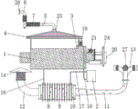
FIG. 1 is a schematic view of the overall structure of the present invention;
FIG. 2 is a front cross-sectional view of the drum of the present invention in position;
FIG. 3 is a side cross-sectional view of the sump of the present invention;
FIG. 4 is a front cross-sectional view of the active exhaust fan of the present invention;
FIG. 5 is a front cross-sectional view of the exhaust hood of the present invention;
FIG. 6 is a side view of a cold water tank according to the present invention;
FIG. 7 is a front view of the air collecting duct of the present invention;
fig. 8 is a top view of the air collecting duct of the present invention.
In the figure: 1. a cooling water tank; 2. a water chiller; 3. a shower pipe; 4. a steam collection hood; 5. a communicating pipe; 6. an exhaust gas return pipe; 7. a heat sink; 8. a ground cold water tank; 9. a heat dissipation plate; 10. a heat dissipation side plate; 11. an air inlet pipe; 12. an air outlet pipe; 13. an air collecting pipe; 14. an exhaust hood; 141. a rain shield; 142. a pod; 143. a dust cover; 15. an air-cooling sheet; 16. a water outlet pipe; 17. a first water inlet pipe; 18. a water inlet pipe II; 19. a pressure pump; 20. a rotating drum; 21. a drive mechanism; 22. a sponge wiper; 23. a water passage; 24. a water collection tank; 25. an active exhaust fan; 26. a passive exhaust fan; 27. a dust screen; 28. mounting grooves; 29. a baffle ring; 30. a stop lever.
Detailed Description
The technical solutions in the embodiments of the present invention will be clearly and completely described below with reference to the drawings in the embodiments of the present invention, and it is obvious that the described embodiments are only a part of the embodiments of the present invention, and not all of the embodiments. All other embodiments, which can be derived by a person skilled in the art from the embodiments given herein without making any creative effort, shall fall within the protection scope of the present invention.
As shown in fig. 1 to 8, the present invention provides a technical solution: the utility model provides a bellows production water-cooling circulating device, includes cooling trough 1 and cold water machine 2, is provided with the shower 3 that is linked together with cold water machine 2 in the cooling trough 1, and the top of cooling trough 1 is provided with steam collection cover 4, and the top of steam collection cover 4 is linked together through setting up communicating pipe 5 and setting up at outdoor exhaust-back flow 6, and the surface of exhaust-back flow 6 and the surface that communicating pipe 5 is located outdoor part are provided with annular fin 7.
The underground water tank 8 is arranged below the ground at the bottom of the cooling water tank 1, the underground water tank 8 is double-wall cylindrical, air in the air inlet pipe 11 penetrates through the center of the underground water tank 8 and is discharged from the air outlet pipe 12, cooling water in the underground water tank 8 is cooled through air cooling, cooling water near the center is cooled through land heat exchange, all cooling water is cooled through the water cooling machine 2, the heat dissipation plates 9 are circumferentially arranged on the surface of the outer wall of the underground water tank 8, heat dissipation side plates 10 are arranged in the vertical direction of two sides of the underground water tank 8, two ends of the inner wall of the underground water tank 8 are respectively connected with the air inlet pipe 11 and the air outlet pipe 12, an air inlet of the air inlet pipe 11 and an air outlet of the air outlet pipe 12 extend to the ground above the outdoor ground and are respectively communicated with the air collecting pipe 13 and the exhaust hood 14, and axial air cooling fins 15 are arranged inside the inner wall of the cooling water tank 1 and on the.
The bottom of the cooling water tank 1 is communicated with the top of the ground cooling water tank 8 through a water outlet pipe 16, the water outlet end of a water inlet pipe I17 arranged inside the ground cooling water tank 8 penetrates through the ground cooling water tank 8 and is communicated with the water inlet of the water cooling machine 2, the water outlet of the water cooling machine 2 is communicated with the spray pipe 3 through a water inlet pipe II 18, a pressure pump 19 is arranged between the spray pipe 3 and the water inlet pipe II 18 to pressurize the cooling water for the second time, the cooling water is prevented from coming out of the ground cooling water tank 8 below the ground, the rising height is increased, and the spraying pressure is.
The cooling water tank 1 is rotatably connected with a rotary drum 20 corresponding to the cooled extension end of the corrugated pipe, a driving mechanism 21 in transmission connection with the rotary drum 20 is arranged on the cooling water tank 1, the driving mechanism 21 is a low-power motor, the rotary drum 20 can be driven to rotate only by driving the rotary drum 20 through a gear and tooth socket transmission of the outer wall of the rotary drum 20, a supporting plate fixedly connected to the cooling water tank 1 is arranged at the bottom of the rotary drum 20, the cooling water tank 1, the supporting plate and the rotary drum 20 are rotatably connected, the supporting plate is used for providing supporting force for the rotary drum 20, a sponge wiper 22 is arranged inside the rotary drum 20, a water channel 23 is arranged on the inner wall of the rotary drum 20, a water collecting tank 24 is arranged on the surface of the rotary drum 20 corresponding to the position of the water channel 23, the side view of the water collecting tank 24 is in a water droplet shape, water thrown out from the water channel 23 is intercepted by the water collecting tank 24, the exhaust return pipe 6 and the bottom of the water collecting tank 24 are both provided with water outlets.
As a technical optimization scheme of the invention, the distance between the steam collection cover 4 and the cooling water tank 1 is 0.3-0.5 m, so that steam can be effectively collected, meanwhile, enough distance is provided for facilitating internal maintenance, the active exhaust fan 25 is arranged between the communicating pipe 5 and the steam collection cover 4, the active exhaust fan 25 is provided with an independent power switch, and the active exhaust fan 25 is started to actively exhaust in windy weather or under the condition that the communicating pipe 5 and the exhaust backflow pipe 6 do not smoothly exhaust to cause external air backflow, so that smooth exhaust is ensured.
As a technical optimization scheme of the invention, the air outlet of the exhaust return pipe 6 is horizontally arranged, and the air outlet of the exhaust return pipe 6 is provided with the passive exhaust fan 26, so that hot air can be conveniently discharged, the installation needs to be carried out according to the prevailing wind direction of the installation place all the year round, the passive exhaust fan 26 is installed along the wind direction, and the wind blows the passive exhaust fan 26 to rotate, so that air is sucked to the outside of the exhaust return pipe 6.
As a technical optimization scheme of the invention, the heat dissipation plates 9 are arranged at equal intervals and are parallel to each other, the bottoms of the heat dissipation plates 9 are horizontal, the tops of the heat dissipation plates 9 are arc-shaped, the heat dissipation plates are placed on the ground before installation and are not easy to roll, the installation angle is convenient to determine when the heat dissipation plates are embedded, and sand and stones are convenient to contact with the surfaces of the heat dissipation plates 9 and the ground cooling water tank 8.
As a technical optimization scheme of the invention, the inner diameter of an air inlet pipe 11 is smaller than the inner diameter of an air outlet of the air inlet pipe 11, the inner diameters of all parts of an air outlet pipe 12 are equal, the density of hot air is small and rises, so that air flow is formed, the main wind direction of the local four seasons of the installation site needs to be considered when the air inlet pipe 11 and the air outlet pipe 12 are installed, the air inlet pipe 11 is installed in the upper wind direction of the air outlet pipe 12 relative to water, the inner diameter of the air outlet pipe 12 is at least 2 times of the inner diameter of the air inlet pipe 11, and the hot air can flow out of the air outlet pipe 12 more easily, so that the stable air flow direction.
As a technical optimization scheme of the invention, the wind collecting pipes 13 are a group of pipes which are arranged in an annular array by taking the air inlets of the air inlet pipes 11 as the centers, air can be fed from different directions, and the air inlets of the wind collecting pipes 13 are horizontally arranged and are provided with dust screens 27, so that garbage such as leaves and the like can be prevented from entering.
As a technical optimization scheme of the present invention, the exhaust hood 14 includes a rain shield 141 with a hollow conical top, a wind deflector 142 with a hollow inverted conical bottom disposed below the rain shield 141, and a cylindrical dust cover 143 disposed between the wind deflector 142 and the air outlet pipe 12, the wind deflector 142 and the rain shield 141 are coaxially disposed, and the outer diameter of the rain shield 141 is at least 0.1 m greater than the outer diameter of the wind deflector 142, so as to block rain and guide flow, and simultaneously effectively prevent rain from entering.
As a technical optimization scheme of the invention, the inner wall of the rotary drum 20 is provided with a mounting groove 28 for mounting the sponge wiper 22, the sponge wiper 22 can be disassembled and assembled along the mounting groove 28, the mounting groove 28 is communicated with one end of the rotary drum 20, one end of the rotary drum 20 is provided with a baffle ring 29 through screws, one side of the baffle ring 29 close to the sponge wiper 22 is provided with a baffle rod 30, the baffle rod 30 is inserted in the mounting groove 28, the baffle rod 30 is contacted with the opposite end of the sponge wiper 22, the sponge wiper 22 can be conveniently mounted, maintained and replaced through the baffle ring 29, and therefore the sponge wiper 22 can effectively absorb water on the surface of the corrugated pipe when the corrugated pipe comes out of one end of the cooling water tank 1.
As a technical optimization scheme of the invention, the sponge wiper 22 is a sponge block provided with a plastic base, a through hole is arranged on the plastic base, the water channel 23 is communicated with the mounting groove 28, the rotary drum 20 rotates, and water inside the sponge wiper 22 centrifugally moves and reaches the water collecting tank 24 through the mounting groove 28, the through hole and the water channel 23.
The working principle is as follows: the corrugated pipe enters from the left end of the cooling water tank 1 and extends out of the right end, the water cooler 2 and the booster pump 19 drive cooling water to reach the water cooler 2 from the ground cooling water tank 8 through the first water inlet pipe 17, and reach the spray pipe 3 through the second water inlet pipe 18 and the booster pump 19 after being cooled by the water cooler 2, the corrugated pipe is cooled by water through spraying of the spray pipe 3, and the sprayed water reaches the ground cooling water tank 8 through the water outlet pipe 16; outdoor air enters the air inlet pipe 11 through the air collecting pipe 13 and flows out through the ground cold water tank 8, the air outlet pipe 12 and the dust cover 143, and meanwhile, the ground cold water tank 8 radiates heat through the heat radiation plate 9, the heat radiation side plate 10 and the air cooling fins 15; the generated water vapor is discharged to the outside through the steam collecting cover 4, the communicating pipe 5 and the exhaust return pipe 6, and return water generated by liquefying the water vapor is stored at the bottom of the exhaust return pipe 6; the driving mechanism 21 drives the rotating drum 20 to rotate, the sponge wiper 22 in the rotating drum 20 wipes off accumulated water on the surface of the corrugated pipe, the accumulated water is collected by the water collecting tank 24 through the water channel 23, the accumulated water in the water collecting tank 24 and return water in the exhaust return pipe 6 flow back to the cooling water tank 1 through the water outlet connecting water pipe, and the heat dissipation effect is achieved through reciprocating circulation.
In conclusion, the steam collecting cover 4, the exhaust return pipe 6, the ground cooling water tank 8, the air inlet pipe 11, the air outlet pipe 12, the rotary drum 20, the sponge wiper 22 and the water collecting tank 24 are arranged, so that the problem that cooling water and electric energy consumption are high because the cooling water tank 1 and the water cooler 2 are only adopted to cool and circulate cooling water when the cooling water tank 1 for producing the traditional corrugated pipe is used is solved.
It is noted that, herein, relational terms such as first and second, and the like may be used solely to distinguish one entity or action from another entity or action without necessarily requiring or implying any actual such relationship or order between such entities or actions. Also, the terms "comprises," "comprising," or any other variation thereof, are intended to cover a non-exclusive inclusion, such that a process, method, article, or apparatus that comprises a list of elements does not include only those elements but may include other elements not expressly listed or inherent to such process, method, article, or apparatus.
Although embodiments of the present invention have been shown and described, it will be appreciated by those skilled in the art that changes, modifications, substitutions and alterations can be made in these embodiments without departing from the principles and spirit of the invention, the scope of which is defined in the appended claims and their equivalents.
Claims (9)
1. The utility model provides a bellows production water-cooling circulating device, includes cooling trough (1) and cold water machine (2), be provided with shower (3) that are linked together with cold water machine (2) in cooling trough (1), its characterized in that: a steam collecting cover (4) is arranged above the cooling water tank (1), the top of the steam collecting cover (4) is communicated with an exhaust return pipe (6) arranged outdoors through a communicating pipe (5), and annular radiating fins (7) are arranged on the surface of the exhaust return pipe (6) and the surface of the outdoor part of the communicating pipe (5);
a ground cooling water tank (8) is arranged below the ground at the bottom of the cooling water tank (1), the ground cooling water tank (8) is in a double-wall cylindrical shape, heat dissipation plates (9) are circumferentially arranged on the surface of the outer wall of the ground cooling water tank (8), heat dissipation side plates (10) are vertically arranged on two sides of the ground cooling water tank (8), an air inlet pipe (11) and an air outlet pipe (12) are respectively connected to two ends of the inner wall of the ground cooling water tank (8), air inlets of the air inlet pipe (11) and air outlets of the air outlet pipe (12) extend to the ground above the outside and are respectively communicated with an air collecting pipe (13) and an exhaust hood (14), and axial air cooling fins (15) are respectively arranged inside the inner wall of the cooling water tank (1) and on the inner walls of the air inlet pipe (11) and the;
the bottom of the cooling water tank (1) is communicated with the top of a ground cooling water tank (8) through a water outlet pipe (16), the water outlet end of a water inlet pipe I (17) arranged in the ground cooling water tank (8) penetrates through the ground cooling water tank (8) and is communicated with the water inlet of a water cooler (2), the water outlet of the water cooler (2) is communicated with a spray pipe (3) through a water inlet pipe II (18), and a pressure pump (19) is arranged between the spray pipe (3) and the water inlet pipe II (18);
the cooling water tank (1) is rotatably connected with a rotary drum (20) corresponding to the cooled extending end of the corrugated pipe, a driving mechanism (21) in transmission connection with the rotary drum (20) is arranged on the cooling water tank (1), a sponge wiper (22) is arranged inside the rotary drum (20), a water channel (23) is arranged on the inner wall of the rotary drum (20), a water collecting tank (24) is arranged at the position, corresponding to the water channel (23), of the surface of the rotary drum (20), and water outlets are formed in the bottoms of the exhaust return pipe (6) and the water collecting tank (24).
2. The corrugated pipe production water-cooling circulating device as claimed in claim 1, wherein: the distance between the steam collection cover (4) and the cooling water tank (1) is 0.3-0.5 m, and an active exhaust fan (25) is arranged between the communicating pipe (5) and the steam collection cover (4).
3. The corrugated pipe production water-cooling circulating device as claimed in claim 1, wherein: the air outlet of the exhaust return pipe (6) is horizontally arranged, and a passive exhaust fan (26) is arranged at the air outlet of the exhaust return pipe (6).
4. The corrugated pipe production water-cooling circulating device as claimed in claim 1, wherein: the heat dissipation plates (9) are arranged at equal intervals and are parallel to each other, and the bottom of each heat dissipation plate (9) is horizontal and the top of each heat dissipation plate is arc-shaped.
5. The corrugated pipe production water-cooling circulating device as claimed in claim 1, wherein: the air inlet inner diameter of the air inlet pipe (11) is smaller than the inner diameter of the air outlet of the air inlet pipe (11), the inner diameters of all parts of the air outlet pipe (12) are equal, and the inner diameter of the air outlet pipe (12) is at least 2 times of the inner diameter of the air inlet pipe (11).
6. The corrugated pipe production water-cooling circulating device as claimed in claim 1, wherein: the air collecting pipe (13) is a group of pipelines which are arranged in an annular array by taking an air inlet of the air inlet pipe (11) as the center, and the air inlet of the air collecting pipe (13) is horizontally arranged and is provided with a dust screen (27).
7. The corrugated pipe production water-cooling circulating device as claimed in claim 1, wherein: the exhaust hood (14) comprises a hollow conical rain shield (141) at the top, a hollow inverted conical air guide sleeve (142) arranged below the rain shield (141) and a cylindrical dust cover (143) arranged between the air guide sleeve (142) and the air outlet pipe (12), wherein the air guide sleeve (142) and the rain shield (141) are coaxially arranged, and the outer diameter of the rain shield (141) is at least greater than 0.1 meter of the outer diameter of the air guide sleeve (142).
8. The corrugated pipe production water-cooling circulating device as claimed in claim 1, wherein: the inner wall of the rotary drum (20) is provided with a mounting groove (28) for mounting the sponge wiper (22), the mounting groove (28) is communicated with one end of the rotary drum (20), one end of the rotary drum (20) is provided with a baffle ring (29) through a screw, one side of the baffle ring (29) close to the sponge wiper (22) is provided with a baffle rod (30), the baffle rod (30) is inserted in the mounting groove (28) and the opposite end of the baffle rod (30) and the sponge wiper (22) is contacted.
9. The water-cooling circulating device for corrugated pipe production as claimed in claim 8, wherein: the sponge wiper (22) is a sponge block provided with a plastic base, a through hole is formed in the plastic base, and the water channel (23) is communicated with the mounting groove (28).
Priority Applications (1)
| Application Number | Priority Date | Filing Date | Title |
|---|---|---|---|
| CN202010822358.8A CN112123649B (en) | 2020-08-17 | 2020-08-17 | Bellows production water-cooling circulating device |
Applications Claiming Priority (1)
| Application Number | Priority Date | Filing Date | Title |
|---|---|---|---|
| CN202010822358.8A CN112123649B (en) | 2020-08-17 | 2020-08-17 | Bellows production water-cooling circulating device |
Publications (2)
| Publication Number | Publication Date |
|---|---|
| CN112123649A true CN112123649A (en) | 2020-12-25 |
| CN112123649B CN112123649B (en) | 2022-04-12 |
Family
ID=73851527
Family Applications (1)
| Application Number | Title | Priority Date | Filing Date |
|---|---|---|---|
| CN202010822358.8A Expired - Fee Related CN112123649B (en) | 2020-08-17 | 2020-08-17 | Bellows production water-cooling circulating device |
Country Status (1)
| Country | Link |
|---|---|
| CN (1) | CN112123649B (en) |
Citations (7)
| Publication number | Priority date | Publication date | Assignee | Title |
|---|---|---|---|---|
| CN205784150U (en) * | 2016-05-27 | 2016-12-07 | 山东华光光电子股份有限公司 | A kind of process cooling water auxiliary temperature-reducing device |
| CN205767094U (en) * | 2016-06-30 | 2016-12-07 | 浙江全球管业有限公司 | A kind of corrugated tube chiller |
| CN106182525A (en) * | 2016-08-30 | 2016-12-07 | 安徽省中阳管业有限公司 | A kind of polyethylene helical bellows processing cooler |
| CN206244958U (en) * | 2016-12-02 | 2017-06-13 | 宁波大发化纤有限公司 | A kind of air-cooled reflux of steam natural |
| CN109103788A (en) * | 2018-09-10 | 2018-12-28 | 镇江禹成机电有限公司 | A kind of outdoor power distribution cabinet |
| CN209149916U (en) * | 2018-12-18 | 2019-07-23 | 江西广能电气设备有限公司 | A kind of buried oil-immersed transformer that thermal diffusivity is strong |
| CN210705600U (en) * | 2019-09-17 | 2020-06-09 | 安徽超星新材料科技有限公司 | Double-wall corrugated pipe cooling and drying device |
-
2020
- 2020-08-17 CN CN202010822358.8A patent/CN112123649B/en not_active Expired - Fee Related
Patent Citations (7)
| Publication number | Priority date | Publication date | Assignee | Title |
|---|---|---|---|---|
| CN205784150U (en) * | 2016-05-27 | 2016-12-07 | 山东华光光电子股份有限公司 | A kind of process cooling water auxiliary temperature-reducing device |
| CN205767094U (en) * | 2016-06-30 | 2016-12-07 | 浙江全球管业有限公司 | A kind of corrugated tube chiller |
| CN106182525A (en) * | 2016-08-30 | 2016-12-07 | 安徽省中阳管业有限公司 | A kind of polyethylene helical bellows processing cooler |
| CN206244958U (en) * | 2016-12-02 | 2017-06-13 | 宁波大发化纤有限公司 | A kind of air-cooled reflux of steam natural |
| CN109103788A (en) * | 2018-09-10 | 2018-12-28 | 镇江禹成机电有限公司 | A kind of outdoor power distribution cabinet |
| CN209149916U (en) * | 2018-12-18 | 2019-07-23 | 江西广能电气设备有限公司 | A kind of buried oil-immersed transformer that thermal diffusivity is strong |
| CN210705600U (en) * | 2019-09-17 | 2020-06-09 | 安徽超星新材料科技有限公司 | Double-wall corrugated pipe cooling and drying device |
Also Published As
| Publication number | Publication date |
|---|---|
| CN112123649B (en) | 2022-04-12 |
Similar Documents
| Publication | Publication Date | Title |
|---|---|---|
| CN219776484U (en) | A diversion structure to improve the ventilation volume of cooling towers | |
| CN117821736A (en) | A movable rotary spray cooling device and method for heat-treating annular forgings | |
| CN117232287A (en) | A water circulation cooling tower | |
| CN112682870A (en) | Condensate water treatment system and energy-saving window type air conditioner with same | |
| CN112123649B (en) | Bellows production water-cooling circulating device | |
| CN205745225U (en) | A kind of heat abstractor for transmission case | |
| CN1140762C (en) | Efficient combined cooling tower with double heat exchanges | |
| CN216620724U (en) | Noise reduction structure for cooling tower | |
| CN214950718U (en) | Low-energy-consumption natural ventilation cooling tower | |
| CN213242128U (en) | Automatic spraying cooling device for oil-immersed transformer | |
| CN213012754U (en) | Intelligent control's air-cooled cooler | |
| CN214892699U (en) | Cooling tower with waste heat utilization structure | |
| CN118670156B (en) | A cooling tower with a pre-cooling device | |
| CN206191684U (en) | Range hood | |
| CN207132756U (en) | The windproof energy conserving system of aestivating of Electric Factory Air-Cooling Island | |
| CN207751359U (en) | Without motor cooling tower | |
| CN216977590U (en) | Four-side air intake closed type transverse flow cooling tower | |
| CN216745541U (en) | Cooling tower | |
| CN216132309U (en) | Cooling tower shared by diesel generating set and air conditioning system | |
| CN219511320U (en) | Large-scale water conservation fog dispersal closed cooling tower | |
| CN2492820Y (en) | Double-heat exchange efficient complex cooling tower | |
| CN201463629U (en) | Energy-efficient cooling tower | |
| CN222865637U (en) | Dry-wet evaporative cooling device | |
| CN224121753U (en) | Central air conditioner cooling device | |
| CN222981412U (en) | A motor frequency converter control device for coal washing workshop |
Legal Events
| Date | Code | Title | Description |
|---|---|---|---|
| PB01 | Publication | ||
| PB01 | Publication | ||
| SE01 | Entry into force of request for substantive examination | ||
| SE01 | Entry into force of request for substantive examination | ||
| GR01 | Patent grant | ||
| GR01 | Patent grant | ||
| CF01 | Termination of patent right due to non-payment of annual fee | ||
| CF01 | Termination of patent right due to non-payment of annual fee |
Granted publication date: 20220412 |