CN112096131A - Transportation hub complex personnel evacuation facility - Google Patents
Transportation hub complex personnel evacuation facility Download PDFInfo
- Publication number
- CN112096131A CN112096131A CN202010842883.6A CN202010842883A CN112096131A CN 112096131 A CN112096131 A CN 112096131A CN 202010842883 A CN202010842883 A CN 202010842883A CN 112096131 A CN112096131 A CN 112096131A
- Authority
- CN
- China
- Prior art keywords
- layer
- evacuation
- hall
- outbound
- open space
- Prior art date
- Legal status (The legal status is an assumption and is not a legal conclusion. Google has not performed a legal analysis and makes no representation as to the accuracy of the status listed.)
- Granted
Links
Images



Classifications
-
- E—FIXED CONSTRUCTIONS
- E04—BUILDING
- E04H—BUILDINGS OR LIKE STRUCTURES FOR PARTICULAR PURPOSES; SWIMMING OR SPLASH BATHS OR POOLS; MASTS; FENCING; TENTS OR CANOPIES, IN GENERAL
- E04H3/00—Buildings or groups of buildings for public or similar purposes; Institutions, e.g. infirmaries or prisons
Landscapes
- Engineering & Computer Science (AREA)
- Architecture (AREA)
- Civil Engineering (AREA)
- Structural Engineering (AREA)
- Buildings Adapted To Withstand Abnormal External Influences (AREA)
- Steps, Ramps, And Handrails (AREA)
Abstract
Description
技术领域technical field
本发明涉及一种交通枢纽综合体人员疏散设施,属于建筑结构防灾减灾和防护技术领域。The invention relates to a personnel evacuation facility for a transportation hub complex, belonging to the technical field of disaster prevention, mitigation and protection of building structures.
背景技术Background technique
随着旅客对出行体验期待值的提升,交通枢纽建筑与民用建筑组合建造成为近年来的发展趋势,以最大程度实现枢纽内各种交通的立体无缝换乘,并打造“枢纽商业”生态圈,实现“站城一体”,将交通建筑站房综合体融入城市生活整体环境之中。With the increase of passengers' expectations for travel experience, the combination construction of transportation hub buildings and civil buildings has become a development trend in recent years, in order to maximize the three-dimensional seamless transfer of various traffic in the hub, and create a "hub business" ecosystem , to realize the "integration of station and city", and integrate the transportation building, station and building complex into the overall environment of urban life.
交通枢纽与民用建筑组合建造的综合体工程体量巨大,包含铁路站房、地铁车站、公交、长途车、旅游大巴、社会车、出租车,和商业、办公、酒店等多种功能的组合建造。在实现各功能无缝对接的同时,往往会带来一系列复杂的消防安全问题,其中最核心的消防安全问题通常是疏散问题。铁路站房站场下方常设置有出站厅、换乘厅、城市通廊和市政配套设施等功能,地铁车站埋设于铁路站房下方。对于在铁路站房站场上方进行了物业开发的交通枢纽建筑,站场下方的建筑空间为地下建筑或类似于地下建筑。该类地下建筑或类地下建筑规模较大,且存在疏散出口无法直通室外的情况,一旦发生火灾等灾害事故,人员疏散极其困难。The complex project constructed by a combination of transportation hubs and civil buildings is huge, including railway stations, subway stations, public transportation, long-distance buses, tourist buses, social vehicles, taxis, and a combination of commercial, office, hotel and other functions. . While realizing the seamless connection of various functions, it often brings a series of complex fire safety problems, of which the core fire safety problem is usually the evacuation problem. The railway station building is often equipped with functions such as departure hall, transfer hall, urban corridor and municipal supporting facilities, and the subway station is buried under the railway station building. For the transportation hub buildings with property development above the railway station building and yard, the building space below the station yard is an underground building or similar to an underground building. This type of underground building or quasi-underground building has a large scale, and there is a situation that the evacuation exit cannot be directly connected to the outdoors. In the event of a disaster such as a fire, it is extremely difficult to evacuate people.
目前的工程案例中针对地下建筑的人员疏散设计,主要采取疏散楼梯间、下沉式广场和避难走道作为人员疏散设施和相对安全区域,利用这些疏散设施进一步到达室外安全区域。然而,这些设计方法并不适用于上述综合体工程,其站房站场上方有物业开发的楼板覆盖,导致地上铁路站台作为人员疏散的最终层面不能成立;地下部分设置大量疏散楼梯间穿越站台直接通向高架层室外地面的条件也不具备;设置的避难走道难以满足规范要求,且避难走道相对狭长,带给人的心理感受不佳;设置下沉式广场可以解决一部分区域人员疏散问题,但受限于地面开洞条件,解决范围有限。In the current engineering case, for the personnel evacuation design of underground buildings, evacuation stairwells, sunken squares and refuge walkways are mainly used as personnel evacuation facilities and relatively safe areas, and these evacuation facilities are used to further reach outdoor safe areas. However, these design methods are not applicable to the above-mentioned complex projects. The above-mentioned buildings and stations are covered with floor slabs of property development, which makes the above-ground railway platform unable to be established as the final level for personnel evacuation; a large number of evacuation stairwells are set up in the underground part to directly cross the platform. The conditions leading to the outdoor ground of the elevated floor are also not available; the set up evacuation corridors are difficult to meet the requirements of the regulations, and the evacuation corridors are relatively narrow and long, which brings people a poor psychological feeling; the set-up of sunken squares can solve the problem of evacuation of people in some areas, but Limited by the ground opening conditions, the solution range is limited.
发明内容SUMMARY OF THE INVENTION
本发明的目的是针对交通枢纽建筑与民用建筑组合建造的综合体工程中遇到的疏散出口无法直通室外区域问题,提供了一种交通枢纽综合体人员疏散设施。The purpose of the present invention is to provide a transportation hub complex personnel evacuation facility for the problem that the evacuation exit cannot be directly connected to the outdoor area encountered in the complex project constructed by the combination of the transportation hub building and the civil building.
为解决上述技术问题,本发明所采取的技术方案是:In order to solve the above-mentioned technical problems, the technical scheme adopted by the present invention is:
一种交通枢纽综合体人员疏散设施,包括交通枢纽结构以及其上的综合开发结构,所述交通枢纽结构包括多层,由下至上分别为地下一层、出站层以及站台层;所述交通枢纽结构周边设置有下沉式广场,所述下沉式广场周边设置有可供消防车通行的环形疏散通道;所述环形疏散通道宽度不小于4m,坡度不大于8%,其通过车辆出入口坡道与出站层的消防车道连通;所述下沉式广场顶部开洞,并设置有顶部连桥;除车辆出入口坡道外,所述下沉式广场顶部开洞比例不小于环形疏散通道总长度的50%,且开洞均匀设置,开洞位置的间距不大于60m;所述下沉式广场内的地下一层内设置有车库、商业设施以及地铁站厅;车库、商业设施以及地铁站厅之间均设置有避难走道;避难走道两端直通上述环形疏散通道或下沉式广场;A personnel evacuation facility for a transportation hub complex, comprising a transportation hub structure and a comprehensive development structure thereon, wherein the transportation hub structure includes multiple layers, and from bottom to top are an underground layer, an exit layer and a platform layer; the transportation A sunken square is arranged around the hub structure, and an annular evacuation channel for fire trucks to pass through is arranged around the sunken square; the width of the annular evacuation channel is not less than 4m and the slope is not more than 8%. The tunnel is connected to the fire lane on the exit floor; the top of the sunken plaza is open with a bridge at the top; except for the vehicle entrance and exit ramps, the proportion of the top of the sunken plaza is not less than the total length of the annular evacuation channel 50% of the floor space, and the openings are evenly arranged, and the distance between the openings is not more than 60m; garages, commercial facilities and subway station halls are arranged on the basement floor of the sunken square; garages, commercial facilities and subway station halls There are refuge walkways between them; both ends of the refuge walkway lead directly to the above-mentioned annular evacuation passage or sunken square;
所述出站层设置有十字交叉设置的城市通廊以及开敞空间体,出站层还设置有被所述城市通廊以及开敞空间体分隔的出站厅、车库、出租/长途车候车厅;所述出站厅与该层车库、出租/长途车候车厅之间设置有背廊,背廊两端敞开通向室外和开敞空间体;开敞空间体与站台层上的高架层候车厅之间通过扶梯连接。The outbound layer is provided with a cross-arranged urban corridor and an open space body, and the outbound layer is also provided with an outbound hall, a garage, and a taxi/long-distance train waiting space separated by the city corridor and the open space. There is a back corridor between the exit hall and the garage and the taxi/long-distance car waiting hall on this floor, and both ends of the back corridor are open to the outdoors and the open space body; the open space body and the elevated floor on the platform layer The waiting halls are connected by escalators.
进一步地,所述地下一层的商业设施的出口可分别通向不同的避难走道或下沉式广场,同时,地铁站厅还分别与下沉式广场、避难走道疏散连通,且地铁站厅可通过疏散楼梯间与出站层的城市通廊疏散连通。Further, the exits of the commercial facilities on the first basement floor can respectively lead to different refuge walkways or sunken squares. At the same time, the subway station hall is also evacuated and connected with the sunken square and the refuge walkway, and the subway station hall can be evacuated. Evacuate and connect with the city corridor on the exit floor through the evacuation stairwell.
进一步地,所述背廊与车库之间通过防火墙分隔,与出租/长途车候车厅之间采用耐火极限不低于2.0h的防火玻璃分隔,与出站厅连通位置设置有耐火极限不低于2.0h的防火玻璃门;所述开敞空间体与出租/长途车候车厅、该层车库之间采取耐火极限不低于2.0h的防火玻璃分隔。Further, the back corridor and the garage are separated by a firewall, and the rental/long-distance bus waiting hall is separated by a fireproof glass with a fire resistance rating of not less than 2.0h, and the connection position with the exit hall is provided with a fire resistance rating of not less than 2.0 hours. 2.0h fireproof glass door; fireproof glass with fire resistance rating not lower than 2.0h is used to separate the open space body from the taxi/long-distance car waiting hall and the garage on this floor.
进一步地,所述出站层的车库按高层汽车库划分防火分区,人员可水平向室外疏散或向开敞空间体疏散,满足双向疏散条件;出租/长途车候车厅人员可水平向室外疏散或向开敞空间体疏散;所述扶梯所在的洞口采取耐火极限不低于3.0h的防火隔墙、防火卷帘或防火门进行防火分隔。Further, the garage on the outbound floor is divided into fire compartments according to the high-rise garage, and personnel can be evacuated horizontally to the outdoors or to the open space to meet the two-way evacuation conditions; personnel in the taxi/long-distance bus waiting hall can be evacuated horizontally to the outdoors or evacuated to the open space. Evacuate to the open space; the opening where the escalator is located shall be separated by fire partition walls, fire shutters or fire doors with a fire resistance rating of not less than 3.0h.
进一步地,所述地下一层内的地铁站厅两侧对称设置有4组车库和4组商业设施,所述商业设施与地铁站厅之间设置有E形和反E形的避难走道,商业设施与车库之间设置有L形或反L形的避难走道;所述地下一层内共设置有6 条相互独立的避难走道,作为人员疏散的安全区。Further, 4 groups of garages and 4 groups of commercial facilities are symmetrically arranged on both sides of the subway station hall in the first basement floor, and E-shaped and reverse E-shaped refuge walkways are arranged between the commercial facilities and the subway station hall. An L-shaped or reverse-L-shaped evacuation aisle is set between the facility and the garage; a total of 6 mutually independent evacuation aisles are set in the basement floor as a safe area for personnel evacuation.
进一步地,所述地下一层、出站层之间还设置有地下一层夹层;所述出站层以及站台层之间还设置有快速出站夹层。Further, an underground first-level interlayer is also set between the basement floor and the outbound floor; a fast outbound interlayer is also set between the outbound floor and the platform floor.
进一步地,所述地下一层夹层为车库夹层,按地下汽车库划分防火分区,人员可通过疏散楼梯间向所述下沉式广场疏散,满足双向疏散条件要求。Further, the underground first floor mezzanine is a garage mezzanine, and the fire compartment is divided according to the underground garage. Personnel can be evacuated to the sunken square through the evacuation stairwell to meet the requirements of two-way evacuation conditions.
进一步地,快速出站夹层内设置有快速出站厅,所述快速出站厅与出站厅以及城市通廊连接为一体,仅作为候车和集散功能,其与商业设施采用防火墙分隔,连通部位设置有双道防火卷帘;快速出站厅两端分别设置通向室外平台和开敞空间体回廊的安全出口,快速出站厅通过敞开楼梯与出站厅连通,用于疏散;快速出站夹层内的汽车库按高层汽车库划分防火分区,人员可向开敞空间体回廊疏散,或通过疏散楼梯间向地面进行疏散,满足双向疏散条件;快速出站夹层内的商业设施按规范划分防火分区,人员利用室外平台、开敞空间体回廊疏散,或通过疏散楼梯间向背廊疏散。Further, the express exit hall is set in the express exit mezzanine. The express exit hall is connected with the exit hall and the city corridor as a whole. It is only used for waiting and distribution functions. It is separated from the commercial facilities by a firewall, and the connected parts are There are double fire shutters; the two ends of the express exit hall are respectively provided with safety exits leading to the outdoor platform and the open space corridor, and the express exit hall is connected to the exit hall through open stairs for evacuation; rapid exit The garage in the mezzanine is divided into fire compartments according to the high-rise garage. Personnel can be evacuated to the open space corridor, or to the ground through the evacuation stairwell, to meet the two-way evacuation conditions. Partition, personnel use the outdoor platform, open space body corridor to evacuate, or evacuate to the back corridor through the evacuation stairwell.
进一步地,所述站台层的轨行区与开敞空间体之间采用耐火完整性不低于 1.0h的固定防火构件分隔。Further, a fixed fireproof member with a fire-resistant integrity of not less than 1.0h is used to separate the rail running area and the open space body of the platform layer.
进一步地,所述站台层的每个站台均设置4部楼梯通向出站区域,站台层人员可向出站层及快速出站夹层疏散,不反向疏散到站台层上部的高架层候车厅。Further, each platform on the platform layer is provided with 4 stairs leading to the outbound area, and the personnel on the platform layer can be evacuated to the outbound layer and the fast outbound mezzanine, instead of being evacuated to the elevated waiting hall on the upper part of the platform layer. .
采用上述技术方案所产生的有益效果在于:The beneficial effects produced by the above technical solutions are:
本发明不同于传统设计思路将地下部分的人员直接疏散至地上区域,而是在地下或类地下建筑部分形成水平疏散条件,打破了传统地下建筑内人员疏散理念,解决了地下或类地下建筑部分疏散出口无法直通室外时人员疏散问题。Different from the traditional design idea of evacuating the personnel in the underground part directly to the above-ground area, the invention forms a horizontal evacuation condition in the part of the underground or quasi-underground building, which breaks the concept of evacuation of people in the traditional underground building, and solves the problem of the part of the underground or quasi-underground building. The problem of evacuation of people when the evacuation exit cannot be directly connected to the outdoors.
此外,人员水平疏散相对于向上方疏散更加节约体力,并且与火灾烟气流动方向不同,对于人员疏散更为有利。In addition, the horizontal evacuation of personnel saves physical strength compared to the upward evacuation, and is different from the flow direction of fire smoke, which is more favorable for personnel evacuation.
附图说明Description of drawings
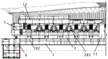
图1是本发明交通枢纽综合体人员疏散设施纵剖面示意图;Fig. 1 is a schematic diagram of a longitudinal section of a personnel evacuation facility in a transportation hub complex of the present invention;
图2是本发明交通枢纽综合体人员疏散设施横断面示意图;Fig. 2 is the cross-sectional schematic diagram of the personnel evacuation facility of the transportation hub complex of the present invention;
图3是本发明地下一层平面示意图;3 is a schematic plan view of the ground floor of the present invention;
图4是本发明出站层平面示意图;4 is a schematic plan view of the outbound layer of the present invention;
图5是本发明快速出站夹层平面示意图。FIG. 5 is a schematic plan view of the fast outbound mezzanine of the present invention.
具体实施方式Detailed ways
下面结合具体实施例以及附图1-5对本发明做进一步说明。The present invention will be further described below with reference to specific embodiments and accompanying drawings 1-5.
如图1-2所示,本发明的一种交通枢纽综合体人员疏散设施,包括交通枢纽结构以及其上的综合开发结构,交通枢纽结构包括多层,由下至上分别为地下一层1、出站层2以及站台层3。如图3所示,交通枢纽结构周边设置有下沉式广场4,下沉式广场4周边设置有可供消防车通行的环形疏散通道5。环形疏散通道5宽度不小于4m,坡度不大于8%,其通过车辆出入口坡道与出站层2的消防车道连通。下沉式广场4顶部开洞,并设置有顶部连桥。除车辆出入口坡道外,所述下沉式广场4顶部开洞比例不小于环形疏散通道5总长度的50%,且开洞均匀设置,开洞位置的间距不大于60m。下沉式广场4顶部开敞,并设置有顶部连桥。下沉式广场4内的地下一层1内设置有车库6、商业设施7以及地铁站厅8。车库6、商业设施7以及地铁站厅8之间均设置有避难走道9。避难走道9两端直通上述环形疏散通道5或下沉式广场4。地下一层1的商业设施 7的出口可分别通向不同的避难走道9或下沉式广场4,同时,地铁站厅8还分别与下沉式广场4、避难走道9疏散连通,且地铁站厅8可通过疏散楼梯间与出站层2的城市通廊10疏散连通。本实施例中,如图3所示,地下一层1内的地铁站厅8两侧对称设置有4组车库6和4组商业设施7,商业设施7与地铁站厅 8之间设置有E形和反E形的避难走道9,商业设施7与车库6之间设置有L形或反L形的避难走道9。地下一层1内共设置有6条相互独立的避难走道9,作为人员疏散的安全区。As shown in Figures 1-2, a transportation hub complex personnel evacuation facility of the present invention includes a transportation hub structure and a comprehensive development structure above it.
如图1-2以及图4所示,出站层2设置有十字交叉设置的城市通廊10以及开敞空间体11,出站层2还设置有被城市通廊10以及开敞空间体11分隔的出站厅12、车库6、出租/长途车候车厅13。出站厅12与该层车库6、出租/长途车候车厅13之间设置有背廊14,背廊14两端敞开通向室外和开敞空间体11。开敞空间体11与站台层3上的高架层候车厅15之间通过扶梯16连接。背廊14 与车库6之间通过防火墙17分隔,与出租/长途车候车厅13之间采用耐火极限不低于2.0h的防火玻璃18分隔,与出站厅12连通位置设置有耐火极限不低于 2.0h的防火玻璃门。开敞空间体11与出租/长途车候车厅13、该层车库6之间采取耐火极限不低于2.0h的防火玻璃18分隔。出站层的车库6按高层汽车库划分防火分区,人员可水平向室外疏散或向开敞空间体11疏散,满足双向疏散条件。出租/长途车候车厅13人员可水平向室外疏散或向开敞空间体11疏散。扶梯16所在的洞口采取耐火极限不低于3.0h的防火隔墙、防火卷帘或防火门进行防火分隔。As shown in Figures 1-2 and 4, the
此外,地下一层1、出站层2之间还设置有地下一层夹层102。地下一层夹层102为车库夹层,按地下汽车库划分防火分区,人员可通过疏散楼梯间向下沉式广场4疏散,满足双向疏散条件要求。In addition, an underground
同时,如图5所示,出站层2以及站台层3之间还设置有快速出站夹层203。快速出站夹层203内设置有快速出站厅2031,快速出站厅2031与出站厅12以及城市通廊10连接为一体,仅作为候车和集散功能,其与商业设施7采用防火墙17分隔,连通部位设置有双道防火卷帘。快速出站厅2031两端分别设置通向室外平台19和开敞空间体回廊20的安全出口,快速出站厅2031通过敞开楼梯与出站厅12连通,用于疏散。快速出站夹层203内的汽车库6按高层汽车库划分防火分区,人员可向开敞空间体回廊20疏散,或通过疏散楼梯间向地面进行疏散,满足双向疏散条件。快速出站夹层203内的商业设施7按规范划分防火分区,人员利用室外平台19、开敞空间体回廊20疏散,或通过疏散楼梯间向背廊14疏散。Meanwhile, as shown in FIG. 5 , a fast
本实施例中,站台层3的轨行区与开敞空间体11之间采用耐火完整性不低于1.0h的固定防火构件分隔,站台层3的每个站台均设置4部楼梯通向出站区域,站台层3人员可向出站层2及快速出站夹层203疏散,不反向疏散到站台层3上部的高架层候车厅15。In this embodiment, the track area of the
上述实施例只是为了更清楚说明本发明的技术方案做出的列举,并非对本发明的限定,本领域的普通技术人员根据本领域的公知常识对本申请技术方案的变通亦均在本申请保护范围之内,总之,上述实施例仅为列举,本申请的保护范围以所附权利要求书范围为准。The above-mentioned embodiments are only enumerations made to illustrate the technical solutions of the present invention more clearly, and are not intended to limit the present invention. The modifications of the technical solutions of the present application by those of ordinary skill in the art according to common knowledge in the field are also within the protection scope of the present application. In short, the above-mentioned embodiments are merely examples, and the protection scope of the present application is subject to the scope of the appended claims.
Claims (10)
Priority Applications (1)
| Application Number | Priority Date | Filing Date | Title |
|---|---|---|---|
| CN202010842883.6A CN112096131B (en) | 2020-08-20 | 2020-08-20 | Transportation hub complex personnel evacuation facility |
Applications Claiming Priority (1)
| Application Number | Priority Date | Filing Date | Title |
|---|---|---|---|
| CN202010842883.6A CN112096131B (en) | 2020-08-20 | 2020-08-20 | Transportation hub complex personnel evacuation facility |
Publications (2)
| Publication Number | Publication Date |
|---|---|
| CN112096131A true CN112096131A (en) | 2020-12-18 |
| CN112096131B CN112096131B (en) | 2022-03-25 |
Family
ID=73754026
Family Applications (1)
| Application Number | Title | Priority Date | Filing Date |
|---|---|---|---|
| CN202010842883.6A Active CN112096131B (en) | 2020-08-20 | 2020-08-20 | Transportation hub complex personnel evacuation facility |
Country Status (1)
| Country | Link |
|---|---|
| CN (1) | CN112096131B (en) |
Cited By (4)
| Publication number | Priority date | Publication date | Assignee | Title |
|---|---|---|---|---|
| CN112922437A (en) * | 2021-01-28 | 2021-06-08 | 杭州中联筑境建筑设计有限公司 | Portable medium-sized railway passenger station arrangement structure |
| CN113802917A (en) * | 2021-09-27 | 2021-12-17 | 杭州中联筑境建筑设计有限公司 | Three-dimensional composite building structure in front of railway passenger station |
| CN116738524A (en) * | 2023-01-05 | 2023-09-12 | 天津泰达消防科技有限公司 | Calculation method for the width of commercial street evacuation walkways |
| CN117272485A (en) * | 2023-10-17 | 2023-12-22 | 建研防火科技有限公司 | A numerical simulation method for ultra-long cross-channel spacing and parking locations based on fire smoke stratification |
Citations (4)
| Publication number | Priority date | Publication date | Assignee | Title |
|---|---|---|---|---|
| CN108252331A (en) * | 2018-04-12 | 2018-07-06 | 北京市市政工程设计研究总院有限公司 | A kind of subway concourse Open Type Underground Station |
| CN110700318A (en) * | 2019-11-19 | 2020-01-17 | 北京市市政工程设计研究总院有限公司 | An Intercity Railway Underground Station Integrated Development Above the Track Area |
| CN210828495U (en) * | 2019-07-15 | 2020-06-23 | 中铁二院工程集团有限责任公司 | Arrangement structure of non-column subway station in public area |
| CN211173275U (en) * | 2019-09-26 | 2020-08-04 | 湖北工业大学 | Line-side down-type small and medium-sized high-speed railway station building layout structure |
-
2020
- 2020-08-20 CN CN202010842883.6A patent/CN112096131B/en active Active
Patent Citations (4)
| Publication number | Priority date | Publication date | Assignee | Title |
|---|---|---|---|---|
| CN108252331A (en) * | 2018-04-12 | 2018-07-06 | 北京市市政工程设计研究总院有限公司 | A kind of subway concourse Open Type Underground Station |
| CN210828495U (en) * | 2019-07-15 | 2020-06-23 | 中铁二院工程集团有限责任公司 | Arrangement structure of non-column subway station in public area |
| CN211173275U (en) * | 2019-09-26 | 2020-08-04 | 湖北工业大学 | Line-side down-type small and medium-sized high-speed railway station building layout structure |
| CN110700318A (en) * | 2019-11-19 | 2020-01-17 | 北京市市政工程设计研究总院有限公司 | An Intercity Railway Underground Station Integrated Development Above the Track Area |
Non-Patent Citations (3)
| Title |
|---|
| MANSHUAI51555: "郑州东站媒体介绍", 《HTTPS://WENKU.BAIDU.COM/VIEW/CBC631DFCE2F0066F53322CE.HTML》 * |
| 中华人民共和国公安部主编: "《建筑设计防火规范 GB50016-2014(2018版)》", 31 May 2018 * |
| 卫文彬等: "地铁站厅共享空间商业防火及疏散", 《消防科学与技术》 * |
Cited By (6)
| Publication number | Priority date | Publication date | Assignee | Title |
|---|---|---|---|---|
| CN112922437A (en) * | 2021-01-28 | 2021-06-08 | 杭州中联筑境建筑设计有限公司 | Portable medium-sized railway passenger station arrangement structure |
| CN113802917A (en) * | 2021-09-27 | 2021-12-17 | 杭州中联筑境建筑设计有限公司 | Three-dimensional composite building structure in front of railway passenger station |
| CN113802917B (en) * | 2021-09-27 | 2023-03-10 | 杭州中联筑境建筑设计有限公司 | Three-dimensional composite building structure in front of railway passenger station |
| CN116738524A (en) * | 2023-01-05 | 2023-09-12 | 天津泰达消防科技有限公司 | Calculation method for the width of commercial street evacuation walkways |
| CN116738524B (en) * | 2023-01-05 | 2026-07-28 | 天津泰达消防科技有限公司 | Method for calculating width of commercial street refuge walkway |
| CN117272485A (en) * | 2023-10-17 | 2023-12-22 | 建研防火科技有限公司 | A numerical simulation method for ultra-long cross-channel spacing and parking locations based on fire smoke stratification |
Also Published As
| Publication number | Publication date |
|---|---|
| CN112096131B (en) | 2022-03-25 |
Similar Documents
| Publication | Publication Date | Title |
|---|---|---|
| CN112096131B (en) | Transportation hub complex personnel evacuation facility | |
| CN204055768U (en) | A kind of subway station | |
| CN111086532A (en) | Super subway system and operation mode thereof | |
| CN110700318A (en) | An Intercity Railway Underground Station Integrated Development Above the Track Area | |
| CN104727603B (en) | Self-driving type non-mechanical three-dimensional parking system | |
| CN106274913A (en) | A kind of track traffic station platform planar structure system | |
| CN211395746U (en) | Intercity railway underground station of track area top integration development | |
| CN103264702A (en) | Constructing method of air rail transit transportation system network | |
| CN205474885U (en) | Single track station of way midspan seat formula | |
| CN211173275U (en) | Line-side down-type small and medium-sized high-speed railway station building layout structure | |
| CN206841421U (en) | The urban track traffic transfer stop of separate type subway concourse | |
| CN215562792U (en) | Underground station with inverted station hall layer | |
| CN112252776B (en) | An interchange station system with corridors suitable for suspended rail transit | |
| CN115075619A (en) | High-rise residential building | |
| CN113026812B (en) | Subway station capable of being built together with property development | |
| CN219365567U (en) | Epidemic combined special flight near-far machine position terminal building structure | |
| CN218024846U (en) | Off-building elevator system suitable for old building transformation | |
| CN216007960U (en) | Canopy upper cover building structure for high-speed railway platform | |
| CN110626359A (en) | Layout structure of a side-type station public area on the first basement level | |
| CN218228978U (en) | Double-layer atrium subway station with station city integrated | |
| CN205035706U (en) | Three -dimensional stack transportation junction of festival ground type | |
| CN212292418U (en) | Accessible structure of registering one's residence of elevator is add to existing house | |
| CN113863771A (en) | Canopy upper cover building structure for high-speed railway platform | |
| CN105755917B (en) | Two layers of people's car mutual of one kind and separation Public Transport Junction system | |
| CN106945673A (en) | A kind of subway or light rail station an island platform flat shape method for designing |
Legal Events
| Date | Code | Title | Description |
|---|---|---|---|
| PB01 | Publication | ||
| PB01 | Publication | ||
| SE01 | Entry into force of request for substantive examination | ||
| SE01 | Entry into force of request for substantive examination | ||
| GR01 | Patent grant | ||
| GR01 | Patent grant |