CN112093349A - Jacking linkage type sixteen-wheel four-way shuttle - Google Patents
Jacking linkage type sixteen-wheel four-way shuttle Download PDFInfo
- Publication number
- CN112093349A CN112093349A CN202010968454.3A CN202010968454A CN112093349A CN 112093349 A CN112093349 A CN 112093349A CN 202010968454 A CN202010968454 A CN 202010968454A CN 112093349 A CN112093349 A CN 112093349A
- Authority
- CN
- China
- Prior art keywords
- jacking
- wheel
- longitudinal
- shaft
- transverse
- Prior art date
- Legal status (The legal status is an assumption and is not a legal conclusion. Google has not performed a legal analysis and makes no representation as to the accuracy of the status listed.)
- Granted
Links
Images


Classifications
-
- B—PERFORMING OPERATIONS; TRANSPORTING
- B65—CONVEYING; PACKING; STORING; HANDLING THIN OR FILAMENTARY MATERIAL
- B65G—TRANSPORT OR STORAGE DEVICES, e.g. CONVEYORS FOR LOADING OR TIPPING, SHOP CONVEYOR SYSTEMS OR PNEUMATIC TUBE CONVEYORS
- B65G1/00—Storing articles, individually or in orderly arrangement, in warehouses or magazines
- B65G1/02—Storage devices
- B65G1/04—Storage devices mechanical
- B65G1/0492—Storage devices mechanical with cars adapted to travel in storage aisles
-
- B—PERFORMING OPERATIONS; TRANSPORTING
- B66—HOISTING; LIFTING; HAULING
- B66F—HOISTING, LIFTING, HAULING OR PUSHING, NOT OTHERWISE PROVIDED FOR, e.g. DEVICES WHICH APPLY A LIFTING OR PUSHING FORCE DIRECTLY TO THE SURFACE OF A LOAD
- B66F9/00—Devices for lifting or lowering bulky or heavy goods for loading or unloading purposes
- B66F9/06—Devices for lifting or lowering bulky or heavy goods for loading or unloading purposes movable, with their loads, on wheels or the like, e.g. fork-lift trucks
- B66F9/065—Devices for lifting or lowering bulky or heavy goods for loading or unloading purposes movable, with their loads, on wheels or the like, e.g. fork-lift trucks non-masted
-
- B—PERFORMING OPERATIONS; TRANSPORTING
- B66—HOISTING; LIFTING; HAULING
- B66F—HOISTING, LIFTING, HAULING OR PUSHING, NOT OTHERWISE PROVIDED FOR, e.g. DEVICES WHICH APPLY A LIFTING OR PUSHING FORCE DIRECTLY TO THE SURFACE OF A LOAD
- B66F9/00—Devices for lifting or lowering bulky or heavy goods for loading or unloading purposes
- B66F9/06—Devices for lifting or lowering bulky or heavy goods for loading or unloading purposes movable, with their loads, on wheels or the like, e.g. fork-lift trucks
- B66F9/075—Constructional features or details
- B66F9/07586—Suspension or mounting of wheels on chassis
-
- B—PERFORMING OPERATIONS; TRANSPORTING
- B60—VEHICLES IN GENERAL
- B60G—VEHICLE SUSPENSION ARRANGEMENTS
- B60G17/00—Resilient suspensions having means for adjusting the spring or vibration-damper characteristics, for regulating the distance between a supporting surface and a sprung part of vehicle or for locking suspension during use to meet varying vehicular or surface conditions, e.g. due to speed or load
- B60G17/015—Resilient suspensions having means for adjusting the spring or vibration-damper characteristics, for regulating the distance between a supporting surface and a sprung part of vehicle or for locking suspension during use to meet varying vehicular or surface conditions, e.g. due to speed or load the regulating means comprising electric or electronic elements
- B60G17/0152—Resilient suspensions having means for adjusting the spring or vibration-damper characteristics, for regulating the distance between a supporting surface and a sprung part of vehicle or for locking suspension during use to meet varying vehicular or surface conditions, e.g. due to speed or load the regulating means comprising electric or electronic elements characterised by the action on a particular type of suspension unit
-
- B—PERFORMING OPERATIONS; TRANSPORTING
- B60—VEHICLES IN GENERAL
- B60G—VEHICLE SUSPENSION ARRANGEMENTS
- B60G2300/00—Indexing codes relating to the type of vehicle
- B60G2300/26—Carts
-
- B—PERFORMING OPERATIONS; TRANSPORTING
- B60—VEHICLES IN GENERAL
- B60G—VEHICLE SUSPENSION ARRANGEMENTS
- B60G2500/00—Indexing codes relating to the regulated action or device
- B60G2500/30—Height or ground clearance
Landscapes
- Engineering & Computer Science (AREA)
- Transportation (AREA)
- Structural Engineering (AREA)
- Mechanical Engineering (AREA)
- Civil Engineering (AREA)
- Life Sciences & Earth Sciences (AREA)
- Geology (AREA)
- Handcart (AREA)
- Platform Screen Doors And Railroad Systems (AREA)
- Warehouses Or Storage Devices (AREA)
- Bridges Or Land Bridges (AREA)
Abstract
本发明公开了一种顶升联动式十六轮四向穿梭车,包括支撑框架、横向行走驱动机构、纵向行走驱动机构和斜拉换向及顶升机构;横向行走驱动机构包括横向主动轮、第一横向从动轮、第二横向从动轮和第三横向从动轮;纵向行走驱动机构包括第一纵向主动轮、第二纵向主动轮、第一纵向从动轮和第一纵向从动轮;以及换向及顶升机构包括顶升横板、第一斜拉顶升滑块和第二斜拉顶升滑块,顶升轴孔内活动设置有滚珠轴套,滚珠轴套的前后两侧设置有斜拉顶升柱,两端的斜拉顶升滑块之间通过顶升轴连接。本发明的顶升联动式十六轮四向穿梭车,采用16轮双向行走小车的结构设计,大大提高小车的载重能力和过坎能力;且其结构设计紧凑,既降低成本,又节省空间。
The invention discloses a jacking linkage type sixteen-wheel four-direction shuttle vehicle, which comprises a support frame, a lateral travel drive mechanism, a longitudinal travel drive mechanism, and an oblique pull reversing and jacking mechanism; the lateral travel drive mechanism includes a lateral driving wheel, a first transverse driven wheel, a second transverse driven wheel and a third transverse driven wheel; the longitudinal travel drive mechanism includes a first longitudinal driving wheel, a second longitudinal driving wheel, a first longitudinal driven wheel and a first longitudinal driven wheel; and a reversing And the jacking mechanism includes a jacking horizontal plate, a first inclined-pulling jacking block and a second inclined-pulling jacking block, a ball bushing is movably arranged in the jacking shaft hole, and the front and rear sides of the ball bushing are provided with inclined pulleys. Pull the jacking column, and the inclined-pull jacking sliders at both ends are connected by the jacking shaft. The jacking linkage type sixteen-wheel four-way shuttle of the present invention adopts the structural design of a 16-wheel two-way traveling trolley, which greatly improves the load capacity and the sill-crossing ability of the trolley; and the compact structure design not only reduces costs, but also saves space.
Description
技术领域technical field
本发明涉及一种四向穿梭车,尤其涉及一种顶升联动式十六轮四向穿梭车。The invention relates to a four-way shuttle, in particular to a jacking linkage type sixteen-wheel four-way shuttle.
背景技术Background technique
随着仓储物流业的快速发展,对立体仓库空间的利用率提出了越来越高的要求,希望立体仓库平面上布置更多的货架,高度方向上布置更多的货架隔层,最大限度减少进货、卸货通道占据的空间。With the rapid development of warehousing and logistics industry, higher and higher requirements are put forward for the utilization rate of three-dimensional warehouse space. The space occupied by the incoming and outgoing aisles.
目前的立体库结构更多采用一条进货卸货巷道与多条与其垂直相连存货架巷道的模式,这就要求穿梭车必须可以纵向、横向两个互相垂直的方向行走。现有技术中,立体仓库通常使用子母车系统,即母车承载着子车在进货、卸货巷道行走,然后子车从与母车行走方向相垂直的方向驶出,进入货架巷道,之后再原路回到母车上,最后再由母车带走。The current three-dimensional warehouse structure more adopts the mode of one loading and unloading lane and multiple storage rack lanes vertically connected to it, which requires that the shuttle car must be able to travel in two mutually perpendicular directions, vertical and horizontal. In the prior art, the three-dimensional warehouse usually uses a sub-mother car system, that is, the main car carries the sub-cars and walks in the incoming and unloading aisles, and then the sub-cars drive out in a direction perpendicular to the direction of the mother car, enter the racking aisle, and then Back on the original road to the mother car, and finally taken away by the mother car.
现有子母车两台穿梭车组合的方式,大多采用双向8轮结构设计,其货物承载量低、过坎能力弱,且故障率高,已不能满足日益繁忙的仓储物流需要;且其一般采用凸轮顶升结构,存在凸轮易磨损,从动件受力不均匀及传动效率低的缺陷;此外,现有的子母车穿梭车,不仅自身占据了相当大的空间,减少货架及隔层的数量,降低了立体库的空间利用率,还增加了制造、采购及维护成本。The existing combination of two shuttles of the sub-mother car mostly adopts a two-way 8-wheel structure design, which has low cargo carrying capacity, weak ability to pass sills, and high failure rate, which can no longer meet the increasingly busy warehousing and logistics needs; and its general The cam jacking structure has the defects of easy wear of the cam, uneven force on the follower and low transmission efficiency; in addition, the existing shuttle car not only occupies a considerable space by itself, but also reduces the number of shelves and partitions. It reduces the space utilization of the three-dimensional library and increases the manufacturing, procurement and maintenance costs.
发明内容SUMMARY OF THE INVENTION
本发明所要解决的技术问题是:针对现有技术中的上述缺陷,提出一种顶升联动式十六轮四向穿梭车。The technical problem to be solved by the present invention is: aiming at the above-mentioned defects in the prior art, a jacking linkage type sixteen-wheel four-way shuttle is proposed.
为实现上述目的,本发明采用以下技术方案:To achieve the above object, the present invention adopts the following technical solutions:
本发明提供一种顶升联动式十六轮四向穿梭车,包括支撑框架和装设于所述支撑框架上的横向行走驱动机构、纵向行走驱动机构和斜拉换向及顶升机构,其中:The present invention provides a jacking linkage type sixteen-wheel four-way shuttle, comprising a support frame, a lateral travel drive mechanism, a longitudinal travel drive mechanism, and an oblique pull reversing and jacking mechanism installed on the support frame, wherein:
所述横向行走驱动机构包括分别对称布置于所述支撑框架前后两侧的横向主动轮、第一横向从动轮、第二横向从动轮和第三横向从动轮,两所述横向主动轮分别设置于横向传动轴两端,两所述第三横向从动轮分别设置于横向连接轴两端,且所述横向传动轴通过第一横向传动带传动连接横向电机;The lateral walking drive mechanism includes a lateral driving wheel, a first lateral driven wheel, a second lateral driven wheel and a third lateral driven wheel, which are symmetrically arranged on the front and rear sides of the support frame, respectively. the two ends of the transverse transmission shaft, the two third transverse driven wheels are respectively arranged at both ends of the transverse connection shaft, and the transverse transmission shaft is connected to the transverse motor through the first transverse transmission belt;
所述纵向行走驱动机构包括分别对称布置于所述支撑框架左右两侧的第一纵向主动轮、第二纵向主动轮、第一纵向从动轮和第一纵向从动轮,两侧的所述第一纵向主动轮和第二纵向主动轮分别通过第一纵向传动带连接纵向传动轴,且所述纵向传动轴通过第二纵向传动带传动连接纵向电机;以及The longitudinal travel drive mechanism includes a first longitudinal driving wheel, a second longitudinal driving wheel, a first longitudinal driven wheel and a first longitudinal driven wheel symmetrically arranged on the left and right sides of the supporting frame, and the first longitudinal driving wheel on both sides. The longitudinal driving wheel and the second longitudinal driving wheel are respectively connected to the longitudinal transmission shaft through the first longitudinal transmission belt, and the longitudinal transmission shaft is drivingly connected to the longitudinal motor through the second longitudinal transmission belt; and
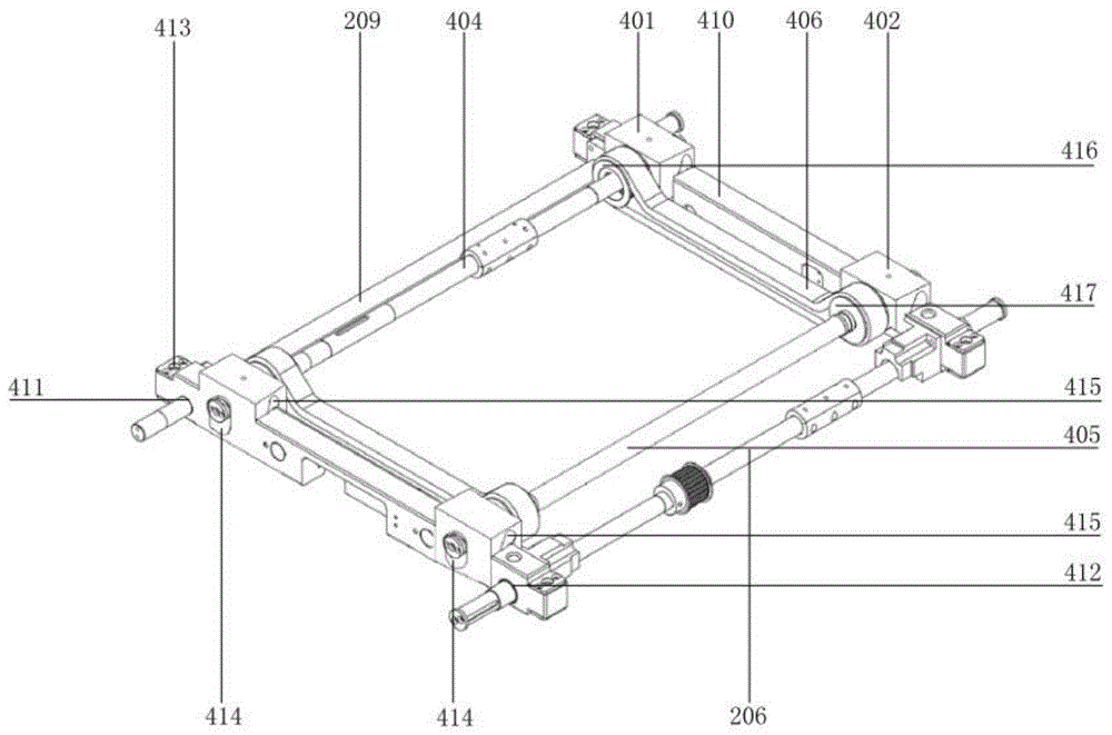
所述斜拉换向及顶升机构包括分别对称布置于所述支撑框架前后两侧的顶升横板、分别设置于所述顶升横板两端的第一斜拉顶升滑块和第二斜拉顶升滑块;所述顶升横板两端分别开设有用于装配所述横向传动轴和横向连接轴的第一换向装配槽和第二换向装配槽;所述第一斜拉顶升滑块和第二斜拉顶升滑块的结构相同,其上开设有左右贯通的顶升轴孔和前后贯通且呈倾斜布置的顶升斜孔;所述顶升轴孔内活动设置有滚珠轴套,所述滚珠轴套的前后两侧设置有斜拉顶升柱,且所述斜拉顶升柱活动嵌设于所述顶升斜孔内;两所述第一斜拉顶升滑块之间通过活动穿设于滚珠轴套内的第一顶升轴连接,两所述第二斜拉顶升轴之间通过活动穿设于滚珠轴套内的第二顶升轴连接,且所述第一顶升轴和/或第二顶升轴通过顶升传动带传动连接顶升电机。The inclined pull reversing and jacking mechanism includes jacking cross plates symmetrically arranged on the front and rear sides of the support frame, a first inclined pulling jacking block and a second jacking block respectively arranged at both ends of the jacking cross plate. The inclined pull jacking block; the two ends of the jacking transverse plate are respectively provided with a first reversing assembly groove and a second reversing assembly groove for assembling the transverse transmission shaft and the transverse connecting shaft; the first inclined pull The jacking block and the second inclined-pull jacking block have the same structure, and are provided with a jacking shaft hole that penetrates left and right and a jacking inclined hole that penetrates through the front and rear and is arranged obliquely; the jacking shaft hole is movably arranged There are ball bushings, and the front and rear sides of the ball bushings are provided with inclined-pulling jacking columns, and the inclined-pulling jacking columns are movably embedded in the lifting inclined holes; the two first inclined-pulling tops The lifting blocks are connected by a first lifting shaft movably penetrated in the ball bushing, and the two second inclined-pulling lifting shafts are connected by a second lifting shaft movably penetrated in the ball bushing , and the first jacking shaft and/or the second jacking shaft are connected to the jacking motor through a jacking transmission belt.
进一步地,在所述的顶升联动式十六轮四向穿梭车上,所述支撑框架的前后两侧壁分别开设四个方形装配孔,所述支撑框架的左右两侧壁分别开设四个圆形装配孔,其中:Further, on the described jack-up linkage type sixteen-wheel four-way shuttle, the front and rear side walls of the support frame are respectively provided with four square assembly holes, and the left and right side walls of the support frame are respectively provided with four square mounting holes. Circular mounting holes where:
所述横向主动轮与穿过所述第二换向装配槽、对应所述方形装配孔的所述横向传动轴连接,所述第一横向从动轮和第二横向从动轮的轮轴分别穿过对应的所述方形装配孔连接所述顶升梁,所述第三横向从动轮与穿过所述第一换向装配槽、对应所述方形装配孔的横向连接轴连接;The transverse driving wheel is connected with the transverse transmission shaft passing through the second reversing assembly groove and corresponding to the square assembly hole, and the axles of the first transverse driven wheel and the second transverse driven wheel pass through the corresponding The square assembly hole is connected to the jacking beam, and the third lateral driven wheel is connected to the lateral connection shaft passing through the first reversing assembly groove and corresponding to the square assembly hole;
所述第一纵向主动轮和第二纵向主动轮的轮轴分别穿过所述圆形装配孔通过第一轴承座连接所述支撑框架底部,所述第一纵向从动轮、第一纵向从动轮设置于对应的所述圆形装配孔内。The axles of the first longitudinal driving wheel and the second longitudinal driving wheel respectively pass through the circular assembly hole and connect to the bottom of the support frame through a first bearing seat, and the first longitudinal driven wheel and the first longitudinal driven wheel are arranged in the corresponding circular mounting holes.
进一步地,在所述的顶升联动式十六轮四向穿梭车上,所述横向主动轮通过第二横向传动带连接同侧的所述第一横向从动轮;和/或通过第二横向传动带连接同侧的所述第三横向从动轮。Further, on the described jacking linkage type sixteen-wheel four-way shuttle, the transverse driving wheel is connected to the first transverse driven wheel on the same side through a second transverse transmission belt; and/or through a second transverse transmission belt Connect the third lateral driven wheel on the same side.
进一步地,在所述的顶升联动式十六轮四向穿梭车上,还包括设置于所述第一纵向传动带外侧的张紧调节机构,其中:Further, on the described jacking linkage type sixteen-wheel four-way shuttle vehicle, it also includes a tension adjusting mechanism arranged on the outer side of the first longitudinal transmission belt, wherein:
所述张紧调节机构包括贴合于所述第一纵向传动带外侧布置的第一张紧轮和第二张紧轮,所述第一张紧轮通过第一固定板固定设置于所述支撑框架内侧壁,所述第二张紧轮通过调节板活动设置于所述支撑框架内侧壁。The tensioning adjustment mechanism includes a first tensioning wheel and a second tensioning wheel that are attached to the outside of the first longitudinal transmission belt, and the first tensioning wheel is fixedly arranged on the support frame through a first fixing plate The inner side wall, the second tensioning wheel is movably arranged on the inner side wall of the support frame through the adjusting plate.
进一步优选地,在所述的顶升联动式十六轮四向穿梭车上,所述调节板上水平开设调节方孔,并通过穿设于所述调节方孔内的螺栓活动固定于所述支撑框架内侧壁,且其一端通过调节螺母及螺栓与固定于所述支撑框架内侧壁的第二固定板可调节连接。Further preferably, on the lifting linkage type sixteen-wheel four-way shuttle, the adjusting plate is provided with an adjusting square hole horizontally, and is movably fixed to the The inner side wall of the support frame is adjustable and connected to the second fixing plate fixed to the inner side wall of the support frame through adjusting nuts and bolts at one end.
进一步地,在所述的顶升联动式十六轮四向穿梭车上,所述斜拉换向及顶升机构还包括:Further, on the described jacking linkage type sixteen-wheel four-way shuttle, the cable pull reversing and jacking mechanism further includes:
第二轴承座,其设置于所述支撑框架上,其顶端设置有轴承,以支撑所述第一顶升轴和/或第二顶升轴;a second bearing seat, which is arranged on the support frame, and a bearing is arranged at the top end to support the first jacking shaft and/or the second jacking shaft;
顶升螺母,其固定套设于所述滚珠轴套上,且其前后两侧壁分别与所述斜拉顶升柱焊接连接。The jacking nut is fixedly sleeved on the ball bearing sleeve, and the front and rear side walls of the jacking nut are respectively welded and connected with the inclined-pulling jacking column.
进一步地,在所述的顶升联动式十六轮四向穿梭车上,所述顶升横板通过其两端开设的导向滑槽上下滑动连接所述支撑框架四角位置的顶升导柱,所述顶升导柱的上下两端分别通过导柱固定板固定连接所述支撑框架。Further, on the lifting linkage type sixteen-wheel four-way shuttle, the lifting cross plate is connected to the lifting guide posts at the four corners of the supporting frame through the guide chutes opened at both ends of the lifting cross plate. The upper and lower ends of the lifting guide column are respectively fixedly connected to the support frame through the guide column fixing plate.
进一步地,在所述的顶升联动式十六轮四向穿梭车上,所述顶升斜孔的倾斜角度为5-85°,且其垂直高度等于所述顶升轴孔的垂直高度。Further, on the lifting linkage type sixteen-wheel four-way shuttle, the inclination angle of the lifting inclined hole is 5-85°, and the vertical height thereof is equal to the vertical height of the lifting shaft hole.
进一步地,在所述的顶升联动式十六轮四向穿梭车上,所述第一顶升轴的两端设置第一同步轮,所述第二顶升轴设置第二同步轮,所述第一同步轮和第二同步轮之间通过顶升同步带连接。Further, on the jacking linkage type sixteen-wheel four-way shuttle, both ends of the first jacking shaft are provided with first synchronizing wheels, and the second jacking shaft is provided with second synchronizing wheels, so The first synchronous wheel and the second synchronous wheel are connected by a jacking synchronous belt.
进一步地,在所述的顶升联动式十六轮四向穿梭车上,所述顶升同步带的两端靠近所述第一同步轮和第二同步轮的位置分别设置顶升张紧轮。Further, on the lifting linkage type sixteen-wheel four-way shuttle, the two ends of the lifting synchronous belt are respectively provided with lifting tensioning pulleys at the positions close to the first synchronizing wheel and the second synchronizing wheel. .
本发明采用上述技术方案,与现有技术相比,具有如下技术效果:The present invention adopts the above-mentioned technical scheme, compared with the prior art, has the following technical effects:
(1)两第一斜拉顶升滑块通过第一顶升轴横向布置,两第二斜拉顶升滑块之间通过第二顶升轴横向布置,且第一顶升轴和第二顶升轴之间采用顶升同步带实现同步联动,提高了第一斜拉顶升滑块与第二斜拉顶升滑块升降的一致性,保证了小车运行稳定性;(1) The two first inclined-pulled jacking blocks are arranged laterally through the first jacking shaft, and the two second inclined-pulling jacking blocks are laterally arranged through the second jacking shaft, and the first jacking shaft and the second jacking block are horizontally arranged. The jacking synchronous belt is used between the jacking shafts to realize synchronous linkage, which improves the consistency of the lifting of the first inclined-pull jacking block and the second inclined-pull jacking block, and ensures the running stability of the trolley;
(2)采用横向8轮纵向8轮及强化的支撑框架,提高了载重能力;并优化了各车轮的安装位置,使小车具有较好的过坎能力;(2) The use of 8 horizontal wheels and 8 vertical wheels and a reinforced support frame improves the load capacity; and optimizes the installation position of each wheel, so that the trolley has a better ability to pass sills;
(3)为匹配16轮,优化了车轮传动机构,通过将纵向传动轴的位置上移,及加大纵向车轮的直径,使小车具有较好的承载能力;(3) In order to match 16 wheels, the wheel transmission mechanism is optimized. By moving the position of the longitudinal transmission shaft upwards and increasing the diameter of the longitudinal wheels, the trolley has a better bearing capacity;
(4)采用张紧调节机构调整第一纵向传动带的张紧度,同时保证第一纵向主动轮和第二纵向主动轮动力传输的稳定性和连续性;(4) The tension adjustment mechanism is used to adjust the tension of the first longitudinal drive belt, while ensuring the stability and continuity of the power transmission of the first longitudinal driving wheel and the second longitudinal driving wheel;
(5)斜拉换向及顶升机构采用斜拉顶升滑块与斜拉顶升柱滚动线接触,传动效率高,压力角无变化,顶升滑块两侧的顶升斜孔对称布置,受力均匀;其设计新颖,结构紧凑,运行稳定,体积小,载重大,减少了机械机构的维护、保养次数,工作效率高,使用寿命长;(5) The inclined-pulling reversing and jacking mechanism adopts the inclined-pulling jacking block to contact the rolling line of the inclined-pulling jacking column, with high transmission efficiency and no change in the pressure angle. The jacking inclined holes on both sides of the jacking block are symmetrically arranged , the force is uniform; its novel design, compact structure, stable operation, small size, heavy load, reducing the maintenance and maintenance times of the mechanical mechanism, high work efficiency and long service life;
(6)采用滚柱丝杆与滚珠轴套相配合的传动结构,传动效率达50%-70%,且滚珠轴套与顶升轴之间通过顶升螺母直接配合连接,减少了动能损失;(6) The transmission structure of the roller screw and the ball bushing is adopted, and the transmission efficiency is 50%-70%, and the ball bushing and the jacking shaft are directly connected by the jacking nut, which reduces the kinetic energy loss;
(7)该十六轮四向穿梭车,结构设计紧凑,既降低成本,又节省空间;且减小了小车整体重量和体积,提升运行能力和货物存取效率。(7) The sixteen-wheel four-way shuttle has a compact structure design, which not only reduces costs, but also saves space; it also reduces the overall weight and volume of the trolley, and improves operating capacity and cargo storage efficiency.
附图说明Description of drawings
图1为本发明一种顶升联动式十六轮四向穿梭车的俯视结构示意图;Fig. 1 is a top-view structural schematic diagram of a jack-up linkage type sixteen-wheel four-way shuttle according to the present invention;
图2为本发明一种顶升联动式十六轮四向穿梭车的主视结构示意图;Figure 2 is a schematic front view of the structure of a jack-up linkage type sixteen-wheel four-way shuttle according to the present invention;
图3为本发明一种顶升联动式十六轮四向穿梭车的侧视结构示意图;Figure 3 is a schematic side view of the structure of a jack-up linkage type sixteen-wheel four-way shuttle according to the present invention;
图4为本发明一种顶升联动式十六轮四向穿梭车的立体结构示意图;Fig. 4 is a three-dimensional structural schematic diagram of a jacking linkage type sixteen-wheel four-way shuttle according to the present invention;
图5为本发明一种顶升联动式十六轮四向穿梭车中支撑框架的结构示意图;5 is a schematic structural diagram of a support frame in a jacking-up linkage type sixteen-wheel four-way shuttle according to the present invention;
图6为本发明一种顶升联动式十六轮四向穿梭车中张紧调节机构的装配结构示意图;6 is a schematic diagram of the assembly structure of a tensioning adjusting mechanism in a jacking linkage type sixteen-wheel four-way shuttle according to the present invention;
图7为本发明一种顶升联动式十六轮四向穿梭车中斜拉换向及顶升机构的部分结构示意图;7 is a partial structural schematic diagram of a cable-pull reversing and jacking mechanism in a jacking linkage type sixteen-wheel four-way shuttle according to the present invention;
图8为本发明一种顶升联动式十六轮四向穿梭车中斜拉换向及顶升机构的整体结构示意图;8 is a schematic diagram of the overall structure of the cable pull reversing and jacking mechanism in a jacking linkage type sixteen-wheel four-way shuttle according to the present invention;
图9为本发明一种顶升联动式十六轮四向穿梭车中斜拉顶升滑块的结构示意图;9 is a schematic structural diagram of an inclined-pull jacking slider in a jacking linkage type sixteen-wheel four-way shuttle according to the present invention;
图10为本发明一种顶升联动式十六轮四向穿梭车中斜拉顶升滑块的剖视结构示意图;10 is a cross-sectional structural schematic diagram of an inclined-pull jacking slider in a jacking linkage type sixteen-wheel four-way shuttle according to the present invention;
图11为本发明一种顶升联动式十六轮四向穿梭车中滚珠丝杆与滚珠轴套的剖视结构示意图;11 is a cross-sectional structural schematic diagram of a ball screw and a ball bush in a jacking-up linkage type sixteen-wheel four-way shuttle according to the present invention;
图12为本发明一种顶升联动式十六轮四向穿梭车中斜拉顶升滑块的结构示意图;12 is a schematic structural diagram of an inclined-pull jacking slider in a jacking linkage type sixteen-wheel four-way shuttle according to the present invention;
其中,各附图标记为:Among them, each reference sign is:
100-支撑框架,101-方形装配孔,102-圆形装配孔,103-顶升导柱,104-导柱固定板,105-第一轴承座;100-supporting frame, 101-square mounting hole, 102-circular mounting hole, 103-lifting guide post, 104-guide post fixing plate, 105-first bearing seat;
200-横向行走驱动机构,201-横向主动轮,202-第一横向从动轮,203-第二横向从动轮,204-第三横向从动轮,205-第二横向传动带,206-横向传动轴,207-第一横向传动带,208-横向电机,209-横向连接轴,210-十字减速器;200-transverse driving mechanism, 201-transverse driving wheel, 202-first transverse driven wheel, 203-second transverse driven wheel, 204-third transverse driven wheel, 205-second transverse transmission belt, 206-transverse transmission shaft, 207-first transverse transmission belt, 208-transverse motor, 209-transverse connecting shaft, 210-cross reducer;
300-纵向行走驱动机构,301-第一纵向主动轮,302-第二纵向主动轮,303-第一纵向从动轮,304-第一纵向从动轮,305-纵向传动轴,306-第二纵向传动带,307-纵向电机,308-第一纵向传动带;300-longitudinal travel drive mechanism, 301-first longitudinal driving wheel, 302-second longitudinal driving wheel, 303-first longitudinal driven wheel, 304-first longitudinal driven wheel, 305-longitudinal transmission shaft, 306-second longitudinal Transmission belt, 307-longitudinal motor, 308-first longitudinal transmission belt;
400-斜拉换向及顶升机构,401-第一斜拉顶升滑块,402-第二斜拉顶升滑块,403-第二轴承座,404-第一顶升轴,405-第二顶升轴,406-顶升同步带,407-顶升张紧轮,408-顶升传动带,409-顶升电机,410-顶升横板,411-第一换向装配槽,412-第二换向装配槽,413-导向滑槽,414-顶升轴孔,415-顶升斜孔,416-第一同步轮,417-第二同步轮,418-滚珠轴套,419-顶升螺母,420-斜拉顶升柱;400-Cable-pull reversing and jacking mechanism, 401-First inclined-pull jacking block, 402-Second inclined-pull jacking block, 403-Second bearing seat, 404-First jacking shaft, 405- Second jacking shaft, 406- jacking timing belt, 407- jacking tensioner, 408- jacking transmission belt, 409- jacking motor, 410- jacking cross plate, 411- first reversing assembly groove, 412 -Second reversing assembly groove, 413-Guide chute, 414-Jumping shaft hole, 415-Jumping inclined hole, 416-First synchronizing wheel, 417-Second synchronizing pulley, 418-Ball bushing, 419- Jacking nut, 420-cable-stayed jacking column;
500-电池组,600-控制器;700-张紧调节机构,701-第一张紧轮,702-第一固定板,703-第二张紧轮,704-调节板,705-调节方孔,706-第二固定板。500-battery pack, 600-controller; 700-tension adjustment mechanism, 701-first tensioner, 702-first fixing plate, 703-second tensioner, 704-adjustment plate, 705-adjustment square hole , 706-Second fixed plate.
具体实施方式Detailed ways
下面通过具体实施例对本发明进行详细和具体的介绍,以使更好的理解本发明,但是下述实施例并不限制本发明范围。The present invention will be described in detail and concretely below through specific embodiments, so as to make the present invention better understood, but the following embodiments do not limit the scope of the present invention.
在一些实施例中,如图1所示,提供一种顶升联动式十六轮四向穿梭车,包括支撑框架100和装设于支撑框架100上的横向行走驱动机构200、纵向行走驱动机构300、斜拉换向及顶升机构400、电池组500和控制器600。In some embodiments, as shown in FIG. 1 , a jacking linkage type sixteen-wheel four-way shuttle is provided, including a
在其中的一个实施例中,支撑框架100是通过钣金折弯及局部加强筋连成的一个整体,极大提高整车的承载能力;电池组500作为动力源给整车提高动力,电池组500可采用锂离子可充电电池、蓄电池或其他任何蓄能电池,为小车各功能电源供电;控制器600作为整车的大脑,控制整车的运动,控制器600电连接电池组500、横向行走驱动机构200的横向电机208、纵向行走驱动机构300、纵向电机307和换向及顶升机构400的顶升电机408,通过控制器600控制小车灵活径向纵向或横向行走,并通过换向及顶升机构400实现小车顶升和换向。In one of the embodiments, the
在一些实施例中,如图2和图4所示,横向行走驱动机构200作为十六轮四向穿梭车横向移动的执行单元,其包括分别对称布置于支撑框架100前后两侧的横向主动轮201、第一横向从动轮202、第二横向从动轮203和第三横向从动轮204,其中,横向主动轮201、第一横向从动轮202、第二横向从动轮203和第三横向从动轮204均为两个布置在支撑框架100的前后两侧位置,形成单向8轮车体结构,提高了小车的横向行走的载重能力和过坎能力。In some embodiments, as shown in FIG. 2 and FIG. 4 , the lateral
在其中的一个实施例中,如图2和图4所示,两横向主动轮201分别设置于横向传动轴206两端,通过横向传动轴206可带动两端的横向主动轮201转动,且在横向传动轴206上设置有横向联轴器210;为提高小车的运行稳定性,两第三横向从动轮204之间通过横向连接轴209连接,同步保证两侧第三横向从动轮204同步运行。且横向传动轴206通过第一横向传动带207传动连接横向电机208,由横向电机208通过第一横向传动带207驱动横向传动轴206转动,所横向电机208采用伺服驱动电机。In one of the embodiments, as shown in FIG. 2 and FIG. 4 , two
该十六轮四向穿梭车中横向行走驱动机构200的工作原理为:由横向电机208通过第一横向传动带207驱动横向传动轴206转动,同步带动横向传动轴206两端的横向主动轮201转动,并同步带动支撑框架100上的第一横向从动轮202、第二横向从动轮203和第三横向从动轮204转动,实现该十六轮四向穿梭车的横向行走。The working principle of the
在一些实施例中,如图3和图4所示,纵向行走驱动机构300作为十六轮四向穿梭车横向移动的执行单元,其包括分别对称布置于支撑框架100左右两侧的第一纵向主动轮301、第二纵向主动轮302、第一纵向从动轮303和第二纵向从动轮304,其中第一纵向主动轮301、第二纵向主动轮302、第一纵向从动轮303和第二纵向从动轮304均为两个,呈对称布置在支撑框架100的两侧位置,形成单向8轮车体结构,提高了小车纵向行走的载重能力和过坎能力。In some embodiments, as shown in FIG. 3 and FIG. 4 , the longitudinal
在其中的一个实施例中,如图3和图4所示,两侧的第一纵向主动轮301和第二纵向主动轮302作为主动轮,分别通过第一纵向传动带308连接纵向传动轴305,且纵向传动轴305通过第二纵向传动带306传动连接纵向电机307,由纵向电机307通过第二纵向传动带306驱动纵向传动轴305转动,所纵向电机307采用伺服驱动电机。In one of the embodiments, as shown in FIG. 3 and FIG. 4 , the first
在其中的一个实施例中,为匹配16轮,优化了纵向车轮的传动机构,将纵向传动轴305的位置上移,使纵向传动轴305、第一纵向主动轮301和第二纵向主动轮302的装配结构在其侧面形成三角结构,一方面采用一根纵向传动轴305同步带动第一纵向主动轮301和第二纵向主动轮302同时转动,另一方面抬升布置的纵向传动轴305可很好的错开其下方布置的换向及顶升机构400,使得小车设计更为紧凑、合理,节省了空间。In one embodiment, in order to match 16 wheels, the transmission mechanism of the longitudinal wheels is optimized, and the position of the
在其中的一个实施例中,为使得小车具有较好的承载能力,相比横向行走驱动机构200所采用的8个横向车轮,纵向行走驱动机构300上所采用的8个纵向车轮均采用先较大直接的纵向车轮。具体地,横向主动轮201、第一横向从动轮202、第二横向从动轮203和第三横向从动轮204的直径略小于第一纵向主动轮301、第二纵向主动轮302、第一纵向从动轮303和第二纵向从动轮304的直径,其直径比为1:1.1-1:1.3,优选地,其直径比为1:1.2。In one of the embodiments, in order to make the trolley have better bearing capacity, compared with the 8 transverse wheels used by the transverse
该十六轮四向穿梭车中纵向行走驱动机构300的工作原理为:由纵向电机307通过第二纵向传动带306驱动纵向传动轴305转动,同步带动纵向传动轴305两端的第一纵向主动轮301、第二纵向主动轮302转动,并同步带动支撑框架100上的第一纵向从动轮303和第二纵向从动轮304转动,实现该十六轮四向穿梭车的纵向行走,且在纵向传动轴305上设置有纵向联轴器306。此外,第二纵向传动带306在工作一段时间后重新张紧,可根据皮带轮的松紧情况,采用张紧调节机构700横向移动达到调节的目的。The working principle of the
在一些实施例中,如图4和图7所示,斜拉换向及顶升机构400作为十六轮四向穿梭车上下顶升和换向的执行单元,其包括分别对称布置于支撑框架100前后两侧的顶升横板410,每侧的顶升横板410的两端分别设置有第一斜拉顶升滑块401和第二斜拉顶升滑块402,第一斜拉顶升滑块401和第二斜拉顶升滑块402与顶升横板410一体成型,第一斜拉顶升滑块401和第二斜拉顶升滑块402的顶部端面高于顶升横板410,由第一斜拉顶升滑块401和第二斜拉顶升滑块402直接与顶升平台接触连接。在顶升横板410两端分别开设有用于装配横向传动轴206和横向连接轴209的第一换向装配槽411和第二换向装配槽412,横向传动轴206的两端穿过第一换向装配槽411连接横向主动轮201,横向连接轴209的两端穿过第二换向装配槽412连接第三横向从动轮204。In some embodiments, as shown in FIG. 4 and FIG. 7 , the oblique pull reversing and jacking
在其中的一个实施例中,如图7和图8所示,第一斜拉顶升滑块401和第二斜拉顶升滑块402均为两个,分别对称设置在支撑框架100的前后两侧位置,且的第一斜拉顶升滑块401和第二斜拉顶升滑块402结构和工作原理相同。第一斜拉顶升滑块401和第二斜拉顶升滑块402在顶升电机409的驱动下相对支撑框架100做上下升降运动,同时通过顶升横板410带动两侧的横向主动轮201、第一横向从动轮202、第二横向从动轮203和第三横向从动轮204升降,灵活实现横向行走驱动机构200和纵向行走驱动机构300的换向功能。In one of the embodiments, as shown in FIGS. 7 and 8 , there are two first inclined-
在其中的一个实施例中,如图9、图10、图11和图12所示,以第一斜拉顶升滑块401为例,该第一斜拉顶升滑块401上开设有左右贯通的顶升轴孔414和前后贯通且呈倾斜布置的顶升斜孔415;顶升轴孔414内活动设置有滚珠轴套418,滚珠轴套418的前后两侧设置有斜拉顶升柱420,且斜拉顶升柱420活动嵌设于顶升斜孔415内;两第一斜拉顶升滑块401之间通过活动穿设于滚珠轴套418内的第一顶升轴404连接,两第二斜拉顶升轴402之间通过活动穿设于滚珠轴套418内的第二顶升轴405连接,且第一顶升轴404和/或第二顶升轴405通过顶升传动带408传动连接顶升电机409。In one of the embodiments, as shown in FIG. 9 , FIG. 10 , FIG. 11 and FIG. 12 , taking the first inclined-pulling jacking
该该十六轮四向穿梭车中斜拉换向及顶升机构400的工作原理为:由顶升电机409通过顶升传动带408驱动第一顶升轴404和/或第二顶升轴405转动,第一顶升轴404和第二顶升轴405在转动过程中,带动其两端的滚珠轴套418及两斜拉顶升柱420分别沿顶升轴孔414和顶升斜孔415进行左右滑动,并同步带动第一斜拉顶升滑块401和第二斜拉顶升滑块402进行上下移动,继而带动第一斜拉顶升滑块401和第二斜拉顶升滑块402顶部的顶升平台升降,实现小车顶升及换向功能。The working principle of the cable pull reversing and jacking
在其中的一个实施例中,如图4和图7所示,横向传动轴206和横向连接轴209的两端分别穿过顶升横板410两端的第一换向装配槽411和第二换向装配槽412布置,使得该横向传动轴206和横向连接轴209可随顶升横板410同步进行上下移动,继而带动横向行走驱动机构200有横向主动轮201、第一横向从动轮202、第二横向从动轮203和第三横向从动轮204组成的8个横向车轮相对8个纵向车轮同步上下移动,以脱离地面或接触地面,实现横向行走驱动机构200与纵向行走驱动机构300之间的换向功能。In one embodiment, as shown in FIG. 4 and FIG. 7 , both ends of the
在一些实施例中,如图5所示,支撑框架100是通过钣金折弯及局部加强筋连成的一个整体,在支撑框架100的前后两侧壁分别开设四个用于装配横向车轮的方形装配孔101,相对应的在支撑框架100的左右两侧壁分别开设四个用于装配纵向车轮的圆形装配孔102。In some embodiments, as shown in FIG. 5 , the
在其中的一个实施例中,如图5和图7所示,前后两侧的横向主动轮201与穿过第二换向装配槽412、穿过对应方形装配孔101的横向传动轴206轴连接;第一横向从动轮202和第二横向从动轮203的轮轴分别穿过对应的方形装配孔101连接顶升横板410,第三横向从动轮204与穿过第一换向装配槽411、对应方形装配孔101的横向连接轴209连接。此外,为配合换向及顶升机构400的顶升及换向功能,横向主动轮201、第一横向从动轮202和第二横向从动轮203以及第三横向从动轮204可随顶升横板410在相应的方形装配孔101内进行上下限位升降。In one embodiment, as shown in FIG. 5 and FIG. 7 , the
在其中的一个实施例中,如图4、图5和图6所示,第一纵向主动轮301和第二纵向主动轮302的轮轴分别穿过相应的圆形装配孔102连接纵向传动轴305,由纵向传动轴305通过第一纵向传动带308带动第一纵向主动轮301和第二纵向主动轮302同步转动,提高小车的运载能力;此外,该第一纵向主动轮301和第二纵向主动轮302的轮轴分别穿过圆形装配孔102布置,并通过通过第一轴承座105固定连接在支撑框架100的底部,保证了第一纵向主动轮301和第二纵向主动轮302在转动过程中的稳定性。In one embodiment, as shown in FIG. 4 , FIG. 5 and FIG. 6 , the axles of the first
在其中的一个实施例中,如图3、图4、图5和图6所示,第一纵向从动轮303、第二纵向从动轮304作为从动轮,在支撑框架100的带动的被动运行,主要起到支撑和导向作用,该第一纵向从动轮303、第二纵向从动轮304固定设置在对应的圆形装配孔102内。In one of the embodiments, as shown in FIG. 3 , FIG. 4 , FIG. 5 and FIG. 6 , the first longitudinal driven
在一些实施例中,如图2、图4和图7所示,对该十六轮四向穿梭车的车轮安装结构进行了优化,将第一横向从动轮202作为小车的辅助主动轮,进一步提高了小车的横向抓地和过坎能力。具体地,将横向主动轮201通过第二横向传动带205连接同侧的第一横向从动轮202,及通过第二横向传动带205将横向主动轮201的动力输送给第一横向从动轮202,同步带动第一横向从动轮202转动。In some embodiments, as shown in FIG. 2 , FIG. 4 and FIG. 7 , the wheel mounting structure of the sixteen-wheel four-way shuttle is optimized, and the first lateral driven
此外,根据实际小车运行需要,还可以通过第二横向传动带205连接同侧的第三横向从动轮204,将第三横向从动轮204为横向主动轮201的联动机构,从而进一步提高了小车的横向行走的稳定性和抓地和过坎能力。In addition, according to the actual operation requirements of the trolley, the third transverse driven
在一些实施例中,如图1和图5所示,为保证纵向行走驱动机构300动力传输的稳定性,该十六轮四向穿梭车中,还包括设置于第一纵向传动带308外侧的张紧调节机构700,通过张紧调节机构700优化了第一纵向传动带308与第一纵向主动轮301、第二纵向主动轮302之间连接,使第一纵向传动带308更方便安装。In some embodiments, as shown in FIG. 1 and FIG. 5 , in order to ensure the stability of the power transmission of the longitudinal
在其中的一个实施例中,如图6所示,张紧调节机构700包括贴合于第一纵向传动带308外侧布置的第一张紧轮701和第二张紧轮703,第一张紧轮701通过第一固定板702固定设置于支撑框架100内侧壁,第一张紧轮701固定不动,始终位于第一张紧轮701和纵向传动轴305之间位置,并始终与第一纵向传动带308呈贴合状态;而第二张紧轮703则可以通过调节板704活动设置于支撑框架100内侧壁,及第二张紧轮703在调节板704的调节作用下,可相对第二张紧轮703向纵向传动轴305产生相对位移,压紧贴合于第一纵向传动带308的另一侧端面,对第一纵向传动带308形成张紧状态;或移动第二张紧轮703远离纵向传动轴305,使其与第一纵向传动带308脱离,消除第一纵向传动带308张紧状态。In one of the embodiments, as shown in FIG. 6 , the
在其中的一个实施例中,如图6所示,调节板704上水平开设调节方孔705,并通过穿设于调节方孔705内的螺栓活动固定于支撑框架100内侧壁,该调节方孔705在螺栓的作用下起到一定的限位作用,调节方孔705的长度决定了该第二张紧轮703左右可调节的间距,以满足第一纵向传动带308张紧需要。In one embodiment, as shown in FIG. 6 , an adjusting
在其中的一个实施例中,如图6所示,在调节板704的远端通过调节螺母及螺栓与第二固定板706可调节连接,通过调节螺母及螺栓可控制调节板704及其上的第二张紧轮703沿调节方孔705的长度方向进行左右移动,以调节的第一纵向传动带308张紧度,第二固定板706固定于支撑框架100内侧壁。调节板704和第二固定板706均采用L型板,且其侧端面呈相对布置,调节螺母及螺栓设置在该相对布置的L型板上,调节螺母及螺栓的调节方式采用现有常规结构实现,在此不再赘述。In one of the embodiments, as shown in FIG. 6 , the distal end of the
在其中的一个实施例中,如图4、图7、图8、图9和图10所示,斜拉换向及顶升机构400还包括:第二轴承座403,其设置于支撑框架100上,其顶端设置有轴承,以支撑第一顶升轴404和第二顶升轴405;每侧第二轴承座403至少为两个,分别设置于第一斜拉顶升滑块401和第二斜拉顶升滑块402内侧位置;第一顶升轴404和第二顶升轴405分别通过轴承设在第二轴承座403上端的安装孔内,第二轴承座403起到稳定和支撑第一顶升轴404和第二顶升轴405的作用,提高了该斜拉换向即顶升组件运行的稳定性。此外,为进一步的保障顶升及换向机构400的稳定性,将第一顶升轴404和第二顶升轴405的两端分别通过轴套设置在支撑框架100上。In one of the embodiments, as shown in FIG. 4 , FIG. 7 , FIG. 8 , FIG. 9 and FIG. 10 , the inclined pull reversing and jacking
在其中的一个实施例中,如图11和图12所示,斜拉换向及顶升机构400还包括:顶升螺母419,其固定套设于滚珠轴套407上,且其前后两侧壁分别与斜拉顶升柱420焊接连接。顶升螺母419采用铜螺母,顶升螺母419固定套设在滚珠轴套407上,传动效率达50%-70%,减少了动能损失。In one embodiment, as shown in FIG. 11 and FIG. 12 , the oblique pull reversing and jacking
在其中的一个实施例中,如图4和图7所示,为保证换向及顶升机构400在顶升及换向过程中的稳定性,在顶升横板410通过其两端开设的导向滑槽413上下滑动连接支撑框架100四角位置的顶升导柱103,顶升横板410的两端在升降过程中可沿顶升导柱103滑动,避免了顶升横板410在顶升过程中左右晃动的缺陷;且顶升导柱103的上下两端分别通过导柱固定板104固定连接支撑框架100,上下两端设置的导柱固定板104同时对顶升横板410的升降起到限位作用。In one of the embodiments, as shown in FIG. 4 and FIG. 7 , in order to ensure the stability of the reversing and jacking
在其中的一个实施例中,如图11所示,可根据实现需求,针对不同使用工况,设计不同的顶升斜孔415倾斜角。顶升斜孔415的倾斜角度为5-85°;优选地,顶升斜孔415的倾斜角度为15-75°;优选地,顶升斜孔342的倾斜角度为25-65°;进一步优选地,顶升斜孔415的倾斜角度为30-65°;较为优选地,顶升斜孔415的倾斜角度为35-65°;更为优选地,顶升斜孔415的倾斜角度为40-45°。In one of the embodiments, as shown in FIG. 11 , different inclination angles of the lifting inclined
在其中的一个实施例中,如图9和图11所示,顶升轴孔414与顶升斜孔415相连通,其形状均采用弧形槽孔的结构设计。且顶升轴孔414的垂直高度等于顶升斜孔415的垂直高度,以满足顶升滑块在上下移动的过程中,同步满足第一顶升轴404和第二顶升轴405在顶升轴孔414内以及斜拉顶升柱420在顶升斜孔415内的上下移动行程。In one of the embodiments, as shown in FIG. 9 and FIG. 11 , the jacking
在其中的一个实施例中,如图4和图8所示,为保证顶升及换向动作的稳定性,需确保第一斜拉顶升滑块401和第二斜拉顶升滑块402之间的传动稳定,第一顶升轴404的两端设置第一同步轮416,第二顶升轴405设置第二同步轮417,第一同步轮416和第二同步轮417之间通过顶升同步带406连接。顶升同步带406的两端靠近第一同步轮416和第二同步轮417的位置分别设置顶升张紧轮407,该顶升张紧轮407至少为两个设置在顶升同步带406的上端面位置,对顶升同步带406起到张紧作用,且顶升张紧轮407的两端通过固定板固定安装在支撑框架100的底部。In one of the embodiments, as shown in FIG. 4 and FIG. 8 , in order to ensure the stability of the jacking and reversing actions, it is necessary to ensure the first inclined-pulling jacking
本发明提供的顶升联动式十六轮四向穿梭车,采用每侧8个车轮,形成16轮双向行走小车的结构设计,大大提高小车的载重能力和过坎能力;且采用斜拉换向及顶升机构,利用斜拉顶升滑块与斜拉顶升轴滚动线接触,传动效率高,压力角无变化,顶升滑块两侧的顶升斜孔对称布置,受力均匀,其设计新颖,结构紧凑,运行稳定,体积小,载重大,减少了机械机构的维护、保养次数,工作效率高,使用寿命长。该顶升联动式十六轮四向穿梭车的结构设计紧凑,既降低成本,又节省空间;且减小了小车整体重量和体积,提升运行能力和货物存取效率。The jacking linkage type sixteen-wheel four-way shuttle provided by the invention adopts 8 wheels on each side to form a structure design of a 16-wheel two-way traveling trolley, which greatly improves the load capacity and sill-crossing ability of the trolley; And the jacking mechanism, using the inclined-pulling jacking block to contact the rolling line of the inclined-pulling jacking shaft, the transmission efficiency is high, the pressure angle does not change, the jacking inclined holes on both sides of the jacking block are symmetrically arranged, the force is uniform, and the The design is novel, the structure is compact, the operation is stable, the volume is small, the load is heavy, the maintenance and maintenance times of the mechanical mechanism are reduced, the work efficiency is high, and the service life is long. The jack-up linkage type sixteen-wheel four-way shuttle has a compact structure design, which not only reduces costs, but also saves space; it also reduces the overall weight and volume of the trolley, and improves operating capacity and cargo storage efficiency.
以上对本发明的具体实施例进行了详细描述,但其只是作为范例,本发明并不限制于以上描述的具体实施例。对于本领域技术人员而言,任何对本发明进行的等同修改和替代也都在本发明的范畴之中。因此,在不脱离本发明的精神和范围下所作的均等变换和修改,都应涵盖在本发明的范围内。The specific embodiments of the present invention have been described above in detail, but they are only used as examples, and the present invention is not limited to the specific embodiments described above. For those skilled in the art, any equivalent modifications and substitutions made to the present invention are also within the scope of the present invention. Therefore, equivalent changes and modifications made without departing from the spirit and scope of the present invention should be included within the scope of the present invention.
Claims (10)
Priority Applications (5)
| Application Number | Priority Date | Filing Date | Title |
|---|---|---|---|
| CN202010968454.3A CN112093349B (en) | 2020-09-15 | 2020-09-15 | Jacking linkage type sixteen-wheel four-way shuttle |
| JP2023517335A JP7557231B2 (en) | 2020-09-15 | 2021-09-15 | Jacking-linked 16-wheel four-way shuttle |
| PCT/CN2021/118431 WO2022057816A1 (en) | 2020-09-15 | 2021-09-15 | Jacking linkage type sixteen-wheel four-way shuttle |
| US18/245,232 US20240367957A1 (en) | 2020-09-15 | 2021-09-15 | Jacking linkage type sixteen-wheel four-way shuttle |
| EP21868638.4A EP4215460B1 (en) | 2020-09-15 | 2021-09-15 | Jacking linkage type sixteen-wheel four-way shuttle |
Applications Claiming Priority (1)
| Application Number | Priority Date | Filing Date | Title |
|---|---|---|---|
| CN202010968454.3A CN112093349B (en) | 2020-09-15 | 2020-09-15 | Jacking linkage type sixteen-wheel four-way shuttle |
Publications (2)
| Publication Number | Publication Date |
|---|---|
| CN112093349A true CN112093349A (en) | 2020-12-18 |
| CN112093349B CN112093349B (en) | 2022-01-18 |
Family
ID=73759027
Family Applications (1)
| Application Number | Title | Priority Date | Filing Date |
|---|---|---|---|
| CN202010968454.3A Active CN112093349B (en) | 2020-09-15 | 2020-09-15 | Jacking linkage type sixteen-wheel four-way shuttle |
Country Status (5)
| Country | Link |
|---|---|
| US (1) | US20240367957A1 (en) |
| EP (1) | EP4215460B1 (en) |
| JP (1) | JP7557231B2 (en) |
| CN (1) | CN112093349B (en) |
| WO (1) | WO2022057816A1 (en) |
Cited By (10)
| Publication number | Priority date | Publication date | Assignee | Title |
|---|---|---|---|---|
| CN112849869A (en) * | 2020-12-24 | 2021-05-28 | 江苏新冠亿科技有限公司 | Stereoscopic warehouse shuttle |
| CN112978178A (en) * | 2021-02-26 | 2021-06-18 | 天津万事达物流装备有限公司 | Shuttle car |
| CN113306945A (en) * | 2021-07-13 | 2021-08-27 | 隆链智能科技(上海)有限公司 | Cam lifting type sixteen-wheel four-way shuttle |
| CN113428544A (en) * | 2021-07-13 | 2021-09-24 | 隆链智能科技(上海)有限公司 | Single-power cable-stayed jacking sixteen-wheel four-way shuttle |
| US20210339993A1 (en) * | 2018-10-15 | 2021-11-04 | Panasonic Intellectual Property Management Co., Ltd. | Moving body |
| WO2022057815A1 (en) * | 2020-09-15 | 2022-03-24 | 隆链智能科技(上海)有限公司 | Cable-stayed jacking reversing type sixteen-wheel four-way shuttle |
| WO2022057816A1 (en) * | 2020-09-15 | 2022-03-24 | 隆链智能科技(上海)有限公司 | Jacking linkage type sixteen-wheel four-way shuttle |
| CN114890033A (en) * | 2022-05-31 | 2022-08-12 | 隆链智能科技(上海)有限公司 | Transverse swing rod type jacking reversing structure of four-way vehicle |
| CN115180332A (en) * | 2022-04-18 | 2022-10-14 | 太原福莱瑞达物流设备科技有限公司 | Four-way shuttle and using method thereof |
| CN116080693A (en) * | 2021-11-05 | 2023-05-09 | 同方威视技术股份有限公司 | Vehicle and radiation imaging detection system for slotted track |
Families Citing this family (2)
| Publication number | Priority date | Publication date | Assignee | Title |
|---|---|---|---|---|
| CN115535506B (en) * | 2022-10-17 | 2024-04-19 | 青岛盈智科技有限公司 | Four-way shuttle |
| GB2637034A (en) * | 2024-01-05 | 2025-07-09 | Ocado Innovation Ltd | Bearing replacement system and method |
Citations (10)
| Publication number | Priority date | Publication date | Assignee | Title |
|---|---|---|---|---|
| DE20307005U1 (en) * | 2002-05-30 | 2003-08-21 | Manitec Consulting Ag, Horw | Powered pallet trolley for automated warehouse has a lever-operated gear also linked to the motor and lifting platform |
| EP2404847A1 (en) * | 2010-07-07 | 2012-01-11 | Jungheinrich Aktiengesellschaft | Cart for transporting palettes within a deep shelf system |
| CN104773494A (en) * | 2015-04-15 | 2015-07-15 | 昆山华恒工程技术中心有限公司 | Track transferring shuttle car |
| CN108584324A (en) * | 2018-04-26 | 2018-09-28 | 南京音飞储存设备(集团)股份有限公司 | A kind of walking dolly with lifting platform |
| CN109607014A (en) * | 2018-12-27 | 2019-04-12 | 湖北科德智能装备有限公司 | A kind of wheel regulating device and its four-way carrier |
| CN109665247A (en) * | 2018-12-28 | 2019-04-23 | 江苏中天华宇智能科技有限公司 | Four-way shuttle |
| CN209939594U (en) * | 2019-05-06 | 2020-01-14 | 无锡米洛智能工业科技有限公司 | Shuttle car |
| CN210214720U (en) * | 2019-05-22 | 2020-03-31 | 南京音创蜂群机器人有限公司 | Intelligent heavy logistics vehicle |
| CN211282378U (en) * | 2019-11-18 | 2020-08-18 | 上海申链机器人科技有限公司 | Reversing and jacking integrated four-way shuttle vehicle for automatic stereoscopic warehouse |
| CN111591659A (en) * | 2020-06-19 | 2020-08-28 | 隆链智能科技(上海)有限公司 | Four-way walking trolley |
Family Cites Families (3)
| Publication number | Priority date | Publication date | Assignee | Title |
|---|---|---|---|---|
| BE1026900B1 (en) * | 2018-12-20 | 2020-07-22 | Stow Int Nv | SHUTTLE |
| NO20190451A1 (en) | 2019-04-03 | 2020-10-05 | Autostore Tech As | Vehicle position detection system |
| CN112093349B (en) * | 2020-09-15 | 2022-01-18 | 隆链智能科技(上海)有限公司 | Jacking linkage type sixteen-wheel four-way shuttle |
-
2020
- 2020-09-15 CN CN202010968454.3A patent/CN112093349B/en active Active
-
2021
- 2021-09-15 JP JP2023517335A patent/JP7557231B2/en active Active
- 2021-09-15 US US18/245,232 patent/US20240367957A1/en active Pending
- 2021-09-15 EP EP21868638.4A patent/EP4215460B1/en active Active
- 2021-09-15 WO PCT/CN2021/118431 patent/WO2022057816A1/en not_active Ceased
Patent Citations (10)
| Publication number | Priority date | Publication date | Assignee | Title |
|---|---|---|---|---|
| DE20307005U1 (en) * | 2002-05-30 | 2003-08-21 | Manitec Consulting Ag, Horw | Powered pallet trolley for automated warehouse has a lever-operated gear also linked to the motor and lifting platform |
| EP2404847A1 (en) * | 2010-07-07 | 2012-01-11 | Jungheinrich Aktiengesellschaft | Cart for transporting palettes within a deep shelf system |
| CN104773494A (en) * | 2015-04-15 | 2015-07-15 | 昆山华恒工程技术中心有限公司 | Track transferring shuttle car |
| CN108584324A (en) * | 2018-04-26 | 2018-09-28 | 南京音飞储存设备(集团)股份有限公司 | A kind of walking dolly with lifting platform |
| CN109607014A (en) * | 2018-12-27 | 2019-04-12 | 湖北科德智能装备有限公司 | A kind of wheel regulating device and its four-way carrier |
| CN109665247A (en) * | 2018-12-28 | 2019-04-23 | 江苏中天华宇智能科技有限公司 | Four-way shuttle |
| CN209939594U (en) * | 2019-05-06 | 2020-01-14 | 无锡米洛智能工业科技有限公司 | Shuttle car |
| CN210214720U (en) * | 2019-05-22 | 2020-03-31 | 南京音创蜂群机器人有限公司 | Intelligent heavy logistics vehicle |
| CN211282378U (en) * | 2019-11-18 | 2020-08-18 | 上海申链机器人科技有限公司 | Reversing and jacking integrated four-way shuttle vehicle for automatic stereoscopic warehouse |
| CN111591659A (en) * | 2020-06-19 | 2020-08-28 | 隆链智能科技(上海)有限公司 | Four-way walking trolley |
Cited By (14)
| Publication number | Priority date | Publication date | Assignee | Title |
|---|---|---|---|---|
| US20210339993A1 (en) * | 2018-10-15 | 2021-11-04 | Panasonic Intellectual Property Management Co., Ltd. | Moving body |
| US12122651B2 (en) * | 2018-10-15 | 2024-10-22 | Panasonic Intellectual Property Management Co., Ltd. | Moving body |
| JP2023502564A (en) * | 2020-09-15 | 2023-01-25 | 隆鏈智能科技(上海)有限公司 | 16-wheel 4-way shuttle vehicle with diagonal pull up and down |
| WO2022057815A1 (en) * | 2020-09-15 | 2022-03-24 | 隆链智能科技(上海)有限公司 | Cable-stayed jacking reversing type sixteen-wheel four-way shuttle |
| WO2022057816A1 (en) * | 2020-09-15 | 2022-03-24 | 隆链智能科技(上海)有限公司 | Jacking linkage type sixteen-wheel four-way shuttle |
| JP7309243B2 (en) | 2020-09-15 | 2023-07-18 | 隆鏈智能科技(上海)有限公司 | 16-wheel 4-way shuttle vehicle with diagonal pull up and down |
| US12404102B2 (en) | 2020-09-15 | 2025-09-02 | Lonlink Smart Storage Solution (Shanghai) Co., Ltd. | Cable-stayed jacking reversing type sixteen-wheel four-way shuttle |
| CN112849869A (en) * | 2020-12-24 | 2021-05-28 | 江苏新冠亿科技有限公司 | Stereoscopic warehouse shuttle |
| CN112978178A (en) * | 2021-02-26 | 2021-06-18 | 天津万事达物流装备有限公司 | Shuttle car |
| CN113428544A (en) * | 2021-07-13 | 2021-09-24 | 隆链智能科技(上海)有限公司 | Single-power cable-stayed jacking sixteen-wheel four-way shuttle |
| CN113306945A (en) * | 2021-07-13 | 2021-08-27 | 隆链智能科技(上海)有限公司 | Cam lifting type sixteen-wheel four-way shuttle |
| CN116080693A (en) * | 2021-11-05 | 2023-05-09 | 同方威视技术股份有限公司 | Vehicle and radiation imaging detection system for slotted track |
| CN115180332A (en) * | 2022-04-18 | 2022-10-14 | 太原福莱瑞达物流设备科技有限公司 | Four-way shuttle and using method thereof |
| CN114890033A (en) * | 2022-05-31 | 2022-08-12 | 隆链智能科技(上海)有限公司 | Transverse swing rod type jacking reversing structure of four-way vehicle |
Also Published As
| Publication number | Publication date |
|---|---|
| JP7557231B2 (en) | 2024-09-27 |
| EP4215460A1 (en) | 2023-07-26 |
| EP4215460A4 (en) | 2024-09-25 |
| US20240367957A1 (en) | 2024-11-07 |
| CN112093349B (en) | 2022-01-18 |
| EP4215460B1 (en) | 2025-08-20 |
| JP2023541208A (en) | 2023-09-28 |
| WO2022057816A1 (en) | 2022-03-24 |
Similar Documents
| Publication | Publication Date | Title |
|---|---|---|
| WO2022057815A1 (en) | Cable-stayed jacking reversing type sixteen-wheel four-way shuttle | |
| WO2022057816A1 (en) | Jacking linkage type sixteen-wheel four-way shuttle | |
| WO2022057814A1 (en) | Transverse electromagnetic linkage-type sixteen-wheel four-way rail guided vehicle | |
| CN220392207U (en) | Four-way shuttle and goods shelf using same | |
| CN205802858U (en) | A kind of vehicle lifting machine | |
| CN115520557A (en) | Lead screw cam linkage lifting type ultrathin four-way shuttle | |
| CN113896132A (en) | Heavy-load bidirectional storing and taking device and double-track heavy-load stacker | |
| CN113428544B (en) | Single-power cable-stayed jacking sixteen-wheel four-way shuttle | |
| CN112093350A (en) | Sixteen-wheel four-way shuttle | |
| CN212291499U (en) | Four-way walking trolley | |
| CN112027462A (en) | Longitudinal electromagnetic linkage type sixteen-wheel four-way shuttle | |
| CN116657493B (en) | High-speed railway box girder loading and replacing equipment and operation method thereof | |
| CN215363151U (en) | A single-power sixteen-wheel four-way shuttle | |
| CN215515238U (en) | Linkage type sixteen-wheel four-way shuttle | |
| CN220467254U (en) | Composite transverse moving type gravity energy storage elevator | |
| CN204454420U (en) | The simple train synchronization car lifting J-Horner of a kind of structure | |
| CN219604984U (en) | Three-dimensional parking garage with double vehicle carrying plates exchanged simultaneously | |
| CN2519793Y (en) | Four-column double-counterweight stacking lift | |
| CN118770871A (en) | A metal sheet pretreatment inter-workshop transfer device | |
| CN113306945B (en) | Cam lifting type sixteen-wheel four-way shuttle | |
| CN106193728A (en) | A kind of Multi-storey up-down & translation formula hydraulic three-dimensional garage | |
| CN116768003A (en) | Composite transverse moving type gravity energy storage elevator | |
| CN114604549A (en) | A shuttle car material box compound elevator | |
| CN222904461U (en) | Heavy-duty die table device | |
| CN216580203U (en) | Arch type one-way fork-extending type carrying robot for commercial vehicle battery replacement station |
Legal Events
| Date | Code | Title | Description |
|---|---|---|---|
| PB01 | Publication | ||
| PB01 | Publication | ||
| SE01 | Entry into force of request for substantive examination | ||
| SE01 | Entry into force of request for substantive examination | ||
| GR01 | Patent grant | ||
| GR01 | Patent grant | ||
| PE01 | Entry into force of the registration of the contract for pledge of patent right | ||
| PE01 | Entry into force of the registration of the contract for pledge of patent right |
Denomination of invention: A jacking linkage type sixteen-wheel four-way shuttle Effective date of registration: 20220803 Granted publication date: 20220118 Pledgee: China Everbright Bank Co., Ltd. Shanghai Branch Pledgor: LONLINK INTELLIGENT TECHNOLOGY (SHANGHAI) CO.,LTD. Registration number: Y2022310000162 |
|
| PC01 | Cancellation of the registration of the contract for pledge of patent right |
Date of cancellation: 20230828 Granted publication date: 20220118 Pledgee: China Everbright Bank Co.,Ltd. Shanghai Branch Pledgor: LONLINK INTELLIGENT TECHNOLOGY (SHANGHAI) CO.,LTD. Registration number: Y2022310000162 |
|
| PC01 | Cancellation of the registration of the contract for pledge of patent right | ||
| PE01 | Entry into force of the registration of the contract for pledge of patent right |
Denomination of invention: A Jack-up Linkage Type Sixteen Wheel Four Way Shuttle Effective date of registration: 20230829 Granted publication date: 20220118 Pledgee: China Everbright Bank Co.,Ltd. Shanghai Branch Pledgor: LONLINK INTELLIGENT TECHNOLOGY (SHANGHAI) CO.,LTD. Registration number: Y2023310000494 |
|
| PE01 | Entry into force of the registration of the contract for pledge of patent right | ||
| PC01 | Cancellation of the registration of the contract for pledge of patent right |
Granted publication date: 20220118 Pledgee: China Everbright Bank Co.,Ltd. Shanghai Branch Pledgor: LONLINK INTELLIGENT TECHNOLOGY (SHANGHAI) CO.,LTD. Registration number: Y2023310000494 |
|
| PC01 | Cancellation of the registration of the contract for pledge of patent right |