Disclosure of Invention
The invention aims to provide a pipe end cutting and processing device for buildings, which can be used for cutting a pipe end in a production line manner, does not need intermittent stop cutting, improves the cutting efficiency, can be used for automatically centering, fixing, rotating and cutting the pipe, does not need manual assistance of workers for fixing and releasing, further improves the cutting efficiency, can be used for automatically separating and collecting waste materials and the pipe after cutting is finished, does not need manual sorting of the workers, and reduces the labor intensity of the workers.
In order to achieve the purpose, the invention adopts the following technical scheme: a pipe end cutting and processing equipment for building comprises: the cutting conveying frame, the cutting clamp assembly and the clamp driving mechanism;
a cutting mechanism used for cutting the pipe is fixed in parallel along the conveying direction of the cutting conveying frame;
the cutting clamp assemblies are arranged in two groups, and the two groups of cutting clamp assemblies are symmetrically and equidistantly fixed on the conveying belts on the two sides of the cutting conveying frame;
the pipe cutting device comprises a cutting conveying frame, a clamp driving mechanism, a first stroke, a second stroke, a third stroke, a fourth stroke, a fifth stroke, a sixth, a sixth, a sixth, a sixth, a sixth, a sixth, a sixth, a sixth, a sixth, a; and thirdly, driving the cutting clamp assembly to separate the waste material at the end of the cut pipe from the pipe by the clamp driving mechanism.
As a further description of the above technical solution:
the cutting clamp assembly comprises a guide rod and an end fixing seat;
the guide rod is vertically fixed on a conveying belt of the cutting conveying frame through a stop block;
the end fixing seat is sleeved on the guide rod in a sliding mode through the connecting sleeve frame, and the end fixing seat is rotatably connected with the connecting sleeve frame.
As a further description of the above technical solution:
the end fixing seat comprises a connecting seat;
a limiting disc is fixed at the tail end of the connecting seat, an adjusting gear is connected to the outer side of the limiting disc, a first end head seat and a second end head seat are further connected to the upper front end of the connecting seat, and convex blocks are movably embedded in the peripheral surfaces of the first end head seat and the second end head seat;
the outer side of the connecting seat is provided with a pressing mechanism, and the pressing mechanism is assembled to automatically drive the convex blocks on the peripheral surfaces of the first end head seat and the second end head seat to protrude and extend to realize the fixation of the pipe when the end head fixing seat is conveyed to the local section of the clamp driving mechanism.
As a further description of the above technical solution:
the pressing mechanism comprises a sliding sleeve and an adjusting core rod;
the sliding sleeve is fixedly sleeved at the bottom end of the connecting seat, and a sliding seat is movably embedded and connected in the sliding sleeve through a return spring, wherein the elastic force of the return spring is assembled to drive the sliding seat to move away from the limiting disc;
the adjusting core rod is movably embedded in the center of the connecting seat, the bottom end of the adjusting core rod is fixedly connected with the sliding seat, the adjusting core rod penetrates through the first end head seat and the second end head seat and extends to the first end head seat and the second end head seat and is connected with the protruding block through the driving connecting rod, and the driving connecting rod is rotatably hinged with the protruding block and the adjusting core rod.
As a further description of the above technical solution:
the clamp driving mechanism comprises an adjusting guide frame;
the adjusting guide frame is horizontally fixed on the outer side of the cutting conveying frame, and the inner side of the adjusting guide frame is sequentially provided with a convex extending adjusting section, a horizontal conveying section and a reset separation section along the conveying direction of the cutting conveying frame, wherein the convex extending adjusting section, the horizontal conveying section and the reset separation section are mutually attached to the limiting disc;
protruding regulation section of stretching is the tilting along the direction of delivery of cutting carriage and is close to the cutting carriage, horizontal feed section and cutting carriage parallel arrangement, the separation section that resets is the tilting along the direction of delivery of cutting carriage and keeps away from the cutting carriage.
As a further description of the above technical solution:
an adjusting toothed plate is horizontally fixed on the inner side of the horizontal conveying section and is meshed with an adjusting gear, and the position of the adjusting toothed plate and the position of the cutting mechanism are located in the same section of the cutting conveying frame.
And a limiting side frame is horizontally fixed on the inner side of the reset separation section, wherein a strip-shaped guide opening for guiding and adjusting the limiting disc is formed between the limiting side frame and the reset separation section.
As a further description of the above technical solution:
the device also comprises a waste material blanking mechanism;
the waste material discharging mechanism comprises a horizontal supporting plate and a waste material collecting box;
the horizontal supporting plate is horizontally fixed at the bottom of the outer side of the cutting conveying frame, and a guide frame for separation is welded on the horizontal supporting plate;
the waste collecting box is fixed at the tail end of the horizontal supporting plate, and the horizontal supporting plate is arranged at the connecting position of the waste collecting box and is provided with a material receiving opening.
As a further description of the above technical solution:
the cutting conveying frame comprises a main body frame;
two ends of the main body frame are symmetrically and rotatably connected with conveying rotating shafts, and two ends of the two conveying rotating shafts are rotatably connected with conveying belts through transmission gears;
one end of the main body frame is fixed with a power unit, and an output shaft of the power unit is in transmission connection with the conveying rotating shaft through a transmission belt.
As a further description of the above technical solution:
the cutting mechanism comprises a cutting rack, a cutting saw blade and a reciprocating driving mechanism;
the top of the cutting machine frame is horizontally provided with an adjusting groove, and two ends of the cutting machine frame are symmetrically provided with arc-shaped interlayers;
the cutting saw blade is horizontally arranged in the adjusting groove in a sliding mode, the tops of two ends of the cutting saw blade are connected with elastic baffles for sealing openings of the adjusting groove, the tail ends of the elastic baffles are movably embedded into the arc-shaped interlayer, and adjusting tooth grooves are formed in the bottom of the cutting saw blade at equal intervals;
the reciprocating drive mechanism is fixed in the cutter carrier and is configured for driving the cutting blade in a horizontally reciprocating motion in the adjustment gullet.
As a further description of the above technical solution:
the reciprocating driving mechanism comprises a sector driving fluted disc and a driving disc;
the circular position of the fan-shaped driving fluted disc is rotationally connected to the cutting rack through a rotating shaft, the fan-shaped driving fluted disc is meshed with the cutting saw blade through an adjusting tooth groove, an adjusting frame is integrally formed at the tail end of the fan-shaped driving fluted disc, and a strip-shaped hole is formed in the adjusting frame;
the driving disc is rotatably arranged in the cutting machine frame through the driving unit, and an eccentric shaft is arranged on the driving disc, wherein the eccentric shaft is movably embedded in the strip-shaped hole.
The invention provides a cutting and processing device for an end of a building pipe. The method has the following beneficial effects:
(1): this tubular product end cutting process equipment for building realizes that pipelined cuts the tubular product end, does not need the cutting of intermittent type formula shut down, improves cutting efficiency, realizes simultaneously that fixed rotation cutting between two parties is carried out to tubular product automatically and does not need staff's manual assistance to fix and release, further improves cutting efficiency, and realizes after the cutting is accomplished automatically collecting waste material and tubular product separation, does not need staff's manual letter sorting, alleviates staff intensity of labour.
(2): this pipe material end cutting process equipment for building is when cutting the pipe material end, realize cutting position department both sides relatively fixed to the pipe material through first end headstock and second end headstock in the end fixing base, make pipe material and end waste material keep fixed when cuting the pipe material, it levels to improve the cutting quality, the reutilization of being convenient for, make pipe material cut the section more parallel and level, realize cutting position department to the pipe material when cutting simultaneously and support, prevent that deformation from appearing in pipe material cut position department.
Detailed Description
The technical solutions in the embodiments of the present invention will be clearly and completely described below with reference to the drawings in the embodiments of the present invention, and it is obvious that the described embodiments are only a part of the embodiments of the present invention, and not all of the embodiments.
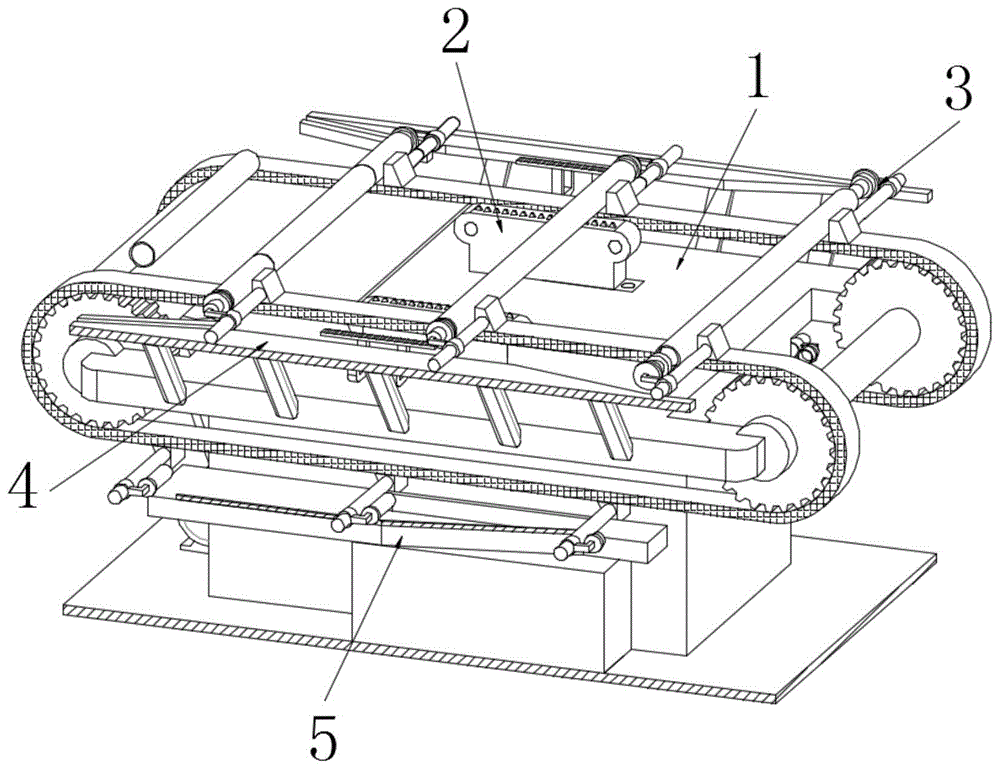
Referring to fig. 1 to 12, an apparatus for cutting and processing an end of a pipe for construction, comprising: the cutting conveying frame 1, the cutting clamp assembly 3 and the clamp driving mechanism 4;
a cutting mechanism 2 used for cutting the pipe is fixed on the cutting conveying frame 1 in parallel along the conveying direction;
the cutting clamp assemblies 3 are arranged in two groups, and the two groups of cutting clamp assemblies 3 are symmetrically and equidistantly fixed on the conveying belts 104 on the two sides of the cutting conveying frame 1;
the clamp driving mechanism 4 is fixed on the outer side of the cutting conveying frame 1 and attached to the cutting clamp assembly 3, the clamp driving mechanism 4 comprises three driving strokes, the first stroke is that the clamp driving mechanism 4 drives the cutting clamp assembly 3 to automatically fix the pipe conveyed on the cutting conveying frame 1, the second stroke is that the clamp driving mechanism 4 drives the cutting clamp assembly 3 to rotatably adjust the fixed pipe along the axis of the pipe, and the pipe is rotatably and circularly cut by matching with the cutting mechanism 2; and a third stroke, the clamp driving mechanism 4 drives the cutting clamp assembly 3 to separate the waste material at the end of the cut pipe from the pipe.
The working principle is as follows: when the pipe end is cut, the pipe is horizontally placed on the conveyer belt 104 on the cutting conveyer frame 1, the pipe is driven to move by the conveyer belt 104, when the pipe moves, the clamp driving mechanism 4 automatically drives the cutting clamp assembly 3 to symmetrically and centrally fix the two end heads of the pipe conveyed on the cutting conveying frame 1, then the cutting conveying frame 1 cooperates with the cutting clamp component 3 to continuously convey the fixed pipe, at the moment, the clamp driving mechanism 4 cooperates with the cutting clamp component 3 to drive the fixed pipe to rotate and adjust along the axis of the pipe, at the moment, the cutting mechanism 2 on the cutting conveying frame 1 realizes circular cutting when moving the end heads at the two ends of the pipe, the cutting conveying frame 1 continues conveying the pipe after the cutting is finished, at this moment, the clamp driving mechanism 4 is matched with the cutting clamp assembly 3 to be separated oppositely, and the waste materials at two ends of the cut pipe are separated from the cut pipe.
The cutting clamp assembly 3 comprises a guide rod 31 and an end fixing seat 33;
the guide rod 31 is vertically fixed on the conveying belt 104 of the cutting conveying frame 1 through a stop 34;
the end fixing seat 33 is slidably sleeved on the guide rod 31 through the connecting sleeve frame 32, and the end fixing seat 33 is rotatably connected with the connecting sleeve frame 32.
The tip holder 33 includes a connecting seat 333;
a limiting disc 332 is fixed at the tail end of the connecting seat 333, an adjusting gear 331 is connected to the outer side of the limiting disc 332, a first end head seat 335 and a second end head seat 336 are further connected to the upper front end of the connecting seat 333, and convex blocks 337 are movably embedded in the peripheral surfaces of the first end head seat 335 and the second end head seat 336;
a pressing mechanism 334 is disposed outside the connecting seat 333, and the pressing mechanism 334 is configured to automatically drive the protrusions 337 on the peripheral surfaces of the first end socket 335 and the second end socket 336 to protrude to fix the pipe when the head holder 33 is transported to the partial section of the fixture driving mechanism 4.
Further, the automatic driving cutting clamp assembly 3 of the clamp driving mechanism 4 symmetrically centers the ends of the two ends of the pipe conveyed on the cutting conveying frame 1 to be fixed by placing the pipe on the conveying belt 104 on the cutting conveying frame 1, the conveying belt 104 cooperates with the stopper 34 to convey the pipe, the pipe is placed to rotate, meanwhile, the end fixing seat 33 in the cutting clamp assembly 3 slides on the guide rod 31 under the action of the clamp driving mechanism 4 to be attached to the end of the pipe in an embedded mode and extrude the pressing mechanism 334, and the convex blocks 337 on the peripheral surfaces of the first end head seat 335 and the second end head seat 336 in the automatic driving end fixing seat 33 protrude to realize the fixation of the pipe.
The pressing mechanism 334 comprises a sliding sleeve 3341 and an adjusting core bar 3344;
the sliding sleeve 3341 is fixedly sleeved at the bottom end of the connecting seat 333, and a sliding seat 3342 is movably embedded and connected in the sliding sleeve 3341 through a return spring 3343, wherein the elastic force of the return spring 3343 is assembled to drive the sliding seat 3342 to move away from the limiting disc 332;
the adjusting core rod 3344 is movably embedded in the center of the connecting seat 333, the bottom end of the adjusting core rod 3344 is fixedly connected to the sliding seat 3342, the adjusting core rod 3344 penetrates through the first end head seat 335 and the second end head seat 336 and is connected to the bump 337 through the driving connecting rod 3345, and the driving connecting rod 3345 is rotatably hinged to the bump 337 and the adjusting core rod 3344.
Furthermore, the pressing mechanism 334 drives the protrusion 337 protruding from the peripheral surfaces of the first end head seat 335 and the second end head seat 336 in the end fixing seat 33 to fix the tube specifically, the end fixing seat 33 in the cutting clamp assembly 3 slides on the guide rod 31 under the action of the clamp driving mechanism 4 to be attached to the end of the tube in an embedded manner and to extrude the sliding seat 3342 in the pressing mechanism 334, the sliding seat 3342 drives the adjusting core rod 3344 to move, and the adjusting core rod 3344 cooperates with the driving connecting rod 3345 to drive the protrusion 337 protruding from the surface of the protrusion, so as to fix the tube.
The jig driving mechanism 4 includes an adjustment guide frame 41;
the adjusting guide frame 41 is horizontally fixed on the outer side of the cutting conveying frame 1, and the inner side of the adjusting guide frame 41 is sequentially provided with a protruding adjusting section 42, a horizontal conveying section 43 and a resetting separation section 44 along the conveying direction of the cutting conveying frame 1, wherein the protruding adjusting section 42, the horizontal conveying section 43 and the resetting separation section 44 are all attached to the limiting disc 332;
the protruding regulation section 42 is inclined and close to the cutting conveying frame 1 along the conveying direction of the cutting conveying frame 1, the horizontal conveying section 43 is arranged in parallel with the cutting conveying frame 1, and the reset separation section 44 is inclined and far away from the cutting conveying frame 1 along the conveying direction of the cutting conveying frame 1.
An adjusting toothed plate 45 is horizontally fixed on the inner side of the horizontal conveying section 43, the adjusting toothed plate 45 is meshed with the adjusting gear 331, and the position of the adjusting toothed plate 45 and the position of the cutting mechanism 2 are located in the same section of the cutting conveying frame 1;
a limit side frame 46 is horizontally fixed on the inner side of the reset separating section 44, wherein a strip-shaped guide opening for guiding and adjusting the limit disc 332 is formed between the limit side frame 46 and the reset separating section 44.
Further, the specific process of driving the cutting clamp assembly 3 by the clamp driving mechanism 4 is that the conveying belt 104 in the cutting conveying frame 1 drives the cutting clamp assembly 3 to move, and when the cutting clamp assembly 3 moves to the protruding adjusting section 42 of the adjusting guide frame 41 in the clamp driving mechanism 4, the protruding adjusting section 42 cooperates with the limiting disc 332 to drive the end fixing seat 33 to move on the guide rod 31 in the direction close to the cutting conveying frame 1;
when cutting jig subassembly 3 moves the horizontal transport section 43 of adjusting leading truck 41 in anchor clamps actuating mechanism 4, horizontal transport section 43 cooperation is spacing to end fixing base 33, make end fixing base 33 keep realizing carrying tubular product to the fixed state of tubular product, horizontal transport section 43's inboard horizontal fixation's regulation pinion rack 45 and end fixing base 33 in the transport adjust gear 331 intermeshing, make end fixing base 33 drive end fixing base 33 when removing and drive fixed tubular product and rotate along self axis, realize cooperating cutting mechanism 2 to rotate the circular cutting to fixed tubular product.
When the cutting clamp assembly 3 moves to the reset separation section 44 of the adjusting guide frame 41 in the clamp driving mechanism 4, the reset separation section 44 is matched with the limiting side frame 46 to form a strip-shaped guide opening to guide and limit the limiting disc 332, the end fixing seat 33 is driven to move on the guide rod 31 in the direction far away from the cutting conveying frame 1, the end fixing seat 33 is automatically separated, a pipe after cutting is finished drops, the cut pipe end waste materials are continuously conveyed on the end fixing seat 33, and the separation of the end waste materials and the pipe is realized.
The device also comprises a waste material blanking mechanism 5;
the waste blanking mechanism 5 comprises a horizontal supporting plate 51 and a waste collection box 53;
the horizontal supporting plate 51 is horizontally fixed at the bottom of the outer side of the cutting conveying frame 1, and a guide frame 52 for separation is welded on the horizontal supporting plate 51;
the waste collection box 53 is fixed at the tail end of the horizontal supporting plate 51, and a material receiving port 54 is arranged at the connecting position of the waste collection box 53 of the horizontal supporting plate 51.
Further, when the cut-off waste material at the end of the pipe is separated from the pipe, at this time, the reset spring 3343 automatically resets to drive the sliding seat 3342 to cooperate with the adjusting core rod 3344 to drive the protruding block 337 to reset, the cut-off waste material at the end of the pipe is sleeved on the end fixing seat 33 and cannot be fixed, meanwhile, the end fixing seat 33 drives the cut-off waste material at the end of the pipe to be conveyed to move to the horizontal supporting plate 51 on the waste blanking mechanism 5, the horizontal supporting plate 51 can support the end fixing seat 33 and the cut-off waste material at the end of the pipe, gravity is placed to influence the conveying of the conveying belt 104, the conveying belt 104 is protected from being damaged, meanwhile, the conveying stability of the conveying belt 104 is improved, when the conveying belt 104 drives the end fixing seat 33 and the cut-off waste material at the end of the pipe sleeved thereon to move on the horizontal supporting plate 51, the separation guide frame 52 on the horizontal supporting plate 51 is embedded between the limiting disc 332 and the waste material at the end of the pipe, and the tube end waste is driven by the separation guide frame 52 to slide off the end fixing seat 33 and fall into a waste collection box 53 from the material receiving opening 54 for collection.
The cutting carriage 1 includes a main body frame 101;
two ends of the main body frame 101 are symmetrically and rotatably connected with conveying rotating shafts 102, and two ends of the two conveying rotating shafts 102 are rotatably connected with conveying belts 104 through transmission gears 103;
one end of the main body frame 101 is fixed with a power unit 6, and an output shaft of the power unit 6 is in transmission connection with the conveying rotating shaft 102 through a transmission belt 7.
Further, when the cutting conveying frame 1 drives the conveying belt 104 to convey the pipe, the power unit 6 drives the conveying rotating shaft 102 to rotate through the transmission belt 7, the conveying rotating shaft 102 is matched with the transmission gear 103 to be rotatably connected with the conveying belt 104 to rotate, and the conveying belt 104 is driven to drive the pipe to convey.
The cutting mechanism 2 comprises a cutting machine frame 21, a cutting saw blade 22 and a reciprocating driving mechanism 23;
the top of the cutting frame 21 is horizontally provided with an adjusting groove 211, and two ends of the cutting frame 21 are symmetrically provided with arc-shaped interlayers 212;
the cutting saw blade 22 is horizontally arranged in the adjusting groove 211 in a sliding manner, the tops of two ends of the cutting saw blade 22 are connected with an elastic baffle 221 used for sealing the opening of the adjusting groove 211, the tail end of the elastic baffle 221 is movably embedded in the arc-shaped interlayer 212, and adjusting tooth grooves 222 are formed in the bottom of the cutting saw blade 22 at equal intervals;
a reciprocating drive mechanism 23 is fixed in the cutter carrier 21, and the reciprocating drive mechanism 23 is fitted for driving the cutting blade 22 in a horizontally reciprocating motion in the adjustment gullet 222.
Further, cutting mechanism 2 is carrying out the circular cutting to the tubular product specifically to do, reciprocating drive mechanism 23 drives cutting saw blade 22 and carries out reciprocating motion in adjustment tank 211, cut the tubular product through cutting saw blade 22, cutting saw blade 22 drives the elastic baffle 221 that cuts saw blade 22 both sides in step when reciprocating motion in adjustment tank 211 and removes in arc interlayer 212, carry out the closing cap through elastic baffle 221 to adjustment tank 211 opening, the metal fillings that produce when preventing to cut fall into adjustment tank 211, influence cutting saw blade 22 reciprocating motion, improve the stability that cutting saw blade 22 removed.
The reciprocating driving mechanism 23 comprises a sector driving fluted disc 231 and a driving disc 235;
the circular position of the sector driving fluted disc 231 is rotationally connected to the cutting frame 21 through the rotating shaft 232, the sector driving fluted disc 231 is meshed with the cutting saw blade 22 through the adjusting tooth slot 222, the tail end of the sector driving fluted disc 231 is integrally formed with an adjusting frame 233, and the adjusting frame 233 is provided with a strip-shaped hole 234;
a driving disc 235 is rotatably disposed in the cutter frame 21 by a driving unit, and an eccentric shaft 236 is disposed on the driving disc 235, wherein the eccentric shaft 236 is movably inserted in the strip hole 234.
Further, the reciprocating driving mechanism 23 drives the cutting saw blade 22 to reciprocate in the adjusting groove 211, specifically, the driving disk 235 is driven by the driving motor to rotate, the driving disk 235 drives the fan-shaped driving gear disk 231 to reciprocate along the rotating shaft 232 through the eccentric shaft 236 matching with the strip-shaped hole 234 formed in the adjusting bracket 233, and the fan-shaped driving gear disk 231 matches with the adjusting tooth slot 222 on the cutting saw blade 22 to drive the cutting saw blade 22 to reciprocate in the adjusting groove 211 to cut the pipe.
The pipe end cutting processing equipment for the building realizes the pipeline cutting of the pipe end, does not need the intermittent shutdown cutting, improves the cutting efficiency, simultaneously realizes the automatic centered fixed rotation cutting of the pipe, does not need the manual assistance of workers to fix and release, further improves the cutting efficiency, realizes the automatic separation and collection of waste materials and the pipe after the cutting is finished, does not need the manual sorting of the workers, lightens the labor intensity of the workers, realizes the relative fixation of the two sides of the pipe cutting position through the first end seat 335 and the second end seat 336 in the end fixing seat 33 when the pipe end is cut, ensures that the pipe and the end waste materials are kept fixed when the pipe is cut, improves the cutting quality, is convenient for secondary utilization, ensures that the pipe cutting surface is more level, and simultaneously realizes the support of the pipe cutting position when the pipe is cut, prevent that tubular product from cuting position department and appearing warping, this tubular product end cutting process equipment for building whole degree of automation is high, and the cutting operation is stable, convenient to use, and economic benefits is high.
In the description herein, references to the description of "one embodiment," "an example," "a specific example," etc., mean that a particular feature, structure, material, or characteristic described in connection with the embodiment or example is included in at least one embodiment or example of the invention. In this specification, the schematic representations of the terms used above do not necessarily refer to the same embodiment or example. Furthermore, the particular features, structures, materials, or characteristics described may be combined in any suitable manner in any one or more embodiments or examples.
The above description is only for the preferred embodiment of the present invention, but the scope of the present invention is not limited thereto, and any person skilled in the art should be considered to be within the technical scope of the present invention, and the technical solutions and the inventive concepts thereof according to the present invention should be equivalent or changed within the scope of the present invention.