CN112083258A - Intelligent fault detection device for power transformer - Google Patents
Intelligent fault detection device for power transformer Download PDFInfo
- Publication number
- CN112083258A CN112083258A CN202011001889.7A CN202011001889A CN112083258A CN 112083258 A CN112083258 A CN 112083258A CN 202011001889 A CN202011001889 A CN 202011001889A CN 112083258 A CN112083258 A CN 112083258A
- Authority
- CN
- China
- Prior art keywords
- module
- casing
- transformer
- shell
- detection device
- Prior art date
- Legal status (The legal status is an assumption and is not a legal conclusion. Google has not performed a legal analysis and makes no representation as to the accuracy of the status listed.)
- Pending
Links
- 238000001514 detection method Methods 0.000 title claims abstract description 33
- 238000004891 communication Methods 0.000 claims abstract description 41
- 238000012545 processing Methods 0.000 claims abstract description 40
- 230000017525 heat dissipation Effects 0.000 claims description 16
- 230000001681 protective effect Effects 0.000 claims description 16
- 238000000605 extraction Methods 0.000 claims description 15
- VYPSYNLAJGMNEJ-UHFFFAOYSA-N Silicium dioxide Chemical compound O=[Si]=O VYPSYNLAJGMNEJ-UHFFFAOYSA-N 0.000 claims description 14
- 239000000741 silica gel Substances 0.000 claims description 14
- 229910002027 silica gel Inorganic materials 0.000 claims description 14
- 238000009434 installation Methods 0.000 claims description 8
- 230000002159 abnormal effect Effects 0.000 claims description 7
- 238000001816 cooling Methods 0.000 claims description 4
- 238000012544 monitoring process Methods 0.000 claims description 4
- 230000005540 biological transmission Effects 0.000 claims description 3
- 239000004020 conductor Substances 0.000 claims description 3
- 230000002093 peripheral effect Effects 0.000 claims description 3
- 239000012780 transparent material Substances 0.000 claims description 3
- 238000005086 pumping Methods 0.000 claims description 2
- 238000010586 diagram Methods 0.000 description 4
- 238000012423 maintenance Methods 0.000 description 4
- 230000009471 action Effects 0.000 description 3
- 230000005236 sound signal Effects 0.000 description 3
- 230000000694 effects Effects 0.000 description 2
- 230000005611 electricity Effects 0.000 description 2
- 238000000034 method Methods 0.000 description 2
- 238000012986 modification Methods 0.000 description 2
- 230000004048 modification Effects 0.000 description 2
- 210000003437 trachea Anatomy 0.000 description 2
- 229910000838 Al alloy Inorganic materials 0.000 description 1
- 239000000956 alloy Substances 0.000 description 1
- 230000009286 beneficial effect Effects 0.000 description 1
- 230000008859 change Effects 0.000 description 1
- 238000004519 manufacturing process Methods 0.000 description 1
- 229920001296 polysiloxane Polymers 0.000 description 1
- 238000011084 recovery Methods 0.000 description 1
- 230000008439 repair process Effects 0.000 description 1
- 230000003068 static effect Effects 0.000 description 1
Images

Classifications
-
- G—PHYSICS
- G01—MEASURING; TESTING
- G01R—MEASURING ELECTRIC VARIABLES; MEASURING MAGNETIC VARIABLES
- G01R31/00—Arrangements for testing electric properties; Arrangements for locating electric faults; Arrangements for electrical testing characterised by what is being tested not provided for elsewhere
-
- G—PHYSICS
- G01—MEASURING; TESTING
- G01D—MEASURING NOT SPECIALLY ADAPTED FOR A SPECIFIC VARIABLE; ARRANGEMENTS FOR MEASURING TWO OR MORE VARIABLES NOT COVERED IN A SINGLE OTHER SUBCLASS; TARIFF METERING APPARATUS; MEASURING OR TESTING NOT OTHERWISE PROVIDED FOR
- G01D21/00—Measuring or testing not otherwise provided for
- G01D21/02—Measuring two or more variables by means not covered by a single other subclass
Landscapes
- Physics & Mathematics (AREA)
- General Physics & Mathematics (AREA)
- Housings And Mounting Of Transformers (AREA)
Abstract
Description
技术领域technical field
本发明涉及变压器检测技术领域,尤其涉及一种电力变压器故障智能检测装置。The invention relates to the technical field of transformer detection, in particular to an intelligent detection device for power transformer faults.
背景技术Background technique
电力变压器是一种静止的电气设备,是用来将某一数值的交流电压(电流)变成频率相同的另一种或几种数值不同的电压(电流)的设备;电力变压器是发电厂和变电所的主要设备之一。变压器的作用是多方面的不仅能升高电压把电能送到用电地区,还能把电压降低为各级使用电压,以满足用电的需要;变压器检修工作中,维修人员经常需要对电力变压器的故障原因进行检测;变压器故障时,除了变压器各侧电流、电压变化以及变压器内部声音变化外,变压器油箱内的油、气、温度等电量也会发生变化;维修人员需要对各种可能存在的故障一项一项的进行检查,操作繁琐且费时费力,对变压器的故障检修效率低下,大大增加电力系统恢复时长,给企业以及人们的生产生活带来不便;为此,本申请中提出一种电力变压器故障智能检测装置。A power transformer is a static electrical equipment that is used to convert a certain value of AC voltage (current) into another voltage (current) with the same frequency or different values; a power transformer is a power plant and One of the main equipment of the substation. The function of the transformer is multi-faceted. It can not only increase the voltage and send the electric energy to the electricity-consuming area, but also reduce the voltage to the voltage used at all levels to meet the needs of electricity consumption; in the transformer maintenance work, the maintenance personnel often need to repair the power transformer. When the transformer fails, in addition to the current and voltage changes on all sides of the transformer and the changes in the internal sound of the transformer, the oil, gas, temperature and other electricity in the transformer tank will also change; maintenance personnel need to Checking the faults one by one is cumbersome and time-consuming and labor-intensive. The efficiency of fault maintenance of the transformer is low, which greatly increases the recovery time of the power system and brings inconvenience to the production and life of enterprises and people. Therefore, this application proposes a Power transformer fault intelligent detection device.
发明内容SUMMARY OF THE INVENTION
(一)发明目的(1) Purpose of the invention
为解决背景技术中存在的技术问题,本发明提出一种电力变压器故障智能检测装置,本发明能高效快速的对变压器的故障进行分析,大大提高对变压器故障的检测效率。In order to solve the technical problems existing in the background art, the present invention proposes an intelligent detection device for power transformer faults. The present invention can analyze the faults of the transformers efficiently and quickly, and greatly improves the detection efficiency of the faults of the transformers.
(二)技术方案(2) Technical solutions
为解决上述问题,本发明提供了一种电力变压器故障智能检测装置,包括第一壳体、用于与变压器存有变压器油空仓连接的连接管、第二壳体、电路板、声音采集器和电流检测器;In order to solve the above problems, the present invention provides a power transformer fault intelligent detection device, which includes a first casing, a connecting pipe for connecting with the transformer oil empty tank, a second casing, a circuit board, a sound collector and current detector;
第一壳体内设有温度传感器和压力传感器,第一壳体与第二壳体连接,第一壳体上设有用于与连接管连接的进气部和用于与抽真空设备进气端通过气管连接的抽气部;抽气部上设有控制阀;A temperature sensor and a pressure sensor are arranged in the first shell, the first shell is connected with the second shell, and the first shell is provided with an air inlet part for connecting with the connecting pipe and for passing through the air inlet end of the vacuum pumping equipment. The air extraction part connected by the trachea; the air extraction part is provided with a control valve;
第二壳体的上端面设有按键模块和显示屏,第二壳体的侧端面设有用于与声音采集器配合的第一通信插口、用于与电流检测器配合的第二通信插口以及电源插口,第二壳体内并排设有多个支柱;The upper end face of the second casing is provided with a key module and a display screen, and the side end face of the second casing is provided with a first communication socket for matching with the sound collector, a second communication socket for matching with the current detector, and a power supply a socket, a plurality of pillars are arranged side by side in the second shell;
电路板位于第二壳体内,电路板连接多个支柱远离第二壳体内壁的一端,电路板上设有用于配合第一通信插口和第二通信插口的数据采集模块、转换器、数据处理模块、中央处理器、对比模块和用于存储以往变压器异常记录的数据库;The circuit board is located in the second casing, the circuit board is connected to one end of the plurality of pillars away from the inner wall of the second casing, and the circuit board is provided with a data acquisition module, a converter, and a data processing module for matching the first communication socket and the second communication socket , central processing unit, comparison module and database for storing past transformer abnormal records;
数据采集模块分别通讯连接温度传感器、压力传感器和转换器;转换器通信连接数据处理模块;数据处理模块通信连接中央处理器;中央处理器电性连接电源插口,中央处理器分别通信连接按键模块、显示屏、对比模块和用于存储以往变压器异常记录的数据库;数据库通信连接对比模块。The data acquisition module is respectively connected to the temperature sensor, the pressure sensor and the converter; the converter is connected to the data processing module; the data processing module is connected to the central processing unit; the central processing unit is electrically connected to the power socket, and the central processing unit is connected to the key module, Display screen, comparison module and database for storing abnormal records of previous transformers; database communication connection comparison module.
优选的,包括防护罩;Preferably, including a protective cover;
防护罩的一端通过铰链转动连接第二壳体,防护罩罩设在按键模块和显示屏的外侧,防护罩选用透明材质制成。One end of the protective cover is connected to the second shell through hinge rotation, the protective cover is arranged on the outside of the button module and the display screen, and the protective cover is made of transparent material.
优选的,第一壳体与第二壳体为一体化结构,第一壳体上设有把手。Preferably, the first casing and the second casing are of an integrated structure, and the first casing is provided with a handle.
优选的,第二壳体上用于与中央处理器数据传输连接的设有USB插口。Preferably, a USB socket is provided on the second casing for data transmission connection with the central processing unit.
优选的,包括用于与后台监控终端通讯连接的无线通讯模块;Preferably, it includes a wireless communication module for communicating with the background monitoring terminal;
无线通讯模块设置在电路板上,无线通讯模块与中央处理器通讯连接。The wireless communication module is arranged on the circuit board, and the wireless communication module is communicatively connected with the central processing unit.
优选的,进气部为圆筒形结构,进气部的外周面上设有外螺纹,进气部与连接管的端部螺纹配合连接。Preferably, the air intake portion has a cylindrical structure, an outer thread is provided on the outer peripheral surface of the air intake portion, and the air intake portion is threadedly connected to the end of the connecting pipe.
优选的,抽气部为圆筒形结构,抽气部与气管的端部螺纹配合连接。Preferably, the air extraction part has a cylindrical structure, and the air extraction part is connected with the end of the air pipe in a threaded fit.
优选的,包括多个支撑脚;多个支撑脚均匀设置在第二壳体的下端面。Preferably, a plurality of supporting feet are included; and the plurality of supporting feet are evenly arranged on the lower end surface of the second casing.
优选的,包括多个散热板;其中,第二壳体的内壁上设有多个用于安装多个散热板的安装槽;每个安装槽的底面均设有多个通孔;Preferably, it includes a plurality of heat dissipation plates; wherein, the inner wall of the second casing is provided with a plurality of installation grooves for installing the plurality of heat dissipation plates; the bottom surface of each installation groove is provided with a plurality of through holes;
多个支柱分别连接多个散热板,支柱与散热板一一对应,支柱选用导热材质制成。A plurality of pillars are respectively connected to a plurality of heat dissipation plates, the pillars are in one-to-one correspondence with the heat dissipation plates, and the pillars are made of thermally conductive materials.
优选的,每个散热板与支柱连接的端面上设有散热硅胶层;每个通孔内均填充散热硅胶,以在通孔内形成散热硅胶柱;每个散热硅胶柱的端面与第二壳体的端面平齐。Preferably, a heat-dissipating silica gel layer is provided on the end surface of each heat-dissipating plate connected to the pillar; each through-hole is filled with heat-dissipating silica gel to form a heat-dissipating silica gel column in the through-hole; the end surface of each heat-dissipating silica gel column is connected to the second shell The ends of the body are flush.
本发明的上述技术方案具有如下有益的技术效果:The above-mentioned technical scheme of the present invention has the following beneficial technical effects:
本发明中,在使用前需要对本装置进行了解,通过电流检测器对故障变压器电路中的电流进行检测并通过声音采集器对变压器内壁的声音进行检测,电流检测器和声音采集器分别通过数据线与第二通信插口以及第一通信插口连接;通过连接管将第一壳体的进气部与待检测变压器的变压器油仓连通;通过气管将第一壳体的抽气部与抽真空设备连接并将第一壳体内部的空气排出;In the present invention, it is necessary to understand the device before use. The current in the faulty transformer circuit is detected by the current detector, and the sound on the inner wall of the transformer is detected by the sound collector. The current detector and the sound collector respectively pass through the data line Connect with the second communication socket and the first communication socket; connect the air inlet part of the first casing with the transformer oil tank of the transformer to be tested through the connecting pipe; connect the air extraction part of the first casing with the vacuum equipment through the gas pipe and discharge the air inside the first shell;
使用时,将变压器的变压器油仓与第一壳体内部连通,变压器的变压器油仓内的气体在气压作用下快速流入第一壳体内,通过第一壳体内设有的温度传感器和压力传感器对变压器的变压器油仓内气体压力以及气体温度进行检查;数据采集模块采集温度传感器、压力传感器、声音采集器和电流检测器检测到的变压器油仓内的温度信号、变压器油仓内的气压信号、变压器内的声音信号以及变压器内电路电流的信号,上述采集的信号依次经过转换器和数据处理模块的处理后被中央处理器接收;中央处理器将上述处理后数据发送给对比模块;对比模块根据数据库内存储的以往变压器异常数据进行分析,得到变压器故障原因,并通过显示屏能对检测结果方便查看;本检测装置方便携带,使用方便,能大大提高对变压器故障的检测效率;本装置在使用时散热性好,能提高设备的使用寿命。When in use, the transformer oil tank of the transformer is communicated with the inside of the first shell, and the gas in the transformer oil tank of the transformer quickly flows into the first shell under the action of air pressure, and the temperature sensor and the pressure sensor provided in the first shell are connected to the first shell. Check the gas pressure and gas temperature in the transformer oil tank of the transformer; the data acquisition module collects the temperature signal in the transformer oil tank, the air pressure signal in the transformer oil tank, the temperature sensor, the pressure sensor, the sound collector and the current detector. The sound signal in the transformer and the signal of the circuit current in the transformer are received by the central processing unit after being processed by the converter and the data processing module in turn; the central processing unit sends the processed data to the comparison module; the comparison module is based on The abnormal data of the previous transformers stored in the database are analyzed to obtain the cause of the transformer fault, and the detection results can be easily viewed through the display screen; the detection device is portable and easy to use, and can greatly improve the detection efficiency of the transformer fault; the device is in use. It has good heat dissipation and can improve the service life of the equipment.
附图说明Description of drawings
图1为本发明提出的一种电力变压器故障智能检测装置的立体结构示意图。FIG. 1 is a schematic three-dimensional structure diagram of a power transformer fault intelligent detection device proposed by the present invention.
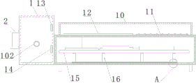
图2为本发明提出的一种电力变压器故障智能检测装置的结构示意图。FIG. 2 is a schematic structural diagram of a power transformer fault intelligent detection device proposed by the present invention.
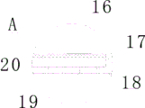
图3为本发明提出的一种电力变压器故障智能检测装置中A处局部放大的结构示意图。FIG. 3 is a schematic structural diagram of a partially enlarged part of A in a power transformer fault intelligent detection device proposed by the present invention.
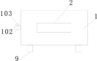
图4为本发明提出的一种电力变压器故障智能检测装置的左视图。FIG. 4 is a left side view of a power transformer fault intelligent detection device proposed by the present invention.
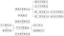
图5为本发明提出的一种电力变压器故障智能检测装置的原理框图。FIG. 5 is a schematic block diagram of a power transformer fault intelligent detection device proposed by the present invention.
附图标记:1、第一壳体;101、进气部;102、抽气部;2、把手;3、连接管;4、第二壳体;5、第一通信插口;6、第二通信插口;7、USB插口;8、电源插口;9、支撑脚;10、防护罩;11、按键模块;12、显示屏;13、温度传感器;14、压力传感器;15、电路板;16、支柱;17、安装槽;18、散热板;19、通孔;20、散热硅胶层;21、数据采集模块;22、转换器;23、数据处理模块;24、中央处理器;25、对比模块;26、数据库;27、声音采集器;28、电流检测器;29、无线通讯模块。Reference numerals: 1. First housing; 101. Air intake part; 102, Air extraction part; 2. Handle; 3. Connecting pipe; 4. Second housing; 5. First communication socket; 6. Second Communication socket; 7. USB socket; 8. Power socket; 9. Support feet; 10. Protective cover; 11. Button module; 12. Display screen; 13. Temperature sensor; 14. Pressure sensor; 15. Circuit board; 16. Pillar; 17. Installation slot; 18. Heat sink; 19, Through hole; 20, Heat dissipation silicone layer; 21, Data acquisition module; 22, Converter; 23, Data processing module; 24, Central processing unit; 25, Comparison module 26, database; 27, sound collector; 28, current detector; 29, wireless communication module.
具体实施方式Detailed ways
为使本发明的目的、技术方案和优点更加清楚明了,下面结合具体实施方式并参照附图,对本发明进一步详细说明。应该理解,这些描述只是示例性的,而并非要限制本发明的范围。此外,在以下说明中,省略了对公知结构和技术的描述,以避免不必要地混淆本发明的概念。In order to make the objectives, technical solutions and advantages of the present invention clearer, the present invention will be further described in detail below with reference to the specific embodiments and the accompanying drawings. It should be understood that these descriptions are exemplary only and are not intended to limit the scope of the invention. Also, in the following description, descriptions of well-known structures and techniques are omitted to avoid unnecessarily obscuring the concepts of the present invention.
如图1-5所示,本发明提出的一种电力变压器故障智能检测装置,包括第一壳体1、用于与变压器存有变压器油空仓连接的连接管3、第二壳体4、电路板15、声音采集器27和电流检测器28;其中,声音采集器27经过音频传感器穿入变压器内部;As shown in Figures 1-5, an intelligent detection device for power transformer faults proposed by the present invention includes a
第一壳体1内设有温度传感器13和压力传感器14,第一壳体1与第二壳体4连接,第一壳体1上设有用于与连接管3连接的进气部101和用于与抽真空设备进气端通过气管连接的抽气部102;抽气部102上设有第二控制阀;The
需要说明是的,连接管3与变压器油仓的加油端连接,从而通过连接管3将变压器油仓与第一壳体1的内部连通;抽真空设备用于在变压器油仓与第一壳体1的内部连通前将第一壳体1内部的空气抽出,使得第一壳体1内部气压降低,变压器油仓的气体在压力差作用下快速流入第一壳体1内部;It should be noted that, the connecting
第二壳体4的上端面设有按键模块11和显示屏12,第二壳体4的侧端面设有用于与声音采集器27配合的第一通信插口5、用于与电流检测器28配合的第二通信插口6以及电源插口8,第二壳体4内并排设有多个支柱16;The upper end face of the
电路板15位于第二壳体4内,电路板15连接多个支柱16远离第二壳体4内壁的一端,电路板15上设有用于配合第一通信插口5和第二通信插口6的数据采集模块21、转换器22、数据处理模块23、中央处理器24、对比模块25和用于存储以往变压器异常记录的数据库26;The
数据采集模块21分别通讯连接温度传感器13、压力传感器14和转换器22,数据采集模块21用于采集温度传感器13、压力传感器14、声音采集器27和电流检测器28检测到的变压器油仓内的温度信号、气压信号、变压器内的声音信号以及变压器内电路电流的信号,并将采集的上述信号发送给转换器22;The data acquisition module 21 is respectively connected to the
转换器22通信连接数据处理模块23,转换器22将接收到的电信号转换为数字信号,并将转换后信号发送给数据处理模块23;数据处理模块23通信连接中央处理器24;The converter 22 is communicatively connected to the data processing module 23, the converter 22 converts the received electrical signal into a digital signal, and sends the converted signal to the data processing module 23; the data processing module 23 is communicatively connected to the central processing unit 24;
中央处理器24电性连接电源插口8,中央处理器24分别通信连接按键模块11、显示屏12、对比模块25和用于存储以往变压器异常记录的数据库26;数据库26通信连接对比模块25;通过电源插口8连接外部电源为装置供电,中央处理器24将处理后的数据发送给对比模块25,对比模块25根据数据库26内存储的过往变压器异常数据进行分析,得到变压器故障原因,并在显示屏12上显示。The central processing unit 24 is electrically connected to the
本发明中,在使用前需要对本装置进行了解,通过电流检测器28对故障变压器电路中的电流进行检测并通过声音采集器27对变压器内壁的声音进行检测,电流检测器28和声音采集器27分别通过数据线与第二通信插口6以及第一通信插口5连接;通过连接管3将第一壳体1的进气部101与待检测变压器的变压器油仓连通;通过气管将第一壳体1的抽气部102与抽真空设备连接并将第一壳体1内部的空气排出;使用时,将变压器的变压器油仓与第一壳体1内部连通,变压器的变压器油仓内的气体在气压作用下快速流入第一壳体1内,通过第一壳体1内设有的温度传感器13和压力传感器14对变压器的变压器油仓内气体压力以及气体温度进行检查;数据采集模块21采集温度传感器13、压力传感器14、声音采集器27和电流检测器28检测到的变压器油仓内的温度信号、变压器油仓内的气压信号、变压器内的声音信号以及变压器内电路电流的信号,上述采集的信号依次经过转换器22和数据处理模块23的处理后被中央处理器24接收;中央处理器24将上述处理后数据发送给对比模块25;对比模块25根据数据库26内存储的以往变压器异常数据进行分析,得到变压器故障原因,并通过显示屏12能对检测结果方便查看;本检测装置方便携带,使用方便,能大大提高对变压器故障的检测效率。In the present invention, it is necessary to understand the device before use. The current in the faulty transformer circuit is detected by the current detector 28 and the sound on the inner wall of the transformer is detected by the sound collector 27. The current detector 28 and the sound collector 27 Connect with the
在一个可选的实施例中,包括防护罩10;In an optional embodiment, a
防护罩10的一端通过铰链转动连接第二壳体4,防护罩10罩设在按键模块11和显示屏12的外侧,防护罩10选用透明材质制成;设有的防护罩10对按键模块11和显示屏12进行防护,需要说明的是,防护罩10的另一端通过锁扣与第二壳体4固定;锁扣为现有市场上能直接选购的产品对此并不详细说明,通过锁扣将防护罩10与第二壳体4连接,避免防护罩10在外力下打开造成按键模块11和显示屏12的损坏。One end of the
在一个可选的实施例中,第一壳体1与第二壳体4为一体化结构,第一壳体1上设有把手2;通过设置的把手2方便对装置进行拎取。In an optional embodiment, the
在一个可选的实施例中,第二壳体4上用于与中央处理器24数据传输连接的设有USB插口,通过USB插口方便对检测结果拷贝至移动硬盘内。In an optional embodiment, a USB socket is provided on the
在一个可选的实施例中,包括用于与后台监控终端通讯连接的无线通讯模块29;In an optional embodiment, it includes a wireless communication module 29 for communicating with the background monitoring terminal;
无线通讯模块29设置在电路板15上,无线通讯模块29与中央处理器24通讯连接,通过设置的无线通讯模块29将检测结果发送至后台监控终端,以方便后台技术人员对变压器故障进行分析。The wireless communication module 29 is arranged on the
在一个可选的实施例中,进气部101为圆筒形结构,进气部101的外周面上设有外螺纹,进气部101与连接管3的端部螺纹配合连接。In an optional embodiment, the
在一个可选的实施例中,抽气部102为圆筒形结构,抽气部102与气管的端部螺纹配合连接。In an optional embodiment, the
在一个可选的实施例中,包括多个支撑脚9;多个支撑脚9均匀设置在第二壳体4的下端面。In an optional embodiment, a plurality of supporting
在一个可选的实施例中,包括多个散热板18;其中,第二壳体4的内壁上设有多个用于安装多个散热板18的安装槽17;每个安装槽17的底面均设有多个通孔19;In an optional embodiment, a plurality of
多个支柱16分别连接多个散热板18,支柱16与散热板18一一对应,支柱16选用导热材质制成;The plurality of
进一步的,支柱16选用但不限于铝合金材质制成;通过设置的散热板18将第二壳体4内部用电设备运行产生的高温散发出去,多个通孔19与外界连通,外界空气能之间与散热板18接触以将散热板18上的热能带走,达到对第二壳体4内部散热的效果,提高本装置的使用寿命。Further, the
在一个可选的实施例中,每个散热板18与支柱16连接的端面上设有散热硅胶层20;每个通孔19内均填充散热硅胶,以在通孔19内形成散热硅胶柱;每个散热硅胶柱的端面与第二壳体4的端面平齐;在散热板18端面设有的散热硅胶层20提高支柱16与散热板18之间的导热效率;在通孔19内填充散热硅胶提高对散热板18的散热效率。In an optional embodiment, a heat-dissipating
应当理解的是,本发明的上述具体实施方式仅仅用于示例性说明或解释本发明的原理,而不构成对本发明的限制。因此,在不偏离本发明的精神和范围的情况下所做的任何修改、等同替换、改进等,均应包含在本发明的保护范围之内。此外,本发明所附权利要求旨在涵盖落入所附权利要求范围和边界、或者这种范围和边界的等同形式内的全部变化和修改例。It should be understood that the above-mentioned specific embodiments of the present invention are only used to illustrate or explain the principle of the present invention, but not to limit the present invention. Therefore, any modifications, equivalent replacements, improvements, etc. made without departing from the spirit and scope of the present invention should be included within the protection scope of the present invention. Furthermore, the appended claims of this invention are intended to cover all changes and modifications that fall within the scope and boundaries of the appended claims, or the equivalents of such scope and boundaries.
Claims (10)
Priority Applications (1)
| Application Number | Priority Date | Filing Date | Title |
|---|---|---|---|
| CN202011001889.7A CN112083258A (en) | 2020-09-22 | 2020-09-22 | Intelligent fault detection device for power transformer |
Applications Claiming Priority (1)
| Application Number | Priority Date | Filing Date | Title |
|---|---|---|---|
| CN202011001889.7A CN112083258A (en) | 2020-09-22 | 2020-09-22 | Intelligent fault detection device for power transformer |
Publications (1)
| Publication Number | Publication Date |
|---|---|
| CN112083258A true CN112083258A (en) | 2020-12-15 |
Family
ID=73739543
Family Applications (1)
| Application Number | Title | Priority Date | Filing Date |
|---|---|---|---|
| CN202011001889.7A Pending CN112083258A (en) | 2020-09-22 | 2020-09-22 | Intelligent fault detection device for power transformer |
Country Status (1)
| Country | Link |
|---|---|
| CN (1) | CN112083258A (en) |
Cited By (2)
| Publication number | Priority date | Publication date | Assignee | Title |
|---|---|---|---|---|
| CN112698139A (en) * | 2020-12-28 | 2021-04-23 | 五邑大学 | Transformer remote detection device |
| CN114002537A (en) * | 2022-01-05 | 2022-02-01 | 山东广域科技有限责任公司 | Power equipment state detection device for transformer substation with diagnosis function |
Citations (4)
| Publication number | Priority date | Publication date | Assignee | Title |
|---|---|---|---|---|
| CN104793070A (en) * | 2015-03-12 | 2015-07-22 | 国网浙江海盐县供电公司 | Intelligent distribution transformer online monitoring system |
| CN207853564U (en) * | 2018-01-04 | 2018-09-11 | 福建省建瓯市荣飞建筑劳务有限公司 | A kind of transformer station high-voltage side bus parameter monitoring terminal |
| CN208224394U (en) * | 2018-06-04 | 2018-12-11 | 冀强 | A kind of distributing transformer monitoring device |
| CN209639764U (en) * | 2019-04-26 | 2019-11-15 | 仁诚建设有限公司 | A power transformer fault intelligent detection device |
-
2020
- 2020-09-22 CN CN202011001889.7A patent/CN112083258A/en active Pending
Patent Citations (4)
| Publication number | Priority date | Publication date | Assignee | Title |
|---|---|---|---|---|
| CN104793070A (en) * | 2015-03-12 | 2015-07-22 | 国网浙江海盐县供电公司 | Intelligent distribution transformer online monitoring system |
| CN207853564U (en) * | 2018-01-04 | 2018-09-11 | 福建省建瓯市荣飞建筑劳务有限公司 | A kind of transformer station high-voltage side bus parameter monitoring terminal |
| CN208224394U (en) * | 2018-06-04 | 2018-12-11 | 冀强 | A kind of distributing transformer monitoring device |
| CN209639764U (en) * | 2019-04-26 | 2019-11-15 | 仁诚建设有限公司 | A power transformer fault intelligent detection device |
Cited By (3)
| Publication number | Priority date | Publication date | Assignee | Title |
|---|---|---|---|---|
| CN112698139A (en) * | 2020-12-28 | 2021-04-23 | 五邑大学 | Transformer remote detection device |
| CN112698139B (en) * | 2020-12-28 | 2024-06-04 | 五邑大学 | A remote detection device for transformer |
| CN114002537A (en) * | 2022-01-05 | 2022-02-01 | 山东广域科技有限责任公司 | Power equipment state detection device for transformer substation with diagnosis function |
Similar Documents
| Publication | Publication Date | Title |
|---|---|---|
| CN204165670U (en) | A kind of SAW Temperature Sensors for outdoor high voltage environment | |
| CN104347205B (en) | Low-cost intelligent medium-pressure composite insulation sheath zinc oxide arrester | |
| WO2023217053A1 (en) | Multiple-in-one sensing apparatus for monitoring end screen of transformer bushing | |
| CN106569113A (en) | Vacuum adsorption type partial discharge probe device | |
| CN207232261U (en) | A kind of loop resistance tests system | |
| CN204189543U (en) | Class composite insulation outer coat zinc oxide arrester is pressed in a kind of low cost intelligent type | |
| CN205484656U (en) | Be used for 95598 automatic power failure detection device of electric power | |
| CN104459496A (en) | 220kV long cable voltage withstand test wireless control system and control method thereof | |
| CN206618828U (en) | A kind of discharge signal monitoring system of switch cubicle | |
| CN210982662U (en) | Built-in ultrahigh frequency partial discharge signal detection sensor | |
| CN110191601B (en) | Computer network monitoring device | |
| CN206420940U (en) | Battery voltage measuring instrument | |
| CN216593819U (en) | Temperature anomaly monitoring device at motor lead wire | |
| CN107044889B (en) | The thermometry of high-voltage arrester | |
| CN214473721U (en) | Built-in multispectral sensing device for GIS | |
| CN218386857U (en) | Power supply unit suitable for FTU | |
| CN204439686U (en) | A kind of ammeter box with monitoring function | |
| CN103427488A (en) | Box-type transformer monitoring system | |
| CN211014526U (en) | A high-voltage switch cabinet partial discharge ozone online monitoring device | |
| CN207717127U (en) | A kind of information machine room power equipment performance monitoring apparatus | |
| CN208385194U (en) | A kind of highly-safe voltage transformer | |
| CN209590203U (en) | A kind of capacitance type equipment insulation monitoring device | |
| CN213275682U (en) | Structure of a multimeter for house inspection | |
| CN218068126U (en) | A voltage detection and alarm device capable of storing massive bus voltage data | |
| CN209182302U (en) | A kind of high-tension switch cabinet ozone concentration detection device |
Legal Events
| Date | Code | Title | Description |
|---|---|---|---|
| PB01 | Publication | ||
| PB01 | Publication | ||
| SE01 | Entry into force of request for substantive examination | ||
| SE01 | Entry into force of request for substantive examination | ||
| RJ01 | Rejection of invention patent application after publication | ||
| RJ01 | Rejection of invention patent application after publication |
Application publication date: 20201215 |