CN112066569A - Water storage type metal inner container solar heat collecting pipe - Google Patents
Water storage type metal inner container solar heat collecting pipe Download PDFInfo
- Publication number
- CN112066569A CN112066569A CN202010906817.0A CN202010906817A CN112066569A CN 112066569 A CN112066569 A CN 112066569A CN 202010906817 A CN202010906817 A CN 202010906817A CN 112066569 A CN112066569 A CN 112066569A
- Authority
- CN
- China
- Prior art keywords
- water storage
- pipe
- medium
- tube
- wall
- Prior art date
- Legal status (The legal status is an assumption and is not a legal conclusion. Google has not performed a legal analysis and makes no representation as to the accuracy of the status listed.)
- Pending
Links
- XLYOFNOQVPJJNP-UHFFFAOYSA-N water Substances O XLYOFNOQVPJJNP-UHFFFAOYSA-N 0.000 title claims abstract description 127
- 229910052751 metal Inorganic materials 0.000 title claims abstract description 27
- 239000002184 metal Substances 0.000 title claims abstract description 27
- 230000005540 biological transmission Effects 0.000 claims abstract description 16
- 238000010521 absorption reaction Methods 0.000 claims abstract description 5
- 238000007789 sealing Methods 0.000 claims abstract description 5
- 239000011248 coating agent Substances 0.000 claims description 7
- 238000000576 coating method Methods 0.000 claims description 7
- RYGMFSIKBFXOCR-UHFFFAOYSA-N Copper Chemical compound [Cu] RYGMFSIKBFXOCR-UHFFFAOYSA-N 0.000 claims description 3
- 239000006244 Medium Thermal Substances 0.000 claims description 3
- 229910052802 copper Inorganic materials 0.000 claims description 3
- 239000010949 copper Substances 0.000 claims description 3
- 229910001220 stainless steel Inorganic materials 0.000 claims description 3
- 239000010935 stainless steel Substances 0.000 claims description 3
- 238000004519 manufacturing process Methods 0.000 abstract description 7
- 238000000034 method Methods 0.000 abstract description 3
- 238000010438 heat treatment Methods 0.000 description 11
- 238000009434 installation Methods 0.000 description 6
- 230000000694 effects Effects 0.000 description 5
- 230000009286 beneficial effect Effects 0.000 description 2
- 238000005034 decoration Methods 0.000 description 2
- 239000011521 glass Substances 0.000 description 2
- 239000000463 material Substances 0.000 description 2
- 238000012986 modification Methods 0.000 description 2
- 230000004048 modification Effects 0.000 description 2
- 238000012546 transfer Methods 0.000 description 2
- 229910052782 aluminium Inorganic materials 0.000 description 1
- XAGFODPZIPBFFR-UHFFFAOYSA-N aluminium Chemical compound [Al] XAGFODPZIPBFFR-UHFFFAOYSA-N 0.000 description 1
- 229910052788 barium Inorganic materials 0.000 description 1
- DSAJWYNOEDNPEQ-UHFFFAOYSA-N barium atom Chemical compound [Ba] DSAJWYNOEDNPEQ-UHFFFAOYSA-N 0.000 description 1
- 238000002474 experimental method Methods 0.000 description 1
- 239000007769 metal material Substances 0.000 description 1
- 239000000203 mixture Substances 0.000 description 1
- 238000012544 monitoring process Methods 0.000 description 1
- 230000002035 prolonged effect Effects 0.000 description 1
- 230000005855 radiation Effects 0.000 description 1
- 229910052709 silver Inorganic materials 0.000 description 1
- 239000004332 silver Substances 0.000 description 1
- 238000004804 winding Methods 0.000 description 1
Images


Classifications
-
- F—MECHANICAL ENGINEERING; LIGHTING; HEATING; WEAPONS; BLASTING
- F24—HEATING; RANGES; VENTILATING
- F24S—SOLAR HEAT COLLECTORS; SOLAR HEAT SYSTEMS
- F24S10/00—Solar heat collectors using working fluids
- F24S10/40—Solar heat collectors using working fluids in absorbing elements surrounded by transparent enclosures, e.g. evacuated solar collectors
-
- F—MECHANICAL ENGINEERING; LIGHTING; HEATING; WEAPONS; BLASTING
- F24—HEATING; RANGES; VENTILATING
- F24S—SOLAR HEAT COLLECTORS; SOLAR HEAT SYSTEMS
- F24S10/00—Solar heat collectors using working fluids
- F24S10/30—Solar heat collectors using working fluids with means for exchanging heat between two or more working fluids
-
- F—MECHANICAL ENGINEERING; LIGHTING; HEATING; WEAPONS; BLASTING
- F24—HEATING; RANGES; VENTILATING
- F24S—SOLAR HEAT COLLECTORS; SOLAR HEAT SYSTEMS
- F24S10/00—Solar heat collectors using working fluids
- F24S10/70—Solar heat collectors using working fluids the working fluids being conveyed through tubular absorbing conduits
- F24S10/74—Solar heat collectors using working fluids the working fluids being conveyed through tubular absorbing conduits the tubular conduits are not fixed to heat absorbing plates and are not touching each other
- F24S10/744—Solar heat collectors using working fluids the working fluids being conveyed through tubular absorbing conduits the tubular conduits are not fixed to heat absorbing plates and are not touching each other the conduits being helically coiled
-
- F—MECHANICAL ENGINEERING; LIGHTING; HEATING; WEAPONS; BLASTING
- F24—HEATING; RANGES; VENTILATING
- F24S—SOLAR HEAT COLLECTORS; SOLAR HEAT SYSTEMS
- F24S10/00—Solar heat collectors using working fluids
- F24S10/70—Solar heat collectors using working fluids the working fluids being conveyed through tubular absorbing conduits
- F24S10/75—Solar heat collectors using working fluids the working fluids being conveyed through tubular absorbing conduits with enlarged surfaces, e.g. with protrusions or corrugations
-
- F—MECHANICAL ENGINEERING; LIGHTING; HEATING; WEAPONS; BLASTING
- F24—HEATING; RANGES; VENTILATING
- F24S—SOLAR HEAT COLLECTORS; SOLAR HEAT SYSTEMS
- F24S70/00—Details of absorbing elements
- F24S70/20—Details of absorbing elements characterised by absorbing coatings; characterised by surface treatment for increasing absorption
-
- F—MECHANICAL ENGINEERING; LIGHTING; HEATING; WEAPONS; BLASTING
- F24—HEATING; RANGES; VENTILATING
- F24S—SOLAR HEAT COLLECTORS; SOLAR HEAT SYSTEMS
- F24S80/00—Details, accessories or component parts of solar heat collectors not provided for in groups F24S10/00-F24S70/00
- F24S80/70—Sealing means
-
- Y—GENERAL TAGGING OF NEW TECHNOLOGICAL DEVELOPMENTS; GENERAL TAGGING OF CROSS-SECTIONAL TECHNOLOGIES SPANNING OVER SEVERAL SECTIONS OF THE IPC; TECHNICAL SUBJECTS COVERED BY FORMER USPC CROSS-REFERENCE ART COLLECTIONS [XRACs] AND DIGESTS
- Y02—TECHNOLOGIES OR APPLICATIONS FOR MITIGATION OR ADAPTATION AGAINST CLIMATE CHANGE
- Y02E—REDUCTION OF GREENHOUSE GAS [GHG] EMISSIONS, RELATED TO ENERGY GENERATION, TRANSMISSION OR DISTRIBUTION
- Y02E10/00—Energy generation through renewable energy sources
- Y02E10/40—Solar thermal energy, e.g. solar towers
- Y02E10/44—Heat exchange systems
Landscapes
- Engineering & Computer Science (AREA)
- Chemical & Material Sciences (AREA)
- Physics & Mathematics (AREA)
- Life Sciences & Earth Sciences (AREA)
- Sustainable Development (AREA)
- Sustainable Energy (AREA)
- Thermal Sciences (AREA)
- Combustion & Propulsion (AREA)
- Mechanical Engineering (AREA)
- General Engineering & Computer Science (AREA)
- Dispersion Chemistry (AREA)
- Heat-Pump Type And Storage Water Heaters (AREA)
Abstract
The invention provides a water storage type metal liner solar heat collecting tube which comprises a water storage tube, a medium tube and a light transmitting tube, wherein a water storage cavity is formed in the water storage tube, and a water inlet tube and a water outlet tube are arranged in the water storage cavity; the medium pipe is sleeved outside the water storage pipe, the head of the medium pipe is sealed, the tail of the medium pipe is necked down and is in sealing connection with the water storage pipe, the outer wall of the medium pipe is attached with a heat absorption film, and a medium is filled between the inner wall of the medium pipe and the outer wall of the water storage pipe; the light transmission tube is sleeved outside the medium tube, the head of the light transmission tube is sealed, the tail of the light transmission tube is necked down and is in sealing connection with the water storage tube or the medium tube, and a vacuum cavity is arranged between the inner wall of the light transmission tube and the outer wall of the medium tube. The water storage type solar heat collecting pipe with the metal inner container has the advantages of simple process, low manufacturing cost, high heat utilization rate and good safety.
Description
Technical Field
The invention relates to a solar heat collecting pipe, in particular to a water storage type metal liner solar heat collecting pipe.
Background
Solar heat collection is a core element of a solar water heater, is known as the heart of the solar water heater, and the quality of the heat collection tube directly influences the service life and the performance of the solar water heater. The traditional solar water heater comprises a water tank and a plurality of heat collecting pipes, wherein the water tank is transversely arranged, the heat collecting pipes are obliquely arranged at the lower end of the water tank, heat conducting parts of the heat collecting pipes extend into the water tank for heat exchange, the heat utilization rate is extremely low, and the inner pipe and the outer pipe are both made of glass pipes, so that the heat conductivity is poor, the heat loss is serious, the heat utilization rate is further reduced, and the integral heating effect of the solar water heater is poor and unstable; and moreover, the two ends of the heat collecting pipes on the market are fixed, when the heat collecting pipes are heated and expanded, the expansion amount is different, so that the heat collecting pipes are easy to crack, and the product is scrapped or even the personal safety is threatened.
Disclosure of Invention
【1】 Technical problem to be solved
The invention aims to solve the technical problem of providing a water storage type metal liner solar heat collecting pipe with quick heat exchange and high heat utilization rate.
【2】 Technical scheme for solving problems
The invention provides a water storage type metal liner solar heat collecting pipe, which comprises:
the water storage device comprises a water storage pipe 11, a water storage cavity 10 is formed in the water storage pipe 11, a water inlet pipe 41 and a water outlet pipe 42 which extend out of the water storage pipe are arranged in the water storage cavity, and the water inlet pipe extends to the bottom of the water storage cavity;
the medium pipe 12 is sleeved outside the water storage pipe, the head of the medium pipe is sealed, the tail of the medium pipe is necked down and is connected with the water storage pipe in a sealing way, a heat absorption film 13 for absorbing solar energy is attached to the outer wall of the medium pipe, a gap is formed between the inner wall of the medium pipe and the outer wall of the water storage pipe to form a sealed medium cavity 1112, and a medium for heat conduction is filled in the medium cavity;
and the light transmitting tube 14 is sleeved outside the medium tube, the head of the light transmitting tube is sealed, the tail of the light transmitting tube is necked down and is in sealing connection with the water storage tube or the medium tube, and a gap is arranged between the inner wall of the light transmitting tube and the outer wall of the medium tube and is vacuumized to form a vacuum cavity 1314.
Further, the heat absorbing film can be replaced by a high temperature film.
Further, the water storage pipe is made of stainless steel or copper.
Further, a bracket 31 is arranged at the head of the vacuum cavity, and a getter is arranged on the bracket.
Further, the side wall of the vacuum chamber is provided with a getter coating 32.
Further, an expansion space V is arranged in the medium cavity, and the expansion space V meets the following requirements:
V≥v1*dT*a;
in the formula, v1 is the medium filling volume, dT is the temperature change amount, and a is the medium thermal conductivity.
Further, the ratio of the outer diameters of the water storage pipe and the light transmission pipe is greater than or equal to 2/5 and less than or equal to 4/5.
Further, the thickness of the medium cavity is larger than the wall thickness of the medium pipe.
Further, the inner wall of the water storage pipe or the outer wall of the water storage pipe or the inner wall of the medium pipe is provided with heat conducting fins 5, and the heat conducting fins are strips which are uniformly distributed along the circumferential direction of the axis or spiral which are wound around the side wall.
Further, the vacuum degree of the vacuum cavity is more than or equal to 10-3Pa。
【3】 Advantageous effects
The water storage type metal inner container solar heat collecting tube adopts single-side fixation, is beneficial to the connection and fixation between the inner tube and the outer tube, avoids the problem that the double ends of the traditional heat collecting tube are fixed and cracked due to heating, and improves the use stability and safety of the product; the built-in water tank is adopted, the whole volume is reduced, the flexibility is high, a certain number of heat collecting pipes can be connected in series according to the requirement, and the use flexibility is good; the medium cavity is additionally arranged, so that the heat energy utilization rate and the heating efficiency are improved, andthe heat conducting fins are arranged, so that the heating efficiency and the heat energy utilization rate are further improved; the size ratio is optimally designed, an optimal balance point is formed among the volume, the cost and the heat exchange, the production cost is reduced, the heat exchange efficiency and the heating effect are improved, the vacuum cavity is high in vacuum, the vacuum maintaining time is long, and the vacuum degree of the vacuum cavity is not lower than 10 within 8-10 years-3Pa。
Drawings
FIG. 1 is a schematic structural view of a water storage type metal liner solar heat collecting tube of the present invention;
FIG. 2 is a cross-sectional view of a solar heat collecting tube with a water storage type metal liner of the present invention;
FIG. 3 is a schematic view of the installation of a first embodiment of the heat conducting fin of the water storage type metal liner solar heat collecting tube of the present invention;
FIG. 4 is a schematic view of the installation of a second embodiment of the heat conducting fin of the water storage type metal liner solar heat collecting tube of the present invention;
FIG. 5 is a schematic view of the installation of a third embodiment of the heat conducting fin of the water storage type metal liner solar heat collecting tube of the present invention;
FIG. 6 is a schematic view of the installation of the heat conducting fin of the water storage type metal liner solar heat collecting tube of the fourth embodiment of the present invention;
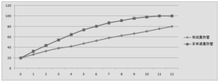
fig. 7 is a graph comparing the heating of the solar heat collecting pipe with the traditional solar pipe.
Detailed Description
The following describes embodiments of the present invention in detail with reference to the accompanying drawings.
Referring to fig. 1 to 2, the invention provides a water storage type solar heat collecting tube with a metal liner, which comprises a water storage tube, a medium tube 12 and a light transmitting tube 14; the water storage pipe 11 is used for storing water, the whole water storage pipe is cylindrical, namely the cross section is circular, the head of the water storage pipe is sealed in a hemispherical shape, a water storage cavity 10 is formed in the water storage pipe 11, water to be heated is filled in the water storage cavity, a water inlet pipe 41 and a water outlet pipe 42 which extend out of the water storage pipe are arranged in the water storage cavity, the water inlet pipe extends to the bottom of the water storage cavity, the water outlet pipe is positioned at the upper end of the water storage cavity, and cold water enters from the lower end of the water storage cavity and hot water is discharged from the upper end of the; book (I)In the application, the water storage pipe is made of metal, so that the water storage pipe is convenient to process, low in material cost and manufacturing cost, preferably made of stainless steel or copper, and capable of comprehensively considering and selecting proper metal materials according to different use requirements or product quantity; the medium pipe 12 is sleeved outside the water storage pipe, is coaxially arranged with the water storage pipe, is integrally cylindrical, and has a hemispherical seal at the head, the tail part of the medium pipe is necked down and is hermetically connected with the water storage pipe, and the other end of the medium pipe is not contacted with the water storage pipe in a fixed mode at one end, so that the connection of the two pipes is more convenient, and the manufacturing cost is greatly reduced; the outer wall of the medium pipe is attached with a heat absorption film 13 for absorbing solar energy, a gap is formed between the inner wall of the medium pipe and the outer wall of the water storage pipe to form a sealed medium cavity 1112, a medium for heat conduction is filled in the medium cavity, the medium is heat conduction oil, and the heat conduction oil is not the invention point of the application and is not described in detail; the light transmission pipe 14 is sleeved outside the medium pipe, is coaxial with the medium pipe, is cylindrical as a whole, namely, the cross section is circular, the head part of the light transmission pipe is sealed in a hemispherical shape, the tail part of the light transmission pipe is necked down and is hermetically connected with the water storage pipe or the medium pipe, the light transmission pipe is made of glass, the light transmission pipe is made of a material different from the water storage pipe or the medium pipe, the light transmission pipe is connected with the two pipes more conveniently in a mode that one end of the light transmission pipe is fixed, the other end of the light transmission pipe is not contacted with the water storage pipe or the medium pipe, the two pipes are connected more conveniently, the manufacturing cost is greatly reduced, the problem that the two ends of the traditional heat collecting pipe are fixed and are cracked due to heating is avoided, the quality reliability and the-3Pa; when the solar heat collector works, the solar tube is obliquely arranged at a certain angle, sunlight penetrates through the euphotic layer to irradiate on the heat absorbing film, and the heat absorbing film (the medium tube) and the euphotic layer are in a vacuum state, so that only heat radiation is realized, heat conduction is avoided, heat loss caused by heat conduction is avoided, the heat absorbing film absorbs heat and transfers the heat to heat conducting oil in a medium cavity in contact with the heat absorbing film, the heat conducting oil is heated, and the heat of the heat conducting oil is transferred to water in the water storage cavity through the side wall of the water storage tube, so that a heat transfer process; in order to ensure the vacuum degree in the vacuum chamber, prolong the service life and avoid heat loss, the vacuum chamber is internally provided with a vacuum chamberThe head of the cavity is provided with a bracket 31, and a getter is arranged on the bracket; the vacuum degree can be maintained in another mode, namely, the side wall of the vacuum cavity is provided with the air suction coating 32 which is a mixture of barium and aluminum, the whole air suction coating is silver, the air suction coating can play a role in air suction, and the coating changes color after absorbing a certain amount of air to achieve a certain monitoring effect, so that a plurality of coating blocks can be sprayed inside during manufacturing, and can be activated at the later stage according to requirements, and the service life of a product is greatly prolonged; it ensures that the vacuum degree in the vacuum cavity is kept for a long time, and the vacuum degree is not lower than 10 within 8-10 years-3Pa; because the heat conduction oil has certain expansion amount, an expansion space V is arranged in the medium cavity, namely the medium cavity is not filled with the heat conduction oil when being filled with the medium, and the expansion space V meets the following requirements:
V≥v1*dT*a;
in the formula, v1 is the medium filling volume, dT is the temperature change amount, and a is the medium thermal conductivity.
In order to achieve the optimal ratio of the volume to the heat energy absorption, the ratio of the outer diameter between the water storage pipe and the light transmission pipe in the embodiment is greater than or equal to 2/5 and less than or equal to 4/5, preferably, the ratio of the outer diameter between the water storage pipe and the light transmission pipe is 3/5, and the thickness of the medium cavity is greater than the wall thickness of the medium pipe, wherein in the application, the thickness of the medium pipe is 1-3mm, the thickness of the water storage pipe is 2-5mm, and the thickness (radial direction) of the medium cavity is 10-20 mm; in order to further improve heat utilization efficiency, be equipped with conducting strip 5 in the inner wall of standpipe or the outer wall of standpipe or the inner wall of medium pipe in this application, this conducting strip is the strip of following axis circumference equipartition or winds the spiral of lateral wall winding.
Several installation modes are respectively explained below;
in the first embodiment, referring to fig. 3, in this embodiment, the heat conducting fins are strip-shaped, the length direction of the heat conducting fins is parallel to the axis direction, and a plurality of heat conducting fins are uniformly distributed on the inner wall of the medium pipe circumferentially around the axis;
in the second embodiment, referring to fig. 4, in this embodiment, the heat conducting fins are strip-shaped, the length direction of the heat conducting fins is parallel to the axis direction, and a plurality of heat conducting fins are uniformly distributed on the outer wall of the water storage pipe circumferentially around the axis;
in the third embodiment, referring to fig. 5, the heat conducting fins are strip-shaped, the length direction of the heat conducting fins is parallel to the axis direction, the number of the heat conducting fins is multiple, the heat conducting fins are circumferentially and uniformly distributed on the outer wall of the water storage pipe and the inner wall of the medium pipe around the axis, and the heat conducting fins on the outer wall of the water storage pipe and the heat conducting fins on the inner wall of the medium pipe are arranged in a staggered;
in the fourth embodiment, referring to fig. 6, the heat conducting fins are strip-shaped, the length direction of the heat conducting fins is parallel to the axis direction, and the heat conducting fins are multiple and are uniformly distributed on the inner wall of the water storage pipe circumferentially around the axis;
and example 1 to example 4 may be used in combination;
the heat conducting fin can also be in a spiral shape, and the installation mode comprises the following steps;
in the fifth embodiment, the heat conducting plate is a spiral shape (not shown), and may be installed on the inner wall of the medium pipe, the outer wall of the water storage pipe, or the inner wall of the water storage pipe, or may be installed at two or three positions.
Meanwhile, the solar tube in the application is compared with a traditional solar tube in an experiment, under the condition that the water storage capacity is the same (100L), the temperature change condition (the initial temperature of water temperature is 20 degrees), water temperature data are sampled once per hour, a curve graph is drawn according to the sampled data, and referring to fig. 7, (the horizontal axis is time, the unit h, the vertical axis is water temperature, and the unit is ℃), the water temperature of the traditional solar tube is shown in the graph as follows: 20. 26.6, 33.1, 38.6, 42.1, 47.6, 52.9, 58.3, 62.7, 66.5, 70.9, 75.8, 80.2, and the water temperature in the solar water pipe of the present application is 20, 32.6, 43.8, 54.3, 64.5, 73.7, 80.4, 86.9, 91.2, 95.5, 98.1, 100, respectively, and the water temperature rises with the passage of time, but the water temperature in the solar water pipe of the present application rises faster, and reaches 100 degrees centigrade at 11h, and the temperature rise rate is about 1.5-1.9 times of the water temperature rise rate of the traditional heat collecting pipe, and the heat energy utilization rate is high.
The water storage type metal inner container solar heat collecting tube adopts single-side fixation, is beneficial to the connection and fixation between the inner tube and the outer tube, avoids the problem that the double ends of the traditional heat collecting tube are fixed and cracked due to heating, and improves the use stability and safety of the product; the built-in water tank is adopted, the whole volume is reduced, the flexibility is high, and a certain number of heat collecting pipes can be connected in series according to the requirement, so that the heat collecting pipes are connected in series, and the heat collecting pipes are connected in series according to the requirementThe flexibility is good; the medium cavity is additionally arranged, so that the heat energy utilization rate and the heating efficiency are improved, and the heat conducting fins are additionally arranged, so that the heating efficiency and the heat energy utilization rate are further improved; the size ratio is designed and optimized, an optimal balance point is formed among the volume, the cost and the heat exchange, the production cost is reduced, the heat exchange efficiency and the heating effect are improved, the vacuum cavity is high in vacuum, the vacuum keeping time is long, and the vacuum degree of the vacuum cavity is not lower than 10 within 8-10 years-3Pa。
The foregoing is only a preferred embodiment of the present invention, and it should be noted that, for those skilled in the art, various modifications and decorations can be made without departing from the technical principle of the present invention, and these modifications and decorations should also be regarded as the protection scope of the present invention.
Claims (10)
1. The utility model provides a retaining formula metal inner bag solar energy collection pipe which characterized in that includes:
the water storage pipe is used for storing water, a water storage cavity is formed in the water storage pipe, a water inlet pipe and a water outlet pipe which extend out of the water storage pipe are arranged in the water storage cavity, and the water inlet pipe extends to the bottom of the water storage cavity;
the medium pipe is sleeved outside the water storage pipe, the head of the medium pipe is sealed, the tail of the medium pipe is necked down and is in sealed connection with the water storage pipe, the outer wall of the medium pipe is plated with a heat absorption film for absorbing solar energy, a gap is formed between the inner wall of the medium pipe and the outer wall of the water storage pipe to form a sealed medium cavity, and a medium for heat conduction is filled in the medium cavity;
and the tail part of the light transmitting tube is necked down and is in sealing connection with the water storage tube or the medium tube, and a gap is arranged between the inner wall of the light transmitting tube and the outer wall of the medium tube and is vacuumized to form a vacuum cavity.
2. The accumulator-type metal liner solar heat collecting tube of claim 1, wherein: the heat absorbing film can be replaced by a high-temperature film.
3. The accumulator-type metal liner solar heat collecting tube of claim 1, wherein: the water storage pipe is made of stainless steel or copper.
4. The accumulator-type metal liner solar heat collecting tube of claim 1, wherein: the head of the vacuum cavity is provided with a bracket, and the bracket is provided with a getter.
5. The accumulator-type metal liner solar heat collecting tube of claim 1, wherein: and the side wall of the vacuum cavity is provided with a gas suction coating.
6. The accumulator-type metal liner solar heat collecting tube of claim 1, wherein: an expansion space V is arranged in the medium cavity, and meets the following requirements:
V≥v1*dT*a;
in the formula, v1 is the medium filling volume, dT is the temperature change amount, and a is the medium thermal conductivity.
7. The accumulator-type metal liner solar heat collecting tube of claim 1, wherein: the outer diameter ratio between the water storage pipe and the light transmission pipe is greater than or equal to 2/5 and less than or equal to 4/5.
8. The accumulator-type metal liner solar heat collecting tube of claim 1, wherein: the thickness of the medium cavity is larger than the wall thickness of the medium pipe.
9. The accumulator-type metal liner solar heat collecting tube of claim 1, wherein: the inner wall of the water storage pipe or the outer wall of the water storage pipe or the inner wall of the medium pipe is provided with heat conducting fins, and the heat conducting fins are strips which are uniformly distributed along the circumferential direction of the axis or spiral which are wound around the side wall.
10. The water storage type metal liner solar energy of any one of claims 1 to 9The thermal-collecting tube, its characterized in that: the vacuum degree of the vacuum cavity is more than or equal to 10-3Pa。
Priority Applications (1)
| Application Number | Priority Date | Filing Date | Title |
|---|---|---|---|
| CN202010906817.0A CN112066569A (en) | 2020-09-02 | 2020-09-02 | Water storage type metal inner container solar heat collecting pipe |
Applications Claiming Priority (1)
| Application Number | Priority Date | Filing Date | Title |
|---|---|---|---|
| CN202010906817.0A CN112066569A (en) | 2020-09-02 | 2020-09-02 | Water storage type metal inner container solar heat collecting pipe |
Publications (1)
| Publication Number | Publication Date |
|---|---|
| CN112066569A true CN112066569A (en) | 2020-12-11 |
Family
ID=73666330
Family Applications (1)
| Application Number | Title | Priority Date | Filing Date |
|---|---|---|---|
| CN202010906817.0A Pending CN112066569A (en) | 2020-09-02 | 2020-09-02 | Water storage type metal inner container solar heat collecting pipe |
Country Status (1)
| Country | Link |
|---|---|
| CN (1) | CN112066569A (en) |
Citations (8)
| Publication number | Priority date | Publication date | Assignee | Title |
|---|---|---|---|---|
| CN2630745Y (en) * | 2003-06-04 | 2004-08-04 | 罗桂荣 | Solar thermos bottle glass liner |
| CN1851348A (en) * | 2006-05-29 | 2006-10-25 | 尹彬 | Solarvacuum heat-collecting pipe, and solar water heater using same |
| CN200968727Y (en) * | 2006-07-02 | 2007-10-31 | 张寅啸 | Water storage casing tube vacuum solar thermal-collecting tube |
| CN200989670Y (en) * | 2006-08-03 | 2007-12-12 | 范绍魁 | Pressure-bearing solar water heater |
| CN201377914Y (en) * | 2009-02-20 | 2010-01-06 | 刘少华 | Tankless Solar Water Heater |
| CN101629763A (en) * | 2009-07-31 | 2010-01-20 | 艾欧史密斯(中国)热水器有限公司 | Anti-burst solar heat collecting tube |
| CN205137960U (en) * | 2015-11-10 | 2016-04-06 | 姚育利 | Gather hot type heat -retaining heat preservation heat transfer integration solar heat collection device |
| CN106568211A (en) * | 2015-10-09 | 2017-04-19 | 刘正彬 | Water storage type solar heat collection pipe and pressure-bearing type solar water heater |
-
2020
- 2020-09-02 CN CN202010906817.0A patent/CN112066569A/en active Pending
Patent Citations (8)
| Publication number | Priority date | Publication date | Assignee | Title |
|---|---|---|---|---|
| CN2630745Y (en) * | 2003-06-04 | 2004-08-04 | 罗桂荣 | Solar thermos bottle glass liner |
| CN1851348A (en) * | 2006-05-29 | 2006-10-25 | 尹彬 | Solarvacuum heat-collecting pipe, and solar water heater using same |
| CN200968727Y (en) * | 2006-07-02 | 2007-10-31 | 张寅啸 | Water storage casing tube vacuum solar thermal-collecting tube |
| CN200989670Y (en) * | 2006-08-03 | 2007-12-12 | 范绍魁 | Pressure-bearing solar water heater |
| CN201377914Y (en) * | 2009-02-20 | 2010-01-06 | 刘少华 | Tankless Solar Water Heater |
| CN101629763A (en) * | 2009-07-31 | 2010-01-20 | 艾欧史密斯(中国)热水器有限公司 | Anti-burst solar heat collecting tube |
| CN106568211A (en) * | 2015-10-09 | 2017-04-19 | 刘正彬 | Water storage type solar heat collection pipe and pressure-bearing type solar water heater |
| CN205137960U (en) * | 2015-11-10 | 2016-04-06 | 姚育利 | Gather hot type heat -retaining heat preservation heat transfer integration solar heat collection device |
Similar Documents
| Publication | Publication Date | Title |
|---|---|---|
| CN202361658U (en) | Light-gathering type heat pipe vacuum pipe type solar anti-freezing water heater | |
| CN101907362A (en) | Phase change heat storage solar water heater without heat storage tank | |
| CN201772655U (en) | Phase-change heat accumulating solar water heater without heat accumulating case | |
| CN201363922Y (en) | Heat tube tank type solar collector | |
| CN204963244U (en) | Flat plate solar water heating system | |
| CN106196646A (en) | A kind of novel glass hot pipe type vacuum heat collection pipe | |
| CN111998550B (en) | Medium-high temperature solar heat exchange tube | |
| CN209783007U (en) | A thermal storage solar water heater | |
| CN201973877U (en) | High-temperature-air electric heater | |
| CN201000213Y (en) | Split type dual energy solar water heater with axial heat exchanger | |
| CN101387449B (en) | Graphite filled vacuum glass tube open capillary solar collector tube | |
| CN106016776A (en) | Whole-glass heat pipe vacuum solar collector | |
| CN203024459U (en) | Reducing condensed light full-glass heat pipe type vacuum solar heat collecting pipe | |
| CN215447548U (en) | A heat storage type cylindrical winding pulsating heat pipe and its solar energy utilization system | |
| CN101650092A (en) | Thermal-collecting tube and solar thermal collector and solar water heater using same | |
| CN2599485Y (en) | Metal-glass shell vacuum heat-collecting tube for solar water heater | |
| CN209230035U (en) | A kind of energy-saving solar heat collector | |
| CN201662250U (en) | A solar high temperature collector | |
| CN201875989U (en) | All-glass heat pipe type solar energy heat collection pipe | |
| CN102242978A (en) | Solar heat collector system for solar heat power generation and manufacturing method thereof | |
| CN210374111U (en) | Inner cylinder type pressure-bearing solar water heater module and solar water heater array comprising same | |
| CN101737966A (en) | Vacuum-tube heat-pipe combined high-temperature high-pressure steam solar heater | |
| CN113551429A (en) | a heat collection method | |
| CN111998549A (en) | Vacuum flat-plate solar collector | |
| CN101086393B (en) | Heat pipe solar vacuum heat-collecting pipe |
Legal Events
| Date | Code | Title | Description |
|---|---|---|---|
| PB01 | Publication | ||
| PB01 | Publication | ||
| SE01 | Entry into force of request for substantive examination | ||
| SE01 | Entry into force of request for substantive examination | ||
| RJ01 | Rejection of invention patent application after publication |
Application publication date: 20201211 |
|
| RJ01 | Rejection of invention patent application after publication |