CN112060482A - Inspection well mould convenient to drawing of patterns - Google Patents
Inspection well mould convenient to drawing of patterns Download PDFInfo
- Publication number
- CN112060482A CN112060482A CN202010798012.9A CN202010798012A CN112060482A CN 112060482 A CN112060482 A CN 112060482A CN 202010798012 A CN202010798012 A CN 202010798012A CN 112060482 A CN112060482 A CN 112060482A
- Authority
- CN
- China
- Prior art keywords
- mold
- core
- inspection well
- side sliding
- cavity
- Prior art date
- Legal status (The legal status is an assumption and is not a legal conclusion. Google has not performed a legal analysis and makes no representation as to the accuracy of the status listed.)
- Granted
Links
Images


Classifications
-
- B—PERFORMING OPERATIONS; TRANSPORTING
- B29—WORKING OF PLASTICS; WORKING OF SUBSTANCES IN A PLASTIC STATE IN GENERAL
- B29C—SHAPING OR JOINING OF PLASTICS; SHAPING OF MATERIAL IN A PLASTIC STATE, NOT OTHERWISE PROVIDED FOR; AFTER-TREATMENT OF THE SHAPED PRODUCTS, e.g. REPAIRING
- B29C45/00—Injection moulding, i.e. forcing the required volume of moulding material through a nozzle into a closed mould; Apparatus therefor
- B29C45/17—Component parts, details or accessories; Auxiliary operations
- B29C45/26—Moulds
- B29C45/2602—Mould construction elements
- B29C45/2606—Guiding or centering means
-
- B—PERFORMING OPERATIONS; TRANSPORTING
- B29—WORKING OF PLASTICS; WORKING OF SUBSTANCES IN A PLASTIC STATE IN GENERAL
- B29C—SHAPING OR JOINING OF PLASTICS; SHAPING OF MATERIAL IN A PLASTIC STATE, NOT OTHERWISE PROVIDED FOR; AFTER-TREATMENT OF THE SHAPED PRODUCTS, e.g. REPAIRING
- B29C45/00—Injection moulding, i.e. forcing the required volume of moulding material through a nozzle into a closed mould; Apparatus therefor
- B29C45/17—Component parts, details or accessories; Auxiliary operations
- B29C45/26—Moulds
- B29C45/33—Moulds having transversely, e.g. radially, movable mould parts
- B29C45/332—Mountings or guides therefor; Drives therefor
-
- B—PERFORMING OPERATIONS; TRANSPORTING
- B29—WORKING OF PLASTICS; WORKING OF SUBSTANCES IN A PLASTIC STATE IN GENERAL
- B29L—INDEXING SCHEME ASSOCIATED WITH SUBCLASS B29C, RELATING TO PARTICULAR ARTICLES
- B29L2031/00—Other particular articles
- B29L2031/24—Pipe joints or couplings
-
- Y—GENERAL TAGGING OF NEW TECHNOLOGICAL DEVELOPMENTS; GENERAL TAGGING OF CROSS-SECTIONAL TECHNOLOGIES SPANNING OVER SEVERAL SECTIONS OF THE IPC; TECHNICAL SUBJECTS COVERED BY FORMER USPC CROSS-REFERENCE ART COLLECTIONS [XRACs] AND DIGESTS
- Y02—TECHNOLOGIES OR APPLICATIONS FOR MITIGATION OR ADAPTATION AGAINST CLIMATE CHANGE
- Y02A—TECHNOLOGIES FOR ADAPTATION TO CLIMATE CHANGE
- Y02A30/00—Adapting or protecting infrastructure or their operation
- Y02A30/60—Planning or developing urban green infrastructure
Landscapes
- Engineering & Computer Science (AREA)
- Manufacturing & Machinery (AREA)
- Mechanical Engineering (AREA)
- Moulds For Moulding Plastics Or The Like (AREA)
Abstract
本发明公开了一种便于脱模的检查井模具,其技术方案要点是,包括可相互合拢或者分离的上模和下模,上模相对于下模的一侧设置有四块上侧滑模块,下模相对于上模的一侧设置有四块下侧滑模块,上侧滑模块与下侧滑模块位置相互对应,上侧滑模块可相对上模往下进行外扩的倾斜运动,下侧滑模块可相对下模往上进行外扩的倾斜运动,下侧滑模块上设置有第一模腔、第二模腔,当四个下侧滑模块合拢时,所有下侧滑模块的第一模腔和第二模腔分别用于形成检查井的主承接管和支管下半部分,上侧滑模块上设置有第三模腔,当四个上侧滑模块合拢时,第三模腔用于形成检查井的支管上半部分。
The invention discloses an inspection well mold for easy demoulding. The main point of the technical solution is that it includes an upper mold and a lower mold that can be closed or separated from each other, and four upper side sliding modules are arranged on one side of the upper mold relative to the lower mold. , the side of the lower mold relative to the upper mold is provided with four lower side sliding modules, the upper side sliding module and the lower side sliding module are located in correspondence with each other, and the upper side sliding module can be relative to the upper mold. The side-sliding module can carry out an outward-expanding tilting motion relative to the lower mold. The lower side-sliding module is provided with a first mold cavity and a second mold cavity. A mold cavity and a second mold cavity are respectively used to form the main bearing pipe and the lower half of the branch pipe of the inspection well. A third mold cavity is provided on the upper side sliding module. When the four upper side sliding modules are closed, the third mold cavity The upper part of the branch pipe used to form the inspection well.
Description
技术领域technical field
本发明涉及模具领域,特别涉及一种便于脱模的检查井模具。The invention relates to the field of moulds, in particular to an inspection well mould which is convenient for demoulding.
背景技术Background technique
检查井是管道系统上的一种附属构筑物,其主要作用是用于对管渠系统作定期检查和清通,兼使疏导水流等作用。检查井通常设置在管渠交叉、转弯、 管渠尺寸或坡度改变、跌水等处以及相隔一定距离的直线管渠上。当前,为了提高生产效率,降低生产成本,大多检查井都是采用塑料制成。The inspection well is an auxiliary structure on the pipeline system. Its main function is to regularly inspect and clear the pipeline system, and also to dredge the water flow. Inspection wells are usually located at conduit intersections, turns, changes in conduit size or slope, water drops, etc., and on straight conduits separated by a certain distance. At present, in order to improve production efficiency and reduce production costs, most inspection wells are made of plastic.
现在的检查井通常包括有井体,井体的顶部为主管,侧边为支管,如现有公告号为CN203960992U的专利,公开了一种检查井井座,包括井座,井座的上端设有井筒承插口,井座的侧壁上设置有至少一个排水管承插口,井筒承插口与排水管承插口外壁上设置有环形加强筋,井筒承插口与井座之间有 360 度承台,排水管承插口内有 360 度承台,360 度承台为环形弧状结构;结合说明书的附图中,可以明确的在排水管承插口与井筒承插口之间存在间隙。The current inspection well usually includes a well body, the top of the well body is a main pipe, and the side is a branch pipe. For example, the existing patent with the publication number of CN203960992U discloses an inspection well well seat, which includes a well seat, and the upper end of the well seat is provided with a well seat. There is a wellbore socket, at least one drain pipe socket is arranged on the side wall of the well base, annular reinforcing ribs are arranged on the outer wall of the wellbore socket and the drain pipe socket, and there is a 360-degree socket between the wellbore socket and the well base. There is a 360-degree socket in the drain pipe socket, and the 360-degree socket is an annular arc structure; combined with the drawings in the manual, it can be clearly seen that there is a gap between the drain pipe socket and the wellbore socket.
针对上述检查井,由于其在在排水管承插口与井筒承插口之间存在间隙,在脱模的时候需要将设置在间隙内的排水管承插口与井筒承插口模块分离出来,由于排水管承插口与井筒承插口朝向相互垂直,该位置结构较为脆弱,特别是刚刚注塑完毕,往往脱模的时候物料完全冷却完毕,因此没有脱模的时候容易导致产品受损,这样就需要对生产模具进行重新设计。For the above-mentioned inspection well, since there is a gap between the drain pipe socket and the wellbore socket, it is necessary to separate the drain pipe socket and the wellbore socket module set in the gap when demoulding. The socket and the wellbore socket are perpendicular to each other, and the structure of this position is relatively fragile, especially when the injection has just been completed, the material is often completely cooled when demoulding is completed, so it is easy to cause damage to the product when there is no demoulding. Redesign.
发明内容SUMMARY OF THE INVENTION
针对现有技术存在的不足,本发明提供一种便于脱模的检查井模具,解决的技术目的在于如何在脱模的不伤产品。Aiming at the deficiencies in the prior art, the present invention provides an inspection well mold that is easy to demould, and the technical purpose of the solution is how to demould without damaging the product.
本发明的上述技术目的是通过以下技术方案得以实现的:一种便于脱模的检查井模具,包括可相互合拢或者分离的上模和下模,所述上模相对于下模的一侧设置有四块上侧滑模块,所述下模相对于上模的一侧设置有四块下侧滑模块,所述上侧滑模块与下侧滑模块位置相互对应,所述上侧滑模块可相对上模往下进行外扩的倾斜运动,所述下侧滑模块可相对下模往上进行外扩的倾斜运动,下侧滑模块上设置有第一模腔、第二模腔,当四个下侧滑模块合拢时,所有下侧滑模块的第一模腔和第二模腔分别用于形成检查井的主承接管和支管下半部分,上侧滑模块上设置有第三模腔,当四个上侧滑模块合拢时,第三模腔用于形成检查井的支管上半部分。The above technical purpose of the present invention is achieved through the following technical solutions: an inspection well mold for easy demoulding, comprising an upper mold and a lower mold that can be closed or separated from each other, the upper mold is arranged on one side relative to the lower mold There are four upper side sliding modules, and the side of the lower mold relative to the upper mold is provided with four lower side sliding modules, and the positions of the upper side sliding modules and the lower side sliding modules correspond to each other, and the upper side sliding modules can be The lower side sliding module can perform an outwardly expanding tilting motion relative to the upper mold, and the lower side sliding module is provided with a first mold cavity and a second mold cavity. When the lower side sliding modules are closed, the first mold cavity and the second mold cavity of all the lower side sliding modules are respectively used to form the main receiving pipe and the lower half of the branch pipe of the inspection well, and the upper side sliding module is provided with a third mold cavity , when the four upper sliding modules are closed, the third cavity is used to form the upper half of the branch pipe of the inspection well.
通过上述技术方案,检查井的结构分为上下两部分,两部分分别在上侧滑模块和下侧滑模块内注塑成型,而上侧滑模块和下侧滑模块均为四个结构,这样在脱模的时候,其能够通过倾斜外扩,使得模腔与注塑成型的产品缓缓分离,提高脱模过程中的稳定性,降低脱模对产品的损伤。在检查井的注塑结构上,将承接主要分离力量的由主承接管和支管设置在底部即下侧滑模块,这样在分离的时候,其分离的力量基本采用的顶出的力量,而非拉扯的力量,这样不伤产品,同时配合四块下侧滑模块的数量,脱模的时候下侧滑模块能够四向外扩,脱模力量不会集中,产品表面基本不会受损。结合四块上侧滑模块,使得产品下半部分在脱模的时候不易受到上半部分的粘连,上半部分产品可以有限迅速分离,不会造成影响。Through the above technical solution, the structure of the inspection well is divided into upper and lower parts, and the two parts are respectively injection-molded in the upper side sliding module and the lower side sliding module, and the upper side sliding module and the lower side sliding module have four structures. When demoulding, it can expand outwards by tilting, so that the mold cavity and the injection-molded product are slowly separated, improve the stability during the demoulding process, and reduce the damage to the product caused by the demoulding. In the injection molding structure of the inspection well, the main receiving pipe and the branch pipe that undertake the main separation force are set at the bottom, that is, the lower side sliding module, so that when the separation is performed, the force of the separation is basically the force of the ejection, rather than the pulling force. In this way, it will not hurt the product. At the same time, with the number of four lower sliding modules, the lower sliding modules can expand outwards in all directions during demolding, the demoulding force will not be concentrated, and the surface of the product will not be damaged basically. Combined with four upper side-slip modules, the lower part of the product is less likely to be stuck by the upper part when demoulding, and the upper part of the product can be separated quickly and limitedly without affecting it.
本发明进一步设置为:所述上侧滑模块与下侧滑模块上均设置有用于成型检查井井体的第四模腔,所述上模上设置有上型芯,所述下模上设置有下型芯,所述下模上还设置有用于侧抽的侧抽块,所述侧抽块上设置有侧抽型芯,所述上型芯和下型芯可插入第二模腔和第四模腔内,所述侧抽型芯可插入第二模腔和第三膜腔内,当合模时,所述上型芯、下型芯、第一模腔和第四模腔之间的间隙形成用于成型检查井井体和主承接管的空间,所述侧抽型芯、第二模腔和第三模腔之间的间隙形成用于成型检查井支管的空间。The present invention is further provided that: the upper side sliding module and the lower side sliding module are both provided with a fourth mold cavity for forming the inspection well body, the upper mold is provided with an upper core, and the lower mold is provided with a fourth mold cavity. There is a lower core, the lower mold is also provided with a side extraction block for side extraction, the side extraction block is provided with a side extraction core, the upper core and the lower core can be inserted into the second cavity and In the fourth mold cavity, the side-pulling core can be inserted into the second mold cavity and the third film cavity. When the mold is closed, the upper mold core, the lower mold core, the first mold cavity and the fourth mold cavity are The gap between them forms a space for forming the inspection well body and the main bearing pipe, and the gap between the side-drawn core, the second mold cavity and the third mold cavity forms a space for forming the inspection well branch pipe.
通过上述技术方案,侧抽块及侧抽型芯的结构能够较快程度的提高产品的脱模效率,共同构建检查井的内部结构。Through the above technical solution, the structure of the side-drawing block and the side-drawing core can improve the demoulding efficiency of the product to a relatively fast degree, and jointly construct the internal structure of the inspection well.
本发明进一步设置为:所述侧抽型芯远离侧抽块的侧面上设置有可倾斜往下运动的弹块,所述弹块外壁上设置有用于形成检查井支管内壁导角面的的弧形面,所述侧抽型芯内设置有容纳弹块的活动空腔,所述活动空腔内设置有驱动弹块位移的弹性件和用于引导弹块滑动的侧抽斜导块。The present invention is further provided that: the side of the side-pulling core away from the side-pulling block is provided with an elastic block that can move downwards obliquely; The side-drawing core is provided with a movable cavity for accommodating the elastic block, and the movable cavity is provided with an elastic member for driving the displacement of the elastic block and a side-drawing inclined guide block for guiding the sliding of the elastic block.
通过上述技术方案,弹块可以用于形成检查井内侧的弧形面,但是由于弹块为了构建内侧的面,如果和侧抽型芯一并直线抽离的时候,会勾住产品导致难以正常脱模,因此在侧抽型芯内设置侧抽斜导块等结构,在开模的时候,由于侧抽型芯的位移,侧抽型芯前方就会留出空间,弹性件能够驱动弹块沿着侧抽斜导块往前推进,进而使得弹块能够往内侧的下方运动,使其与产品分离,最终能够随着侧抽型芯一并分离。等到合模的时候,由于侧抽型芯往内运动,弹块也会由于内部空间的抵触,回归到原位。Through the above technical solution, the elastic block can be used to form the arc surface on the inner side of the inspection well. However, because the elastic block is used to construct the inner surface, if it is pulled straight away with the side-pulling core, it will hook the product and make it difficult to operate normally. Therefore, structures such as side-pulling guide blocks are installed in the side-pulling core. When the mold is opened, due to the displacement of the side-pulling core, there will be space in front of the side-pulling core, and the elastic piece can drive the elastic block. It is pushed forward along the side-drawing inclined guide block, so that the elastic block can move to the inner side and downward, so that it can be separated from the product, and finally can be separated together with the side-drawing core. When the mold is closed, due to the inward movement of the side-pulling core, the elastic block will also return to its original position due to the conflict of the internal space.
本发明进一步设置为:所述上模上设置有供上侧滑模块滑动的上斜导块,所述下模上设置有供下侧滑模块滑动的下斜导块。The present invention further provides that: the upper mold is provided with an upper inclined guide block for the upper side sliding module to slide, and the lower mold is provided with a lower inclined guide block for the lower side sliding module to slide.
通过上述技术方案,上斜导块与下斜导块的结构能够有效的稳定上侧滑模块和下侧滑模块的滑动轨迹,避免其在滑动过程中出现晃动等情况。Through the above technical solution, the structure of the upper inclined guide block and the lower inclined guide block can effectively stabilize the sliding trajectory of the upper side sliding module and the lower side sliding module, and avoid the situation such as shaking during the sliding process.
本发明进一步设置为:所述上斜导块、下斜导块截面均为T字形。In the present invention, the cross sections of the upper inclined guide block and the lower inclined guide block are both T-shaped.
通过上述技术方案,T字形结构的上斜导块、下斜导块安装稳定,能够提高足够的导向力。Through the above technical solutions, the upper inclined guide block and the lower inclined guide block of the T-shaped structure are stably installed, and a sufficient guiding force can be improved.
本发明进一步设置为:所述弹性件为弹簧。The present invention further provides that: the elastic member is a spring.
通过上述技术方案,弹簧能够提供长时间稳定的弹性,性能可靠。Through the above technical solutions, the spring can provide long-term stable elasticity and reliable performance.
本发明进一步设置为:所述上侧滑模块、下侧滑模块、侧抽块均通过油缸驱动。The present invention further provides that: the upper side sliding module, the lower side sliding module and the side pulling block are all driven by an oil cylinder.
通过上述技术方案,油缸驱动力较强且效率较高,模具整体运转稳定高效。Through the above technical solutions, the driving force of the oil cylinder is strong and the efficiency is high, and the overall operation of the mold is stable and efficient.
本发明进一步设置为:所述侧抽型芯与侧抽块为可拆卸连接。The present invention further provides that: the side-pulling core and the side-pulling block are detachably connected.
通过上述技术方案,由于其为可拆卸连接,在注塑检查井的时候可以根据订购的检查井支管数量不同,对有些侧抽块的侧抽型芯进行更换,这样可以实现一模多用。Through the above technical solution, since it is a detachable connection, the side-pulling cores of some side-pulling blocks can be replaced according to the number of ordered inspection well branch pipes when injecting inspection wells, so that one mold can be used for multiple purposes.
综上所述,本发明对比于现有技术的有益效果为:To sum up, the beneficial effects of the present invention compared with the prior art are:
1、将检查井主承接口及支管上半部设计在下侧滑模块内,这样在脱模的时候采用顶出力进行脱模,改变原先拉扯力,保护产品结构;1. The main bearing interface of the inspection well and the upper half of the branch pipe are designed in the lower side sliding module, so that the ejection force is used for demoulding during demoulding, which changes the original pulling force and protects the product structure;
2、通过设计四个一一对应的上侧滑模块及下侧滑模块,是产品脱模的时候脱模力分散均匀,避免局部受力,避免出现沾模。2. By designing four one-to-one corresponding upper side sliding modules and lower side sliding modules, the demoulding force is evenly distributed when the product is demolded, avoiding local stress and avoiding mold sticking.
3、通过弹块等结构设计,使得注塑出来的产品能够对内侧的导角面直接成型,不必二次加工。3. Through the structural design of the elastic block, the injection molded product can be directly molded to the inner chamfer surface without secondary processing.
附图说明Description of drawings
图1为实施例中所生产的检查井结构图;Fig. 1 is the inspection well structure diagram produced in the embodiment;
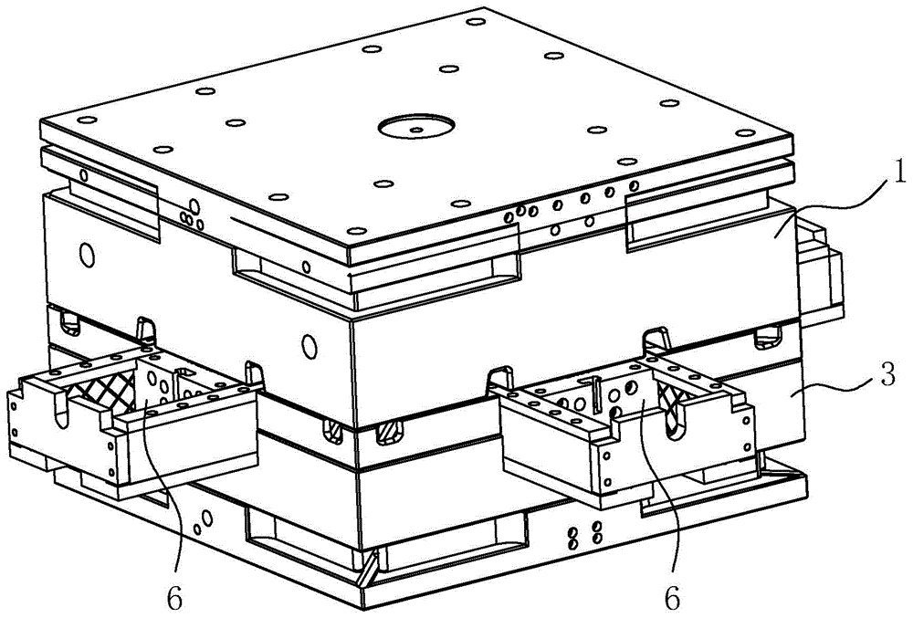
图2为实施例的结构图;2 is a structural diagram of an embodiment;
图3为实施例上模的结构图;Fig. 3 is the structural diagram of the upper die of the embodiment;
图4为实施例上侧滑模块的结构图;4 is a structural diagram of a side-sliding module on the embodiment;
图5为实施例下模的结构图;Fig. 5 is the structural diagram of the lower die of the embodiment;
图6为实施例下侧滑模块的结构图;6 is a structural diagram of a side sliding module under an embodiment;
图7为实施例侧抽型芯的第一结构图;7 is a first structural diagram of the side-pulling core of the embodiment;
图8为实施例侧抽型芯的第二结构图;8 is a second structural diagram of the side-pulling core of the embodiment;
图9为实施例侧抽型芯在合模情况下局部剖视图。FIG. 9 is a partial cross-sectional view of the side-pulling core of the embodiment when the mold is closed.
附图标记:1、上模;11、上型芯;12、上斜导块;2、上侧滑模块;21、第三模腔;3、下模;31、下型芯;32、下斜导块;4、下侧滑模块;41、第一模腔;42、第二模腔;5、侧抽块;51、侧抽型芯;52、弹块;53、弧形面;54、活动空腔;55、侧抽斜导块;6、第四模腔;71、井体;72、主承接管;73、支管;74、导角面。Reference numerals: 1. Upper mold; 11. Upper core; 12. Upper inclined guide block; 2. Upper side sliding module; 21. Third cavity; 3. Lower mold; 31. Lower core; Oblique guide block; 4. Lower side slide module; 41, First cavity; 42, Second cavity; 5, Side draw block; 51, Side draw core; 52, Elastic block; 53, Arc surface; 54 , movable cavity; 55, side pulling guide block; 6, fourth mold cavity; 71, well body; 72, main bearing pipe; 73, branch pipe; 74, chamfer surface.
具体实施方式Detailed ways
以下结合附图对本发明作进一步详细说明。The present invention will be further described in detail below with reference to the accompanying drawings.
一种便于脱模的检查井模具,本实施例注塑加工的检查井如图1所示,检查井包括井体71、主承接管72、支管73,主承接管72主要用于连接主进水管,支管73用于侧向的排水。支管73的数量可以为一个,也可以为四个,支管73可以分布在井体71的不同侧面,在支管73和主承接管72内壁的连接处,设置有导角面74,便于疏通管道不易磨损检查井。An inspection well mold for easy demoulding. The inspection well for injection molding in this embodiment is shown in Figure 1. The inspection well includes a
如图2至图6所示所示,检查井模具包括可相互合拢或者分离的上模1和下模3,上模1块相对于下模3的一侧设置有四块上侧滑模块2,下模3相对于上模1的一侧设置有四块下侧滑模块4,上侧滑模块2和下侧滑模块4位置一一对应。As shown in FIG. 2 to FIG. 6 , the inspection well mold includes an upper mold 1 and a
如图3至图4所示,上模1上设置有上型芯11,四个上测模块均环绕在上型芯11四周,同时,上侧滑模块2上还设置有用于形成支管73下半部分的第三模腔21。上侧滑模块2可相对上模1往下进行外扩的倾斜运动,上模1上设置有供上侧滑模块2滑动的上斜导块12,上斜导块12的截面均为T字形,每个上侧滑模块2上设置的上斜导块12数量为两个。上侧滑模块2通过油缸驱动其往外侧向滑动。As shown in FIG. 3 to FIG. 4 , the upper mold 1 is provided with an
如图5至图6所示,下模3上设置有下型芯31,四个下侧滑模块4环绕下型芯31周向分布。下侧滑模块4可相对下模3往上进行外扩的倾斜运动,下侧滑模块4上设置有用于成型主承接管72的第一模腔41、用于成型支管73上半部分的第二模腔42,下模3上设置有供下侧滑模块4滑动的下斜导块32,下斜导块32的截面为T字形,每个下侧滑模块4上设置的下斜导块32数量为两个,下侧滑模块4通过油缸驱动其往外侧向滑动。As shown in FIG. 5 to FIG. 6 , the
如图1、图7所示,下模3上还设置有用于侧抽的侧抽块5,侧抽块5的数量为四个,且分布在下模3的四个边上,侧抽块5通过油缸驱动其稳定滑动。每个侧抽块5上设置有侧抽型芯51,侧抽型芯51与侧抽块5为可拆卸连接,如果该侧抽块5位置不需要注塑支管73,只需要将侧抽型芯51更换即可。侧抽块5可以驱动侧抽型芯51插入到第二模腔42和第三膜腔内。As shown in Figures 1 and 7, the
上侧滑模块2与下侧滑模块4上均设置有用于成型检查井井体71的第四模腔6。当合模时,即四个上侧滑模块2和下侧滑模块4合拢时,上型芯11和下型芯31可插入第二模腔42内和第四模腔6内,侧抽型芯51可插入第二模腔42和第三膜腔内,上型芯11、下型芯31、第一模腔41和第四模腔6之间的间隙形成用于成型检查井井体71和主承接管72的空间,侧抽型芯51、第二模腔42和第三模腔21之间的间隙形成用于成型检查井支管73的空间。The upper
其中,如图7至图9所示,在每个侧抽型芯51远离侧抽块5的侧面上设置有可倾斜往下运动的弹块52,弹块52外壁上设置有用于形成检查井支管73内壁导角面74的的弧形面53,侧抽型芯51内设置有容纳弹块52的活动空腔54,活动空腔54内设置有驱动弹块52位移的弹性件和用于引导弹块52滑动的侧抽斜导块55,侧抽斜导块55上设置有T字形的槽,供弹块52滑动。在本实施例中,弹性件为弹簧。Among them, as shown in FIGS. 7 to 9 , on the side of each side-pulling
以上所述仅是本发明的示范性实施方式,而非用于限制本发明的保护范围,本发明的保护范围由所附的权利要求确定。The above descriptions are only exemplary embodiments of the present invention, and are not intended to limit the protection scope of the present invention, which is determined by the appended claims.
Claims (8)
Priority Applications (1)
| Application Number | Priority Date | Filing Date | Title |
|---|---|---|---|
| CN202010798012.9A CN112060482B (en) | 2020-08-10 | 2020-08-10 | Inspection well mold for easy demoulding |
Applications Claiming Priority (1)
| Application Number | Priority Date | Filing Date | Title |
|---|---|---|---|
| CN202010798012.9A CN112060482B (en) | 2020-08-10 | 2020-08-10 | Inspection well mold for easy demoulding |
Publications (2)
| Publication Number | Publication Date |
|---|---|
| CN112060482A true CN112060482A (en) | 2020-12-11 |
| CN112060482B CN112060482B (en) | 2024-11-01 |
Family
ID=73661044
Family Applications (1)
| Application Number | Title | Priority Date | Filing Date |
|---|---|---|---|
| CN202010798012.9A Active CN112060482B (en) | 2020-08-10 | 2020-08-10 | Inspection well mold for easy demoulding |
Country Status (1)
| Country | Link |
|---|---|
| CN (1) | CN112060482B (en) |
Citations (7)
| Publication number | Priority date | Publication date | Assignee | Title |
|---|---|---|---|---|
| KR100879278B1 (en) * | 2008-05-30 | 2009-01-16 | 이정재 | Injection Mold for Core Replacement |
| CN204076698U (en) * | 2014-07-31 | 2015-01-07 | 上海维科精密模塑有限公司 | A kind of injection mold side slide pulled core structure |
| CN204736375U (en) * | 2015-05-21 | 2015-11-04 | 陈明强 | Plastic check well's combination formula forming die |
| CN204997872U (en) * | 2015-08-18 | 2016-01-27 | 陈明强 | Branch pipe forming mechanism of plastic check well assembling die |
| CN204997882U (en) * | 2015-08-18 | 2016-01-27 | 陈明强 | Slider mechanism of plastic check well assembling die |
| CN204997883U (en) * | 2015-08-18 | 2016-01-27 | 陈明强 | Plastic check well's assembling die |
| CN212312630U (en) * | 2020-08-10 | 2021-01-08 | 山东文远环保科技股份有限公司 | Inspection well mould convenient to drawing of patterns |
-
2020
- 2020-08-10 CN CN202010798012.9A patent/CN112060482B/en active Active
Patent Citations (7)
| Publication number | Priority date | Publication date | Assignee | Title |
|---|---|---|---|---|
| KR100879278B1 (en) * | 2008-05-30 | 2009-01-16 | 이정재 | Injection Mold for Core Replacement |
| CN204076698U (en) * | 2014-07-31 | 2015-01-07 | 上海维科精密模塑有限公司 | A kind of injection mold side slide pulled core structure |
| CN204736375U (en) * | 2015-05-21 | 2015-11-04 | 陈明强 | Plastic check well's combination formula forming die |
| CN204997872U (en) * | 2015-08-18 | 2016-01-27 | 陈明强 | Branch pipe forming mechanism of plastic check well assembling die |
| CN204997882U (en) * | 2015-08-18 | 2016-01-27 | 陈明强 | Slider mechanism of plastic check well assembling die |
| CN204997883U (en) * | 2015-08-18 | 2016-01-27 | 陈明强 | Plastic check well's assembling die |
| CN212312630U (en) * | 2020-08-10 | 2021-01-08 | 山东文远环保科技股份有限公司 | Inspection well mould convenient to drawing of patterns |
Also Published As
| Publication number | Publication date |
|---|---|
| CN112060482B (en) | 2024-11-01 |
Similar Documents
| Publication | Publication Date | Title |
|---|---|---|
| CN103753779B (en) | Sewage pipeline inspection well mold release mechanism | |
| CN207535236U (en) | A kind of rubber corrugated lid pickoff | |
| CN104260291B (en) | Compact inspection shaft well seat demoulding mechanism | |
| CN102241119A (en) | Core pulling mechanism for flaring pipe fitting injection mold | |
| CN212219136U (en) | Inspection well mould | |
| CN119058026B (en) | Forming die for rubber sealing piece processing | |
| CN112060482B (en) | Inspection well mold for easy demoulding | |
| CN212312630U (en) | Inspection well mould convenient to drawing of patterns | |
| CN110524814A (en) | A kind of slim slide block core pulling moulding/demoulding structure and its release method | |
| CN106956401A (en) | A kind of plastic cement direction indicators cover injection mold and its release method | |
| CN204054519U (en) | Multipurpose plastic drainage inspection well adjustable mould | |
| CN202878606U (en) | Mould for base of inspection well | |
| CN212736899U (en) | Injection mold for producing inspection well | |
| CN214725796U (en) | Mechanical automatic core pulling mechanism | |
| CN106426776B (en) | A kind of injection mold of plastic elbow | |
| CN212288468U (en) | Arc return bend injection mold | |
| CN210999814U (en) | Plastic shell mold of automobile air filter element device | |
| JP2012121157A (en) | Molding apparatus and molding method | |
| CN212147408U (en) | Injection mold of V type thin wall injection molding | |
| CN112060481B (en) | Injection molds for the production of inspection wells | |
| CN116118125A (en) | Core-pulling structure mold for composite bent pipe | |
| CN209920453U (en) | Plastic water channel assembly injection mold | |
| CN108115895B (en) | Vertical multi-cavity 90-degree bending die with elastic block molding inclined sliding core pulling function | |
| CN208730278U (en) | A kind of secondary stripper apparatus of duplex injection mould for insert | |
| CN220447037U (en) | Forming die for engine oil pan of automobile engine |
Legal Events
| Date | Code | Title | Description |
|---|---|---|---|
| PB01 | Publication | ||
| PB01 | Publication | ||
| SE01 | Entry into force of request for substantive examination | ||
| SE01 | Entry into force of request for substantive examination | ||
| GR01 | Patent grant | ||
| GR01 | Patent grant | ||
| PE01 | Entry into force of the registration of the contract for pledge of patent right | ||
| PE01 | Entry into force of the registration of the contract for pledge of patent right |
Denomination of invention: convenient to demold check manhole mold Granted publication date: 20241101 Pledgee: Shandong Linzi Rural Commercial Bank Co.,Ltd. Pledgor: SHANDONG WENYUAN ENVIRONMENTAL TECHNOLOGY CO.,LTD. Registration number: Y2025980052974 |