CN112038168A - High-voltage vacuum switch tube with double arc-extinguishing chambers - Google Patents
High-voltage vacuum switch tube with double arc-extinguishing chambers Download PDFInfo
- Publication number
- CN112038168A CN112038168A CN202010981980.3A CN202010981980A CN112038168A CN 112038168 A CN112038168 A CN 112038168A CN 202010981980 A CN202010981980 A CN 202010981980A CN 112038168 A CN112038168 A CN 112038168A
- Authority
- CN
- China
- Prior art keywords
- fixedly connected
- static
- movable
- chamber
- rod
- Prior art date
- Legal status (The legal status is an assumption and is not a legal conclusion. Google has not performed a legal analysis and makes no representation as to the accuracy of the status listed.)
- Granted
Links
Images

Classifications
-
- H—ELECTRICITY
- H01—ELECTRIC ELEMENTS
- H01H—ELECTRIC SWITCHES; RELAYS; SELECTORS; EMERGENCY PROTECTIVE DEVICES
- H01H33/00—High-tension or heavy-current switches with arc-extinguishing or arc-preventing means
- H01H33/60—Switches wherein the means for extinguishing or preventing the arc do not include separate means for obtaining or increasing flow of arc-extinguishing fluid
- H01H33/66—Vacuum switches
- H01H33/664—Contacts; Arc-extinguishing means, e.g. arcing rings
-
- H—ELECTRICITY
- H01—ELECTRIC ELEMENTS
- H01H—ELECTRIC SWITCHES; RELAYS; SELECTORS; EMERGENCY PROTECTIVE DEVICES
- H01H33/00—High-tension or heavy-current switches with arc-extinguishing or arc-preventing means
- H01H33/60—Switches wherein the means for extinguishing or preventing the arc do not include separate means for obtaining or increasing flow of arc-extinguishing fluid
- H01H33/66—Vacuum switches
- H01H33/666—Operating arrangements
Landscapes
- Arc-Extinguishing Devices That Are Switches (AREA)
- High-Tension Arc-Extinguishing Switches Without Spraying Means (AREA)
Abstract
本发明公开了一种双灭弧室高压真空开关管,涉及高压灭弧技术领域。本发明包括绝缘壳体,绝缘壳体的一端并排设有两灭弧室,绝缘壳体另一端设有一容置室,灭弧室内固定连接一静导电杆,两静导电杆一端延长至绝缘壳体同一端的外部,静导电杆的另一端设有静触头;容置室内设有一用于连接两静导电杆的动连接块,动连接块上设有一对与静导电杆一一对应的动导电杆,动导电杆一端延长至灭弧室内部,且动导电杆的一端设有与静触头配合连接的动触头;动连接块上固定连接一推杆,推杆表面上固定连接有波纹管。本发明通过将波纹管设在在容置室内,容置室与灭弧室隔离,从而保护了波纹管不被电弧击穿。
The invention discloses a high-voltage vacuum switch tube with double arc extinguishing chambers, and relates to the technical field of high-voltage arc extinguishing. The invention includes an insulating shell, one end of the insulating shell is provided with two arc extinguishing chambers side by side, the other end of the insulating shell is provided with a accommodating chamber, the arc extinguishing chamber is fixedly connected with a static conducting rod, and one end of the two static conducting rods is extended to the insulating shell Outside the same end of the body, the other end of the static conductive rod is provided with a static contact; the accommodating chamber is provided with a dynamic connecting block for connecting two static conductive rods, and a pair of dynamic connecting blocks corresponding to the static conductive rods are arranged on the dynamic connecting block. Conductive rod, one end of the movable conductive rod is extended to the inside of the arc extinguishing chamber, and one end of the movable conductive rod is provided with a movable contact which is matched and connected with the static contact; a push rod is fixedly connected to the movable connection block, and a push rod is fixedly connected on the surface of the push rod Bellows. In the present invention, the bellows is arranged in the accommodating chamber, and the accommodating chamber is isolated from the arc extinguishing chamber, thereby protecting the bellows from being broken down by electric arcs.
Description
技术领域technical field
本发明属于高压灭弧技术领域,特别是涉及一种双灭弧室高压真空开关管。The invention belongs to the technical field of high-voltage arc extinguishing, in particular to a high-voltage vacuum switch tube with double arc extinguishing chambers.
背景技术Background technique
真空开关是自动测控系统内的压力,利用压力传感器原理,内置高精度传感器设计的一款防止系统内的压力过高或过低,输出开关信号,确保设备在无人看管下精确稳定的运行的控制器,真空开关是一种用于真空系统的压力保护自动控制器,当系统中的真空压力大于设定点,则控制器会自动切断电路,发出信号,以保证系统的正常工作。Vacuum switch is the pressure in the automatic measurement and control system. It uses the principle of pressure sensor and built-in high-precision sensor to prevent the pressure in the system from being too high or too low, and outputs the switch signal to ensure accurate and stable operation of the equipment under unattended operation Controller, vacuum switch is a pressure protection automatic controller for vacuum system. When the vacuum pressure in the system is greater than the set point, the controller will automatically cut off the circuit and send a signal to ensure the normal operation of the system.
现有真空开关管主要由真空绝缘壳体、动导电杆、静导电杆、波纹管、上下盖板组成,由于波纹管与动导电杆、静导电杆在同一灭弧室,静导电杆与动导电杆接触瞬间产生电弧,而波纹管管壁均薄,常出现波纹管被被击穿的现象。The existing vacuum switch tube is mainly composed of a vacuum insulating shell, a movable conductive rod, a static conductive rod, a bellows, and an upper and lower cover plate. When the conductive rod contacts, an arc is generated instantly, and the wall of the bellows is thin, and the bellows is often broken down.
发明内容SUMMARY OF THE INVENTION
本发明目的在于提供一种双灭弧室高压真空开关管,通过在绝缘壳体内设有双灭弧室,波纹管设在容置室内与灭弧室隔离,解决了现有波纹管易被击穿的问题。The purpose of the present invention is to provide a high-voltage vacuum switch tube with double arc extinguishing chambers. By arranging double arc extinguishing chambers in the insulating shell, the bellows is arranged in the accommodating chamber and isolated from the arc extinguishing chamber, which solves the problem that the existing bellows is easy to be hit. wear problem.
为解决上述技术问题,本发明是通过以下技术方案实现的:In order to solve the above-mentioned technical problems, the present invention is achieved through the following technical solutions:
本发明为一种双灭弧室高压真空开关管,包括绝缘壳体,所述绝缘壳体的一端并排设有两灭弧室,所述绝缘壳体另一端设有一容置室,所述灭弧室与所述容置室均为真空密封状态,所述灭弧室内设有用于保护绝缘壳体的防护系统;所述灭弧室内固定连接一静导电杆,两所述静导电杆一端延长至所述绝缘壳体同一端的外部,且所述静导电杆与所述绝缘壳体之间固定连接有上端盖板,所述静导电杆的另一端设有静触头;所述容置室内设有一用于连接两所述静导电杆的动连接块,所述动连接块为导体材料,所述动连接块上设有一对与所述静导电杆一一对应的动导电杆,所述动导电杆一端延长至所述灭弧室内部,且所述动导电杆的一端设有与所述静触头配合连接的动触头;所述动连接块上固定连接一推杆,所述推杆一端延长至所述绝缘壳体外部,所述推杆与所述绝缘壳体之间固定连接有下端盖板,所述推杆表面上固定连接有波纹管,所述波纹管的上下两端分别与所述推杆、下端盖板之间均密封连接,所述上端盖板与所述下端盖板上均设有通孔。The present invention relates to a high-voltage vacuum switch tube with double arc extinguishing chambers, comprising an insulating shell, one end of the insulating shell is provided with two arc extinguishing chambers side by side, and the other end of the insulating shell is provided with an accommodating chamber, Both the arc chamber and the accommodating chamber are in a vacuum-sealed state, the arc extinguishing chamber is provided with a protection system for protecting the insulating shell; a static conducting rod is fixedly connected to the arc extinguishing chamber, and one end of the two static conducting rods is extended to the outside of the same end of the insulating housing, and an upper end cover plate is fixedly connected between the static conducting rod and the insulating housing, and the other end of the static conducting rod is provided with a static contact; There is a dynamic connecting block for connecting the two static conductive rods. The dynamic connecting block is made of conductor material. One end of the movable conductive rod is extended to the inside of the arc extinguishing chamber, and one end of the movable conductive rod is provided with a movable contact which is matched and connected with the static contact; a push rod is fixedly connected to the movable connection block, and the One end of the push rod is extended to the outside of the insulating shell, a lower end cover is fixedly connected between the push rod and the insulating shell, a corrugated pipe is fixedly connected on the surface of the push rod, and the upper and lower parts of the corrugated pipe are fixedly connected. The ends are sealed and connected with the push rod and the lower end cover plate respectively, and the upper end cover plate and the lower end cover plate are both provided with through holes.
进一步地,所述防护系统包括一包围所述动触头和静触头的环形屏蔽罩,所述屏蔽罩上方固定连接有上防护罩,所述屏蔽罩下方固定连接有下防护罩。Further, the protection system includes an annular shielding cover surrounding the movable contact and the stationary contact, an upper protective cover is fixedly connected above the shielding cover, and a lower protective cover is fixedly connected below the shielding cover.
进一步地,所述屏蔽罩、上防护罩、下防护罩均通过法兰固定连接在所述绝缘壳体的内壁。Further, the shielding cover, the upper protective cover, and the lower protective cover are all fixedly connected to the inner wall of the insulating housing through flanges.
进一步地,所述动连接块与所述容置室内壁固定连接一弹性件。Further, the movable connecting block is fixedly connected with an elastic member to the inner wall of the accommodating chamber.
进一步地,所述弹性件为一弹簧。Further, the elastic member is a spring.
进一步地,所述动导电杆与灭弧室之间固定连接有导向套。Further, a guide sleeve is fixedly connected between the movable conductive rod and the arc extinguishing chamber.
本发明具有以下有益效果:The present invention has the following beneficial effects:
1、本发明通过在绝缘壳体内设有双灭弧室,灭弧室内设有防护系统,灭弧室内连接有静导电杆,容置室内连接有动连接块,通过外部驱动结构推动推杆,使动连接块将两个静导电杆连通,从而实现了电路的导通。1. In the present invention, double arc extinguishing chambers are arranged in the insulating shell, a protection system is arranged in the arc extinguishing chamber, a static conducting rod is connected in the arc extinguishing chamber, a moving connecting block is connected in the accommodating chamber, and the push rod is pushed through the external driving structure, The moving connecting block connects the two static conductive rods, thereby realizing the conduction of the circuit.
2、本发明通过将波纹管设在在容置室内,容置室与灭弧室之间隔离,且通过防护系统的防护作用,从而保护了波纹管不被电弧击穿,延长了真空开关管的使用寿命,且弹性件使动导电杆与静导电杆之间连接紧密,使得电流流通顺畅。2. The present invention protects the bellows from arc breakdown by arranging the bellows in the accommodating chamber, isolating the accommodating chamber from the arc-extinguishing chamber, and protecting the bellows from arc breakdown and prolonging the vacuum switch tube. The service life is long, and the elastic member makes the connection between the moving conductive rod and the static conductive rod tightly, so that the current flows smoothly.
当然,实施本发明的任一产品并不一定需要同时达到以上所述的所有优点。Of course, it is not necessary for any product embodying the present invention to achieve all of the above-described advantages simultaneously.
附图说明Description of drawings
为了更清楚地说明本发明实施例的技术方案,下面将对实施例描述所需要使用的附图作简单地介绍,显而易见地,下面描述中的附图仅仅是本发明的一些实施例,对于本领域普通技术人员来讲,在不付出创造性劳动的前提下,还可以根据这些附图获得其他的附图。In order to illustrate the technical solutions of the embodiments of the present invention more clearly, the following briefly introduces the accompanying drawings used in the description of the embodiments. Obviously, the drawings in the following description are only some embodiments of the present invention. For those of ordinary skill in the art, other drawings can also be obtained from these drawings without any creative effort.
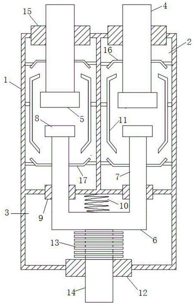
图1为本发明的结构示意图;Fig. 1 is the structural representation of the present invention;
附图中,各标号所代表的部件列表如下:In the accompanying drawings, the list of components represented by each number is as follows:
1-绝缘壳体,2-灭弧室,3-容置室,4-静导电杆,5-静触头,6-动连接块,7-动导电杆,8-动触头,9-导向套,10-弹性件,11-屏蔽罩,12-下端盖板,13-波纹管,14-推杆,15-上端盖板,16-上防护罩,17-下防护罩。1-Insulation shell, 2-Arc extinguishing chamber, 3-Accommodating chamber, 4-Static conductive rod, 5-Static contact, 6-Moving connecting block, 7-Moving conductive rod, 8-Moving contact, 9- Guide sleeve, 10-elastic part, 11-shield, 12-lower cover, 13-bellows, 14-push rod, 15-upper cover, 16-upper protective cover, 17-lower protective cover.
具体实施方式Detailed ways
下面将结合本发明实施例中的附图,对本发明实施例中的技术方案进行清楚、完整地描述,显然,所描述的实施例仅仅是本发明一部分实施例,而不是全部的实施例。基于本发明中的实施例,本领域普通技术人员在没有作出创造性劳动前提下所获得的所有其它实施例,都属于本发明保护的范围。The technical solutions in the embodiments of the present invention will be clearly and completely described below with reference to the accompanying drawings in the embodiments of the present invention. Obviously, the described embodiments are only a part of the embodiments of the present invention, but not all of the embodiments. Based on the embodiments of the present invention, all other embodiments obtained by those of ordinary skill in the art without creative efforts shall fall within the protection scope of the present invention.
在本发明的描述中,需要理解的是,术语“上端”、“通孔”、“下”、“厚度”、“顶”、“中”、“长度”、“内”、“内壁”等指示方位或位置关系,仅是为了便于描述本发明和简化描述,而不是指示或暗示所指的组件或元件必须具有特定的方位,以特定的方位构造和操作,因此不能理解为对本发明的限制。In the description of the present invention, it should be understood that the terms "upper end", "through hole", "lower", "thickness", "top", "middle", "length", "inner", "inner wall", etc. Indicates the orientation or positional relationship, only for the convenience of describing the present invention and simplifying the description, rather than indicating or implying that the components or elements referred to must have a specific orientation, are constructed and operated in a specific orientation, and therefore should not be construed as a limitation of the present invention .
请参阅图1所示,本发明为一种双灭弧室高压真空开关管,包括绝缘壳体1,绝缘壳体1为陶瓷材质,绝缘壳体1的一端并排设有两灭弧室2,两个灭弧室2之间相互独立,绝缘壳体1另一端设有一容置室3,容置室3与灭弧室2之间相互独立,灭弧室2与容置室3均为真空密封状态;灭弧室2内设有用于保护绝缘壳体1的防护系统,灭弧室2内固定连接一静导电杆4,两静导电杆4一端延长至绝缘壳体1同一端的外部,且静导电杆4与绝缘壳体1之间固定连接有上端盖板15,静导电杆4的另一端设有静触头5;容置室3内设有一用于连接两静导电杆4的动连接块6,动连接块6为铜制材料,动连接块6上设有一对与静导电杆4一一对应的动导电杆7,动导电杆7一端延长至灭弧室2内部,且动导电杆7的延长至灭弧室2内的一端设有与静触头5配合连接的动触头8,静触头5与动触头8均为圆盘状结构,动连接块6上固定连接一推杆14,推杆14为绝缘体材料,推杆14一端延长至绝缘壳体1外部,且推杆14与外部的驱动机构连接,推杆14与绝缘壳体1之间固定连接有下端盖板12,推杆14表面上固定连接有波纹管13,波纹管13与推杆14、下端盖板12之间均密封连接,上端盖板15与下端盖板12上均设有通孔。Referring to FIG. 1, the present invention is a high-voltage vacuum switch tube with dual arc extinguishing chambers, comprising an insulating casing 1, the insulating casing 1 is made of ceramic material, and one end of the insulating casing 1 is provided with two arc extinguishing chambers 2 side by side, The two arc extinguishing chambers 2 are independent of each other, and the other end of the insulating shell 1 is provided with an
优选的,防护系统包括一包围动触头8和静触头5的环形屏蔽罩11,对绝缘壳体1的内壁进行保护,屏蔽罩11上方固定连接有上防护罩16,屏蔽罩11下方固定连接有下防护罩17,上防护罩11和下防护罩17分别对绝缘课题1的上下端进行保护。Preferably, the protection system includes an annular shielding cover 11 surrounding the movable contact 8 and the static contact 5 to protect the inner wall of the insulating housing 1 , an upper
优选的,屏蔽罩11、上防护罩16、下防护罩17均通过法兰固定连接在绝缘壳体1的内壁,且上防护罩16、下防护罩17上均设有通孔。Preferably, the shielding cover 11 , the upper
优选的,为使静触头5与动触头8之间连接紧密,动连接块6与容置室3内壁固定连接一弹性件10。Preferably, in order to make the connection between the static contact 5 and the movable contact 8 tight, the movable connection block 6 is fixedly connected to the inner wall of the
优选的,弹性件10为一弹簧,弹簧处于拉伸状态。Preferably, the
优选的,动导电杆7与灭弧室2之间固定连接有导向套9。Preferably, a
本实施例的一个具体应用为:发明在绝缘壳体1内设有双灭弧室2,灭弧室2内连接有静导电杆4,容置室3内连接有动导电杆7,通过外部驱动结构推动推杆14,使动连接块6将两个静导电杆4连通,从而实现了电路的导通,波纹管13设在在容置室3内,容置室3与灭弧室2隔离,从而保护了波纹管13不被电弧击穿。A specific application of this embodiment is as follows: the invention is provided with dual arc extinguishing chambers 2 in the insulating housing 1 , the arc extinguishing chamber 2 is connected with a static conductive rod 4 , and the
在本说明书的描述中,参考术语“一个实施例”、“示例”、“具体示例”等的描述意指结合该实施例或示例描述的具体特征、结构、材料或者特点包含于本发明的至少一个实施例或示例中。在本说明书中,对上述术语的示意性表述不一定指的是相同的实施例或示例。而且,描述的具体特征、结构、材料或者特点可以在任何的一个或多个实施例或示例中以合适的方式结合。In the description of this specification, description with reference to the terms "one embodiment," "example," "specific example," etc. means that a particular feature, structure, material, or characteristic described in connection with the embodiment or example is included in at least one aspect of the present invention. in one embodiment or example. In this specification, schematic representations of the above terms do not necessarily refer to the same embodiment or example. Furthermore, the particular features, structures, materials or characteristics described may be combined in any suitable manner in any one or more embodiments or examples.
以上公开的本发明优选实施例只是用于帮助阐述本发明。优选实施例并没有详尽叙述所有的细节,也不限制该发明仅为所述的具体实施方式。显然,根据本说明书的内容,可作很多的修改和变化。本说明书选取并具体描述这些实施例,是为了更好地解释本发明的原理和实际应用,从而使所属技术领域技术人员能很好地理解和利用本发明。本发明仅受权利要求书及其全部范围和等效物的限制。The above-disclosed preferred embodiments of the present invention are provided only to help illustrate the present invention. The preferred embodiments do not exhaust all the details, nor do they limit the invention to only the described embodiments. Obviously, many modifications and variations are possible in light of the content of this specification. The present specification selects and specifically describes these embodiments in order to better explain the principles and practical applications of the present invention, so that those skilled in the art can well understand and utilize the present invention. The present invention is to be limited only by the claims and their full scope and equivalents.
Claims (6)
Priority Applications (1)
| Application Number | Priority Date | Filing Date | Title |
|---|---|---|---|
| CN202010981980.3A CN112038168B (en) | 2020-09-17 | 2020-09-17 | High-voltage vacuum switch tube with double arc-extinguishing chambers |
Applications Claiming Priority (1)
| Application Number | Priority Date | Filing Date | Title |
|---|---|---|---|
| CN202010981980.3A CN112038168B (en) | 2020-09-17 | 2020-09-17 | High-voltage vacuum switch tube with double arc-extinguishing chambers |
Publications (2)
| Publication Number | Publication Date |
|---|---|
| CN112038168A true CN112038168A (en) | 2020-12-04 |
| CN112038168B CN112038168B (en) | 2022-11-08 |
Family
ID=73590284
Family Applications (1)
| Application Number | Title | Priority Date | Filing Date |
|---|---|---|---|
| CN202010981980.3A Active CN112038168B (en) | 2020-09-17 | 2020-09-17 | High-voltage vacuum switch tube with double arc-extinguishing chambers |
Country Status (1)
| Country | Link |
|---|---|
| CN (1) | CN112038168B (en) |
Citations (8)
| Publication number | Priority date | Publication date | Assignee | Title |
|---|---|---|---|---|
| WO2013000309A1 (en) * | 2011-06-30 | 2013-01-03 | 西安交通大学 | High-voltage single-fracture vacuum interrupter |
| CN202839450U (en) * | 2012-09-28 | 2013-03-27 | 王永法 | Vacuum arc extinguishing chamber |
| CN103050324A (en) * | 2012-12-17 | 2013-04-17 | 大连理工大学 | Vacuum circuit breaker based on T-shaped double-break vacuum interrupter |
| CN104576176A (en) * | 2014-12-22 | 2015-04-29 | 苏州施源特电气有限公司 | Circuit breaker of arc extinguish chambers in series connection |
| CN204303660U (en) * | 2014-12-22 | 2015-04-29 | 苏州施源特电气有限公司 | A kind of single arc-chutes double-fracture breaker |
| US20170287661A1 (en) * | 2014-11-12 | 2017-10-05 | Shenyang Huade High Technology Electric Co., Ltd. | Three-position vacuum switch for realizing external grounding of load side by using bridge switch |
| CN206849755U (en) * | 2017-06-19 | 2018-01-05 | 国网江苏省电力公司盐城供电公司 | The primary cut-out of synchronization double-action contact |
| CN109326484A (en) * | 2018-11-28 | 2019-02-12 | 河南中医药大学 | A vacuum interrupter with adjustable vacuum degree |
-
2020
- 2020-09-17 CN CN202010981980.3A patent/CN112038168B/en active Active
Patent Citations (8)
| Publication number | Priority date | Publication date | Assignee | Title |
|---|---|---|---|---|
| WO2013000309A1 (en) * | 2011-06-30 | 2013-01-03 | 西安交通大学 | High-voltage single-fracture vacuum interrupter |
| CN202839450U (en) * | 2012-09-28 | 2013-03-27 | 王永法 | Vacuum arc extinguishing chamber |
| CN103050324A (en) * | 2012-12-17 | 2013-04-17 | 大连理工大学 | Vacuum circuit breaker based on T-shaped double-break vacuum interrupter |
| US20170287661A1 (en) * | 2014-11-12 | 2017-10-05 | Shenyang Huade High Technology Electric Co., Ltd. | Three-position vacuum switch for realizing external grounding of load side by using bridge switch |
| CN104576176A (en) * | 2014-12-22 | 2015-04-29 | 苏州施源特电气有限公司 | Circuit breaker of arc extinguish chambers in series connection |
| CN204303660U (en) * | 2014-12-22 | 2015-04-29 | 苏州施源特电气有限公司 | A kind of single arc-chutes double-fracture breaker |
| CN206849755U (en) * | 2017-06-19 | 2018-01-05 | 国网江苏省电力公司盐城供电公司 | The primary cut-out of synchronization double-action contact |
| CN109326484A (en) * | 2018-11-28 | 2019-02-12 | 河南中医药大学 | A vacuum interrupter with adjustable vacuum degree |
Also Published As
| Publication number | Publication date |
|---|---|
| CN112038168B (en) | 2022-11-08 |
Similar Documents
| Publication | Publication Date | Title |
|---|---|---|
| US2480622A (en) | Electric switch | |
| US8575509B2 (en) | Vacuum switching apparatus including first and second movable contact assemblies, and vacuum electrical switching apparatus including the same | |
| WO2017206653A1 (en) | Relay | |
| CA2790731A1 (en) | Retainer, vacuum interrupter, and electrical switching apparatus including the same | |
| JP5060328B2 (en) | Vacuum switchgear | |
| JPS58165221A (en) | Disconnecting switch | |
| KR102458208B1 (en) | Insulation media for electrical energy transmission devices | |
| GB966110A (en) | Circuit interrupter | |
| EP1121739A1 (en) | Gas-insulated switching device | |
| CN207852570U (en) | A dual power supply type UHV vacuum interrupter | |
| CN101233593A (en) | Electrical switching device and method of operating an electrical switching device | |
| CN103198970A (en) | Vacuum envelope with double-fracture structure | |
| US4491704A (en) | Vacuum circuit interrupter having vacuum monitoring apparatus | |
| CN216671493U (en) | A vacuum circuit breaker for electrical engineering | |
| CN112038168B (en) | High-voltage vacuum switch tube with double arc-extinguishing chambers | |
| CN113517155B (en) | A vacuum isolation arc extinguishing device | |
| US4847456A (en) | Vacuum circuit interrupter with axial magnetic arc transfer mechanism | |
| CN206976233U (en) | A kind of circuit breaker for inflating cabinet | |
| CN101436487A (en) | Vacuum arc-extinguishing chamber | |
| TWI795246B (en) | Vacuum arc-extinguishing chamber and vacuum circuit breaker with a triggered cathode | |
| CN209822545U (en) | Outdoor solid-sealed vacuum circuit breaker | |
| CN214590159U (en) | Pole-mounted combined electrical apparatus | |
| JP4011050B2 (en) | Vacuum switchgear | |
| CN101194330A (en) | Electric switch with annular static contact | |
| CN207381850U (en) | A kind of on-pole switch equipment built in disconnecting switch |
Legal Events
| Date | Code | Title | Description |
|---|---|---|---|
| PB01 | Publication | ||
| PB01 | Publication | ||
| SE01 | Entry into force of request for substantive examination | ||
| SE01 | Entry into force of request for substantive examination | ||
| GR01 | Patent grant | ||
| GR01 | Patent grant | ||
| TR01 | Transfer of patent right |
Effective date of registration: 20260305 Address after: 210000 No. 6, pan Neng Road, hi tech Development Zone, Jiangsu, Nanjing Patentee after: NNAJING PANENG TECHNOLOGY DEVELOPMENT Co.,Ltd. Country or region after: China Address before: 230000 East, 1st floor, building 11, electromechanical Industrial Park, 767 Yulan Avenue, hi tech Zone, Hefei City, Anhui Province Patentee before: Anhui Puzhong electromechanical Co.,Ltd. Country or region before: China |
|
| TR01 | Transfer of patent right |