CN112031982A - Hydraulic generator with stable output voltage and frequency - Google Patents
Hydraulic generator with stable output voltage and frequency Download PDFInfo
- Publication number
- CN112031982A CN112031982A CN202010845404.6A CN202010845404A CN112031982A CN 112031982 A CN112031982 A CN 112031982A CN 202010845404 A CN202010845404 A CN 202010845404A CN 112031982 A CN112031982 A CN 112031982A
- Authority
- CN
- China
- Prior art keywords
- hydraulic generator
- output voltage
- oil
- stable output
- cavity
- Prior art date
- Legal status (The legal status is an assumption and is not a legal conclusion. Google has not performed a legal analysis and makes no representation as to the accuracy of the status listed.)
- Granted
Links
Images


Classifications
-
- F—MECHANICAL ENGINEERING; LIGHTING; HEATING; WEAPONS; BLASTING
- F03—MACHINES OR ENGINES FOR LIQUIDS; WIND, SPRING, OR WEIGHT MOTORS; PRODUCING MECHANICAL POWER OR A REACTIVE PROPULSIVE THRUST, NOT OTHERWISE PROVIDED FOR
- F03B—MACHINES OR ENGINES FOR LIQUIDS
- F03B13/00—Adaptations of machines or engines for special use; Combinations of machines or engines with driving or driven apparatus; Power stations or aggregates
-
- F—MECHANICAL ENGINEERING; LIGHTING; HEATING; WEAPONS; BLASTING
- F03—MACHINES OR ENGINES FOR LIQUIDS; WIND, SPRING, OR WEIGHT MOTORS; PRODUCING MECHANICAL POWER OR A REACTIVE PROPULSIVE THRUST, NOT OTHERWISE PROVIDED FOR
- F03B—MACHINES OR ENGINES FOR LIQUIDS
- F03B11/00—Parts or details not provided for in, or of interest apart from, the preceding groups, e.g. wear-protection couplings, between turbine and generator
- F03B11/004—Valve arrangements
-
- F—MECHANICAL ENGINEERING; LIGHTING; HEATING; WEAPONS; BLASTING
- F03—MACHINES OR ENGINES FOR LIQUIDS; WIND, SPRING, OR WEIGHT MOTORS; PRODUCING MECHANICAL POWER OR A REACTIVE PROPULSIVE THRUST, NOT OTHERWISE PROVIDED FOR
- F03B—MACHINES OR ENGINES FOR LIQUIDS
- F03B15/00—Controlling
- F03B15/02—Controlling by varying liquid flow
- F03B15/04—Controlling by varying liquid flow of turbines
- F03B15/06—Regulating, i.e. acting automatically
- F03B15/08—Regulating, i.e. acting automatically by speed, e.g. by measuring electric frequency or liquid flow
- F03B15/12—Regulating, i.e. acting automatically by speed, e.g. by measuring electric frequency or liquid flow with retroactive action
-
- F—MECHANICAL ENGINEERING; LIGHTING; HEATING; WEAPONS; BLASTING
- F03—MACHINES OR ENGINES FOR LIQUIDS; WIND, SPRING, OR WEIGHT MOTORS; PRODUCING MECHANICAL POWER OR A REACTIVE PROPULSIVE THRUST, NOT OTHERWISE PROVIDED FOR
- F03B—MACHINES OR ENGINES FOR LIQUIDS
- F03B15/00—Controlling
- F03B15/02—Controlling by varying liquid flow
- F03B15/04—Controlling by varying liquid flow of turbines
- F03B15/06—Regulating, i.e. acting automatically
- F03B15/16—Regulating, i.e. acting automatically by power output
-
- H—ELECTRICITY
- H02—GENERATION; CONVERSION OR DISTRIBUTION OF ELECTRIC POWER
- H02J—ELECTRIC POWER NETWORKS; CIRCUIT ARRANGEMENTS OR SYSTEMS FOR SUPPLYING OR DISTRIBUTING ELECTRIC POWER; SYSTEMS FOR STORING ELECTRIC ENERGY
- H02J7/00—Circuit arrangements for charging or discharging batteries or for supplying loads from batteries
- H02J7/14—Circuit arrangements for charging or discharging batteries or for supplying loads from batteries for charging batteries from dynamo-electric generators driven at varying speed, e.g. on vehicle
-
- H—ELECTRICITY
- H02—GENERATION; CONVERSION OR DISTRIBUTION OF ELECTRIC POWER
- H02K—DYNAMO-ELECTRIC MACHINES
- H02K5/00—Casings; Enclosures; Supports
- H02K5/24—Casings; Enclosures; Supports specially adapted for suppression or reduction of noise or vibrations
-
- H—ELECTRICITY
- H02—GENERATION; CONVERSION OR DISTRIBUTION OF ELECTRIC POWER
- H02K—DYNAMO-ELECTRIC MACHINES
- H02K9/00—Arrangements for cooling or ventilating
- H02K9/19—Arrangements for cooling or ventilating for machines with closed casing and closed-circuit cooling using a liquid cooling medium, e.g. oil
- H02K9/193—Arrangements for cooling or ventilating for machines with closed casing and closed-circuit cooling using a liquid cooling medium, e.g. oil with provision for replenishing the cooling medium; with means for preventing leakage of the cooling medium
-
- Y—GENERAL TAGGING OF NEW TECHNOLOGICAL DEVELOPMENTS; GENERAL TAGGING OF CROSS-SECTIONAL TECHNOLOGIES SPANNING OVER SEVERAL SECTIONS OF THE IPC; TECHNICAL SUBJECTS COVERED BY FORMER USPC CROSS-REFERENCE ART COLLECTIONS [XRACs] AND DIGESTS
- Y02—TECHNOLOGIES OR APPLICATIONS FOR MITIGATION OR ADAPTATION AGAINST CLIMATE CHANGE
- Y02E—REDUCTION OF GREENHOUSE GAS [GHG] EMISSIONS, RELATED TO ENERGY GENERATION, TRANSMISSION OR DISTRIBUTION
- Y02E10/00—Energy generation through renewable energy sources
- Y02E10/20—Hydro energy
Landscapes
- Engineering & Computer Science (AREA)
- Chemical & Material Sciences (AREA)
- Combustion & Propulsion (AREA)
- Mechanical Engineering (AREA)
- General Engineering & Computer Science (AREA)
- Power Engineering (AREA)
- Connection Of Motors, Electrical Generators, Mechanical Devices, And The Like (AREA)
- Control Of Eletrric Generators (AREA)
Abstract
本发明提供一种输出电压频率稳定的液压发电机,包括液压发电机本体,所述液压发电机本体包括底板和智能系统,所述智能系统包括电压监测器、温度传感器、控制箱、智能处理器、控制开关、控油装置、控制阀、蓄流器、变流器、叠加模块、转化器、供电装置、水泵、排风扇和制冷装置,所述底板上安装有箱体,所述箱体的底部焊接有固定板,该输出电压频率稳定的液压发电机通过控油装置与电压监测器相连接,对电机内部定子的旋转速度进行控制,从而通过控制阀控制油管的工作数量,工作数量不同,转速不同对输出电压的电流不同,根据不同情况下进行自行快速调整,使用便捷。
The invention provides a hydraulic generator with stable output voltage and frequency, including a hydraulic generator body, the hydraulic generator body including a base plate and an intelligent system, and the intelligent system includes a voltage monitor, a temperature sensor, a control box, and an intelligent processor , control switch, oil control device, control valve, accumulator, converter, stacking module, converter, power supply device, water pump, exhaust fan and refrigeration device, a box body is installed on the bottom plate, and the bottom of the box body is welded There is a fixed plate, the hydraulic generator with stable output voltage and frequency is connected with the voltage monitor through the oil control device to control the rotation speed of the stator inside the motor, so as to control the working quantity of the oil pipe through the control valve. The current of the output voltage is different, and it can be adjusted quickly by itself according to different situations, which is convenient to use.
Description
技术领域technical field
本发明涉及液压发电机设备领域,更具体地,涉及一种输出电压频率稳定的液压发电机。The invention relates to the field of hydraulic generator equipment, and more particularly, to a hydraulic generator with stable output voltage and frequency.
背景技术Background technique
发电机指将其他形式的能源转换成电能的机械设备,为了满足能源需求,需要使用发电机完成发电进行使用,现有的发电机大多数为柴油发电机,柴油发电机体积及重量增较大,增加能源消耗,另一方面,柴油发电机利用柴油进行发电,增加使用成本的同时污染环境,现有的发电机在使用时,无法提供稳定电压频率进行使用,造成无法正常工作,另外,电压的不稳定易造成设备的损害,现有的液压发动机的输出频率高于柴油的电压频率,但是现有的液压发电机无法根据不同的电压输入情况,自行调整输出电压的稳定性,无法满足不同情况下的不同使用,功能单一。A generator refers to a mechanical device that converts other forms of energy into electrical energy. In order to meet the energy demand, a generator needs to be used to generate electricity. Most of the existing generators are diesel generators, and the volume and weight of diesel generators increase greatly. , increase energy consumption. On the other hand, diesel generators use diesel to generate electricity, which increases the cost of use and pollutes the environment. When the existing generator is in use, it cannot provide stable voltage and frequency for use, resulting in failure to work normally. In addition, the voltage The instability can easily cause equipment damage. The output frequency of the existing hydraulic engine is higher than the voltage frequency of the diesel engine, but the existing hydraulic generator cannot adjust the stability of the output voltage by itself according to different voltage input conditions, and cannot meet the requirements of different voltages. Different uses in different situations, single function.
申请号为201120006299.3的专利说明书中公开了一种适用于智能变电站通信的宽带电力载波系统及组网方法,本申请包括发动机、液压油泵、液压马达、发电机,还包括一个控制芯片,与控制芯片相连的信号采集模块、以及与PLC控制芯片连接的电磁阀,电磁阀的动作端与液压油泵连接,信号采集模块采集发电机的电压信号的频率信号。本实用新型由于将发电机的电压和频率信号作为反馈信号,利用电磁阀输出控制液压油泵的工作状态,可以控制发电机的输出精度和稳定度,并且实用新型设置了频率转换开关,发电机的输出频率可以在两个频率之间切换。然而,该专利无法实现用的同时能够通过内部的控油装置和蓄流器对内部输出的电压进行控制,从而保证输出电压的稳定性。The patent specification with the application number of 201120006299.3 discloses a broadband power carrier system suitable for intelligent substation communication and a networking method. This application includes an engine, a hydraulic oil pump, a hydraulic motor, a generator, and a control chip. The connected signal collection module and the solenoid valve connected with the PLC control chip, the action end of the solenoid valve is connected with the hydraulic oil pump, and the signal collection module collects the frequency signal of the voltage signal of the generator. Because the utility model uses the voltage and frequency signals of the generator as feedback signals, and uses the output of the solenoid valve to control the working state of the hydraulic oil pump, the output precision and stability of the generator can be controlled, and the utility model is provided with a frequency conversion switch. The output frequency can be switched between two frequencies. However, this patent cannot be used, and at the same time, the internal output voltage can be controlled through the internal oil control device and the accumulator, thereby ensuring the stability of the output voltage.
发明内容SUMMARY OF THE INVENTION
本发明提供一种输出电压频率稳定的液压发电机,该装置结构新颖,使用的同时能够通过内部的控油装置和蓄流器对内部输出的电压进行控制,从而保证输出电压的稳定性。The invention provides a hydraulic generator with stable output voltage and frequency. The device has a novel structure and can control the internal output voltage through an internal oil control device and an accumulator while in use, thereby ensuring the stability of the output voltage.
为了达到上述技术效果,本发明的技术方案如下:In order to achieve above-mentioned technical effect, technical scheme of the present invention is as follows:
一种输出电压频率稳定的液压发电机,包括液压发电机本体,所述液压发电机本体包括底板和智能系统,所述智能系统包括电压监测器、温度传感器、控制箱、智能处理器、控制开关、控油装置、控制阀、蓄流器、变流器、叠加模块、转化器、供电装置、水泵、排风扇和制冷装置,所述底板上安装有箱体,所述箱体的底部焊接有固定板,所述固定板通过固定螺栓固定在底板上,所述箱体的底部安装有水箱,所述水箱上安装有注水管,所述箱体的一侧开有开口,所述开口的内部安装有支撑管,所述控油装置安装在支撑管的一端,所述控油装置上安装有油管,所述支撑管的一端安装有电机,所述电机通过安装座安装在底板上,所述蓄流器安装在电机的一端,所述电机通过输出轴与蓄流器相连接。A hydraulic generator with stable output voltage and frequency, comprising a hydraulic generator body, the hydraulic generator body including a base plate and an intelligent system, the intelligent system including a voltage monitor, a temperature sensor, a control box, an intelligent processor, and a control switch , oil control device, control valve, accumulator, converter, stacking module, converter, power supply device, water pump, exhaust fan and refrigeration device, a box body is installed on the bottom plate, and a fixed plate is welded on the bottom of the box body , the fixing plate is fixed on the bottom plate by fixing bolts, a water tank is installed at the bottom of the box body, a water injection pipe is installed on the water tank, an opening is opened on one side of the box body, and a water tank is installed inside the opening. A support pipe, the oil control device is installed at one end of the support pipe, an oil pipe is installed on the oil control device, a motor is installed at one end of the support pipe, the motor is installed on the bottom plate through a mounting seat, and the accumulator is installed At one end of the motor, the motor is connected to the accumulator through the output shaft.
进一步地,所述控油装置的内部设置有空腔,所述空腔的内部安装有涡轮,所述涡轮上安装有转动杆,所述转动杆上安装有定子,所述定子安装在电机的内部,所述控油装置的内部设置有管道,所述管道与油管相连接。Further, a cavity is provided inside the oil control device, a turbine is installed inside the cavity, a rotating rod is installed on the turbine, a stator is installed on the rotating rod, and the stator is installed inside the motor , the inside of the oil control device is provided with a pipeline, and the pipeline is connected with the oil pipe.
优选地,所述油管的数量为4个,所述油管包括2个进油管和2个排油管,所述控制箱上安装有箱盖。Preferably, the number of the oil pipes is 4, the oil pipes include 2 oil inlet pipes and 2 oil discharge pipes, and a box cover is installed on the control box.
进一步地,所述箱体的内部设置有存放腔,所述存放腔通过水管与水箱相连接,所述存放腔与箱体之间设置有安装槽,所述排风扇安装在安装槽的内部,所述箱体上设置有散热口,所述散热口与排风扇相配合。Further, the inside of the box body is provided with a storage cavity, the storage cavity is connected with the water tank through a water pipe, an installation slot is arranged between the storage cavity and the box body, and the exhaust fan is installed inside the installation slot, so The box body is provided with a heat dissipation port, and the heat dissipation port is matched with the exhaust fan.
进一步地,所述箱体的内部设置有固定腔,所述固定腔与电机相配合,所述电机与固定腔之间设置有缓冲垫。Further, a fixing cavity is arranged inside the box body, the fixing cavity is matched with the motor, and a buffer pad is arranged between the motor and the fixing cavity.
进一步地,所述水箱的内部设置有第一空腔,所述第一空腔与水箱之间设置有风管,所述水泵安装在第一空腔的内部,所述水泵与风管相配合,所述制冷装置安装在水箱的内壁上。Further, a first cavity is arranged inside the water tank, an air duct is arranged between the first cavity and the water tank, the water pump is installed inside the first cavity, and the water pump cooperates with the air duct , the refrigeration device is installed on the inner wall of the water tank.
进一步地,所述蓄流器包括变流器、叠加模块和转化器,所述蓄流器通过电线与变流器、叠加模块和转化器相连接。Further, the accumulator includes a converter, a stacking module and a converter, and the current accumulator is connected with the converter, the stacking module and the converter through wires.
作为本发明的一种优选实施方式,所述电压监测器安装在蓄流器的内部,所述温度传感器安装在控制箱的内部。As a preferred embodiment of the present invention, the voltage monitor is installed inside the accumulator, and the temperature sensor is installed inside the control box.
进一步地,所述控制箱包括智能处理器和控制开关,所述控制开关通过电线与智能处理器相连接。Further, the control box includes an intelligent processor and a control switch, and the control switch is connected with the intelligent processor through a wire.
进一步地,所述供电装置通过电线与水泵、排风扇和制冷装置相连接。Further, the power supply device is connected with the water pump, the exhaust fan and the refrigeration device through electric wires.
与现有技术相比,本发明技术方案的有益效果是:Compared with the prior art, the beneficial effects of the technical solution of the present invention are:
1、该输出电压频率稳定的液压发电机通过控油装置与电压监测器相连接,对电机内部定子的旋转速度进行控制,从而通过控制阀控制油管的工作数量,工作数量不同,转速不同对输出电压的电流不同,根据不同情况下进行自行快速调整,使用便捷;1. The hydraulic generator with stable output voltage and frequency is connected to the voltage monitor through the oil control device to control the rotation speed of the internal stator of the motor, so as to control the number of oil pipes through the control valve. The current is different, and it can be quickly adjusted according to different situations, which is convenient to use;
2、该输出电压频率稳定的液压发电机内部的电机通过将液压产生的势能转化为电能进入到蓄流器的内部,通过蓄流器可对输出和输入的电压进行控制,从而保证电压的稳定性,当电压达不到输出要求时,通过内部的叠加模块对电流进行存放并叠加,当叠加到输出要求后排出,从而保证输出电压的稳定性,功能多样;2. The motor inside the hydraulic generator with stable output voltage and frequency enters into the accumulator by converting the potential energy generated by the hydraulic pressure into electric energy, and the output and input voltage can be controlled by the accumulator to ensure the stability of the voltage. When the voltage does not meet the output requirements, the current is stored and superimposed through the internal superposition module. When the superposition reaches the output requirements, it is discharged to ensure the stability of the output voltage and has various functions;
3、该输出电压频率稳定的液压发电机通过在箱体的内部设置的存放腔和水箱相配合存放水,通过水完全包裹电机,存放腔内部的水对电机的温度快速吸附和对噪音的吸附,通过内部的温度传感器,对内部温度进行监测,通过温度传感器将温度传输到智能处理器上进行分析处理,通过制冷装置对水制冷从而保证内部温度的正常使用,使用便捷。3. The hydraulic generator with stable output voltage and frequency stores water through the storage cavity and the water tank set inside the box. The water completely wraps the motor, and the water in the storage cavity quickly absorbs the temperature of the motor and the noise. , The internal temperature is monitored by the internal temperature sensor, the temperature is transmitted to the intelligent processor for analysis and processing through the temperature sensor, and the water is cooled by the refrigeration device to ensure the normal use of the internal temperature, which is convenient to use.
附图说明Description of drawings
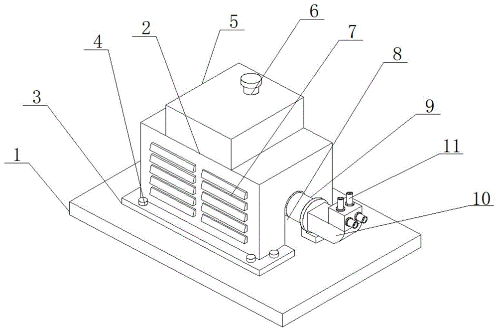
图1为本发明一种输出电压频率稳定的液压发电机的结构示意图;1 is a schematic structural diagram of a hydraulic generator with stable output voltage and frequency of the present invention;
图2为本发明一种输出电压频率稳定的液压发电机的电机与蓄流器的结构示意图;2 is a schematic structural diagram of a motor and an accumulator of a hydraulic generator with stable output voltage and frequency of the present invention;
图3为本发明一种输出电压频率稳定的液压发电机的控油装置的剖面结构示意图;3 is a schematic cross-sectional structural diagram of an oil control device for a hydraulic generator with stable output voltage and frequency of the present invention;
图4为本发明一种输出电压频率稳定的液压发电机的箱体与水箱的剖面结构示意图;4 is a schematic cross-sectional structural diagram of a box body and a water tank of a hydraulic generator with stable output voltage and frequency of the present invention;
图5为本发明一种输出电压频率稳定的液压发电机的智能系统的结构示意图;5 is a schematic structural diagram of an intelligent system of a hydraulic generator with stable output voltage and frequency of the present invention;
图中:1、底板;2、箱体;3、固定板;4、固定螺栓;5、水箱;6、注水管;7、散热口;8、开口;9、支撑管;10、控油装置;11、油管;13、安装座;14、控制箱;15、箱盖;16、电机;17、蓄流器;18、管道;19、空腔;20、涡轮;21、安装槽;22、排风扇;23、存放腔;24、水泵;25、制冷装置;26、风管;27、固定腔;28、温度传感器;29、电压监测器;30、智能处理器;31、控制开关;32、控制阀;33、变流器;34、叠加模块;35、转化器;36、供电装置。In the figure: 1. Bottom plate; 2. Box body; 3. Fixing plate; 4. Fixing bolts; 5. Water tank; 6. Water injection pipe; 7. Heat dissipation port; 8. Opening; 9. Support pipe; 11. Oil pipe; 13. Mounting seat; 14. Control box; 15. Box cover; 16. Motor; 17. Accumulator; 18. Pipe; 19. Cavity; 20. Turbine; 21. Installation slot; 22. Exhaust fan ; 23, storage cavity; 24, water pump; 25, refrigeration device; 26, air duct; 27, fixed cavity; 28, temperature sensor; 29, voltage monitor; 30, intelligent processor; 31, control switch; 32, control valve; 33, converter; 34, stacking module; 35, converter; 36, power supply device.
具体实施方式Detailed ways
附图仅用于示例性说明,不能理解为对本专利的限制;The accompanying drawings are for illustrative purposes only, and should not be construed as limitations on this patent;
为了更好说明本实施例,附图某些部件会有省略、放大或缩小,并不代表实际产品的尺寸;In order to better illustrate this embodiment, some parts of the drawings are omitted, enlarged or reduced, which do not represent the size of the actual product;
对于本领域技术人员来说,附图中某些公知结构及其说明可能省略是可以理解的。It will be understood by those skilled in the art that some well-known structures and their descriptions may be omitted from the drawings.
如图1至图5所示,一种输出电压频率稳定的液压发电机,包括液压发电机本体,所述液压发电机本体包括底板1和智能系统,所述智能系统包括电压监测器29、温度传感器28、控制箱14、智能处理器30、控制开关31、控油装置10、控制阀32、蓄流器17、变流器33、叠加模块34、转化器35、供电装置36、水泵24、排风扇22和制冷装置25,所述底板1上安装有箱体2,所述箱体2的底部焊接有固定板3,所述固定板3通过固定螺栓4固定在底板1上,所述箱体2的底部安装有水箱5,所述水箱5上安装有注水管6,所述箱体2的一侧开有开口8,所述开口8的内部安装有支撑管9,所述控油装置10安装在支撑管9的一端,所述控油装置10上安装有油管11,所述支撑管9的一端安装有电机16,所述电机16通过安装座13安装在底板1上,所述蓄流器17安装在电机16的一端,所述电机16通过输出轴与蓄流器17相连接。As shown in FIG. 1 to FIG. 5, a hydraulic generator with stable output voltage and frequency includes a hydraulic generator body, the hydraulic generator body includes a base plate 1 and an intelligent system, the intelligent system includes a voltage monitor 29, a temperature Sensor 28, control box 14, intelligent processor 30, control switch 31, oil control device 10, control valve 32, accumulator 17, inverter 33, stacking module 34, converter 35, power supply device 36, water pump 24, exhaust fan 22 and refrigerating device 25, a box body 2 is installed on the bottom plate 1, a fixing plate 3 is welded to the bottom of the box body 2, and the fixing plate 3 is fixed on the bottom plate 1 by fixing bolts 4, and the box body 2 A water tank 5 is installed on the bottom of the water tank 5, a water injection pipe 6 is installed on the water tank 5, an opening 8 is opened on one side of the tank body 2, and a support pipe 9 is installed inside the opening 8, and the oil control device 10 is installed in the One end of the support pipe 9, the oil control device 10 is mounted with an oil pipe 11, one end of the support pipe 9 is mounted with a motor 16, the motor 16 is mounted on the bottom plate 1 through the mounting seat 13, and the accumulator 17 is mounted At one end of the electric motor 16, the electric motor 16 is connected to the accumulator 17 through the output shaft.
作为本发明的一种优选实施方式,所述控油装置10的内部设置有空腔19,所述空腔19的内部安装有涡轮20,所述涡轮20上安装有转动杆,所述转动杆上安装有定子,所述定子安装在电机16的内部,所述控油装置10的内部设置有管道18,所述管道18与油管11相连接。As a preferred embodiment of the present invention, a
作为本发明的一种优选实施方式,所述油管11的数量为4个,所述油管11包括2个进油管和2个排油管,所述控制箱14上安装有箱盖15。As a preferred embodiment of the present invention, the number of the
作为本发明的一种优选实施方式,所述箱体2的内部设置有存放腔23,所述存放腔23通过水管与水箱5相连接,所述存放腔23与箱体2之间设置有安装槽21,所述排风扇22安装在安装槽21的内部,所述箱体2上设置有散热口7,所述散热口7与排风扇22相配合。As a preferred embodiment of the present invention, a
作为本发明的一种优选实施方式,所述箱体2的内部设置有固定腔27,所述固定腔27与电机16相配合,所述电机16与固定腔27之间设置有缓冲垫。As a preferred embodiment of the present invention, a fixing
作为本发明的一种优选实施方式,所述水箱5的内部设置有空腔一,所述空腔一与水箱5之间设置有风管26,所述水泵24安装在空腔一的内部,所述水泵24与风管26相配合,所述制冷装置25安装在水箱5的内壁上。As a preferred embodiment of the present invention, a
作为本发明的一种优选实施方式,所述蓄流器17包括变流器33、叠加模块34和转化器35,所述蓄流器17通过电线与变流器33、叠加模块34和转化器35相连接。As a preferred embodiment of the present invention, the
作为本发明的一种优选实施方式,所述电压监测器29安装在蓄流器17的内部,所述温度传感器28安装在控制箱14的内部。As a preferred embodiment of the present invention, the voltage monitor 29 is installed inside the
作为本发明的一种优选实施方式,所述控制箱14包括智能处理器30和控制开关31,所述控制开关31通过电线与智能处理器30相连接。As a preferred embodiment of the present invention, the
作为本发明的一种优选实施方式,所述供电装置36通过电线与水泵24、排风扇22和制冷装置25相连接。As a preferred embodiment of the present invention, the
当使用该装置时,通过外接液压泵通过连接管与油管11相连接,通过液压泵提供高速的液压油来满足本装置的工作需求,当需要工作时,通过油管11进入液压油,液压油高速流动对涡轮20进行冲击,冲击的同时使涡轮20进行旋转,另一侧的油管11产生吸力,为涡轮20的旋转提供助力,涡轮20旋转后,带动涡轮20上的转动杆进行旋转,转动杆上设置有的定子在电机内部进行高速旋转,定子的旋转速度不同时产生的电压不同,通过电压检测器29对电压进行监测,当电压达不到使用要求时,通过控油装置10控制油管11的工作数量,通过内部的控制阀32完成控制,油管11的分别安装在管道18上,通过数量的不同加大液压油的冲击力,使涡轮20带动转动杆的转速不同,从而对产生的电压进行调节使用便捷,内部的电机16通过将液压产生的势能转化为电能进入到蓄流器17的内部,通过蓄流器17可对输出和输入的电压进行控制,从而保证电压的稳定性,当电压达不到输出要求时,通过内部的叠加模块34对电流进行存放并叠加,当叠加到输出要求后排出,从而保证输出电压的稳定性,通过在箱体2的内部设置的存放腔23和水箱5相配合存放水,通过水完全包裹电机16,存放腔23内部的水对电机16的温度快速吸附和对噪音的吸附,通过内部的温度传感器28,对内部温度进行监测,通过温度传感器28将温度传输到智能处理器30上进行分析处理,通过控制开关31控制制冷装置25对水制冷从而保证内部温度的正常使用,使用便捷,存放腔23和水箱5之间存有交流管道,可实现内部的水的流通。When the device is used, the external hydraulic pump is connected to the
相同或相似的标号对应相同或相似的部件;The same or similar reference numbers correspond to the same or similar parts;
附图中描述位置关系的用于仅用于示例性说明,不能理解为对本专利的限制;The positional relationship described in the accompanying drawings is only for exemplary illustration, and should not be construed as a limitation on this patent;
显然,本发明的上述实施例仅仅是为清楚地说明本发明所作的举例,而并非是对本发明的实施方式的限定。对于所属领域的普通技术人员来说,在上述说明的基础上还可以做出其它不同形式的变化或变动。这里无需也无法对所有的实施方式予以穷举。凡在本发明的精神和原则之内所作的任何修改、等同替换和改进等,均应包含在本发明权利要求的保护范围之内。Obviously, the above-mentioned embodiments of the present invention are only examples for clearly illustrating the present invention, and are not intended to limit the embodiments of the present invention. For those of ordinary skill in the art, changes or modifications in other different forms can also be made on the basis of the above description. There is no need and cannot be exhaustive of all implementations here. Any modification, equivalent replacement and improvement made within the spirit and principle of the present invention shall be included within the protection scope of the claims of the present invention.
Claims (10)
Priority Applications (1)
| Application Number | Priority Date | Filing Date | Title |
|---|---|---|---|
| CN202010845404.6A CN112031982B (en) | 2020-08-20 | 2020-08-20 | Hydraulic generator with stable output voltage and frequency |
Applications Claiming Priority (1)
| Application Number | Priority Date | Filing Date | Title |
|---|---|---|---|
| CN202010845404.6A CN112031982B (en) | 2020-08-20 | 2020-08-20 | Hydraulic generator with stable output voltage and frequency |
Publications (2)
| Publication Number | Publication Date |
|---|---|
| CN112031982A true CN112031982A (en) | 2020-12-04 |
| CN112031982B CN112031982B (en) | 2022-03-29 |
Family
ID=73581683
Family Applications (1)
| Application Number | Title | Priority Date | Filing Date |
|---|---|---|---|
| CN202010845404.6A Active CN112031982B (en) | 2020-08-20 | 2020-08-20 | Hydraulic generator with stable output voltage and frequency |
Country Status (1)
| Country | Link |
|---|---|
| CN (1) | CN112031982B (en) |
Cited By (1)
| Publication number | Priority date | Publication date | Assignee | Title |
|---|---|---|---|---|
| CN113904500A (en) * | 2021-09-03 | 2022-01-07 | 广州智光节能有限公司 | Motor assembly |
Citations (8)
| Publication number | Priority date | Publication date | Assignee | Title |
|---|---|---|---|---|
| US5977648A (en) * | 1996-10-21 | 1999-11-02 | Sundstrand Corporation | Hydraulically driven low reactance, large air gap permanent magnet generator and voltage regulation system for use therewith |
| CN2427929Y (en) * | 1999-11-10 | 2001-04-25 | 赵克 | Water power driver electricity generator used for ship |
| CN1502806A (en) * | 2002-11-22 | 2004-06-09 | 谢森生 | Hydrolic mechanism free electric motor servo system water turbine speed regulator |
| CN2934640Y (en) * | 2006-07-13 | 2007-08-15 | 武汉市汉诺优电控有限责任公司 | High oil pressure paddle turbine governor |
| CN101046188A (en) * | 2007-04-19 | 2007-10-03 | 鞠延忠 | Tidal power generator |
| CN101315055A (en) * | 2007-06-01 | 2008-12-03 | 何振中 | Ocean energy conversion method |
| CN201937532U (en) * | 2011-01-11 | 2011-08-17 | 廊坊开发区新赛浦石油设备有限公司 | Hydraulic generator control system |
| CN202250343U (en) * | 2011-09-09 | 2012-05-30 | 潍柴动力股份有限公司 | A three-stage speed regulation hydraulic drive cooling system |
-
2020
- 2020-08-20 CN CN202010845404.6A patent/CN112031982B/en active Active
Patent Citations (8)
| Publication number | Priority date | Publication date | Assignee | Title |
|---|---|---|---|---|
| US5977648A (en) * | 1996-10-21 | 1999-11-02 | Sundstrand Corporation | Hydraulically driven low reactance, large air gap permanent magnet generator and voltage regulation system for use therewith |
| CN2427929Y (en) * | 1999-11-10 | 2001-04-25 | 赵克 | Water power driver electricity generator used for ship |
| CN1502806A (en) * | 2002-11-22 | 2004-06-09 | 谢森生 | Hydrolic mechanism free electric motor servo system water turbine speed regulator |
| CN2934640Y (en) * | 2006-07-13 | 2007-08-15 | 武汉市汉诺优电控有限责任公司 | High oil pressure paddle turbine governor |
| CN101046188A (en) * | 2007-04-19 | 2007-10-03 | 鞠延忠 | Tidal power generator |
| CN101315055A (en) * | 2007-06-01 | 2008-12-03 | 何振中 | Ocean energy conversion method |
| CN201937532U (en) * | 2011-01-11 | 2011-08-17 | 廊坊开发区新赛浦石油设备有限公司 | Hydraulic generator control system |
| CN202250343U (en) * | 2011-09-09 | 2012-05-30 | 潍柴动力股份有限公司 | A three-stage speed regulation hydraulic drive cooling system |
Cited By (2)
| Publication number | Priority date | Publication date | Assignee | Title |
|---|---|---|---|---|
| CN113904500A (en) * | 2021-09-03 | 2022-01-07 | 广州智光节能有限公司 | Motor assembly |
| CN113904500B (en) * | 2021-09-03 | 2024-02-02 | 广州智光节能有限公司 | Motor assembly |
Also Published As
| Publication number | Publication date |
|---|---|
| CN112031982B (en) | 2022-03-29 |
Similar Documents
| Publication | Publication Date | Title |
|---|---|---|
| CN114228899B (en) | Air supply system and method suitable for ultra-large air layer drag reduction ships | |
| CN103887927B (en) | A kind of energy storage device of magnetic suspension flywheel cooling system | |
| CN107725274B (en) | Air energy storage power generation system based on wind power kinetic energy | |
| CN113794332B (en) | Integrated electric drive system | |
| CN113982833B (en) | A wind power generation system | |
| CN112031982B (en) | Hydraulic generator with stable output voltage and frequency | |
| CN104728052B (en) | Dual planetary gear mechanical couplings formula compressed-air energy-storage system and method for work | |
| RU2714894C1 (en) | Direct-current electric generator of turbine driven by compressed air | |
| CN216981722U (en) | Heat dissipation structure of air-air cooling double-fed wind driven generator | |
| CN216762064U (en) | Gas supply system suitable for ultra-large type gas layer drag reduction ship | |
| CN115306492A (en) | A high-speed coaxial steam turbine generator set | |
| CN205013330U (en) | Direct -cooled thermal power plant is with external rotor permanent magnetism fan system | |
| CN211058958U (en) | Heat dissipation device for engine room cover of wind turbine generator | |
| CN209681458U (en) | Electric welding machine with air-exhausting duct | |
| CN211880256U (en) | Explosion-proof buffer structure of three-phase asynchronous motor | |
| CN106762773A (en) | Electric automobile oil-free scroll air compressor machine gas is stopped the PMSM drive control devices of pump | |
| CN117293985A (en) | Power generation equipment consisting of paddle-free turbine and disc type axial motor | |
| CN115580069A (en) | A generator frequency conversion cooling system and its intelligent control method | |
| CN220185319U (en) | Separable vacuum interconnection device | |
| CN110953065A (en) | Generating set with unit volume and ultrahigh power | |
| CN206770258U (en) | The PMSM drive control devices of electric automobile oil-free scroll air compressor machine gas brake pump | |
| CN206908451U (en) | New no shaft core accumulated energy flywheel | |
| CN223359419U (en) | Domestic intelligent constant-pressure variable-frequency pump | |
| CN221652362U (en) | Cooling device for hydroelectric power generation equipment | |
| CN205975818U (en) | Intelligent speed control does not have negative pressure water supply equipment and water supply system |
Legal Events
| Date | Code | Title | Description |
|---|---|---|---|
| PB01 | Publication | ||
| PB01 | Publication | ||
| SE01 | Entry into force of request for substantive examination | ||
| SE01 | Entry into force of request for substantive examination | ||
| GR01 | Patent grant | ||
| GR01 | Patent grant |