CN112009837A - Material loading conveyor and automatic labeling production line - Google Patents
Material loading conveyor and automatic labeling production line Download PDFInfo
- Publication number
- CN112009837A CN112009837A CN202011054753.2A CN202011054753A CN112009837A CN 112009837 A CN112009837 A CN 112009837A CN 202011054753 A CN202011054753 A CN 202011054753A CN 112009837 A CN112009837 A CN 112009837A
- Authority
- CN
- China
- Prior art keywords
- label
- station
- feeding
- group
- drives
- Prior art date
- Legal status (The legal status is an assumption and is not a legal conclusion. Google has not performed a legal analysis and makes no representation as to the accuracy of the status listed.)
- Granted
Links
Images



Classifications
-
- B—PERFORMING OPERATIONS; TRANSPORTING
- B65—CONVEYING; PACKING; STORING; HANDLING THIN OR FILAMENTARY MATERIAL
- B65C—LABELLING OR TAGGING MACHINES, APPARATUS, OR PROCESSES
- B65C9/00—Details of labelling machines or apparatus
- B65C9/02—Devices for moving articles, e.g. containers, past labelling station
- B65C9/04—Devices for moving articles, e.g. containers, past labelling station having means for rotating the articles
-
- B—PERFORMING OPERATIONS; TRANSPORTING
- B65—CONVEYING; PACKING; STORING; HANDLING THIN OR FILAMENTARY MATERIAL
- B65C—LABELLING OR TAGGING MACHINES, APPARATUS, OR PROCESSES
- B65C9/00—Details of labelling machines or apparatus
- B65C9/06—Devices for presenting articles in predetermined attitude or position at labelling station
-
- B—PERFORMING OPERATIONS; TRANSPORTING
- B65—CONVEYING; PACKING; STORING; HANDLING THIN OR FILAMENTARY MATERIAL
- B65C—LABELLING OR TAGGING MACHINES, APPARATUS, OR PROCESSES
- B65C9/00—Details of labelling machines or apparatus
- B65C9/08—Label feeding
-
- B—PERFORMING OPERATIONS; TRANSPORTING
- B65—CONVEYING; PACKING; STORING; HANDLING THIN OR FILAMENTARY MATERIAL
- B65C—LABELLING OR TAGGING MACHINES, APPARATUS, OR PROCESSES
- B65C9/00—Details of labelling machines or apparatus
- B65C9/26—Devices for applying labels
-
- B—PERFORMING OPERATIONS; TRANSPORTING
- B65—CONVEYING; PACKING; STORING; HANDLING THIN OR FILAMENTARY MATERIAL
- B65C—LABELLING OR TAGGING MACHINES, APPARATUS, OR PROCESSES
- B65C9/00—Details of labelling machines or apparatus
- B65C9/40—Controls; Safety devices
-
- B—PERFORMING OPERATIONS; TRANSPORTING
- B65—CONVEYING; PACKING; STORING; HANDLING THIN OR FILAMENTARY MATERIAL
- B65C—LABELLING OR TAGGING MACHINES, APPARATUS, OR PROCESSES
- B65C9/00—Details of labelling machines or apparatus
- B65C9/46—Applying date marks, code marks, or the like, to the label during labelling
Landscapes
- Specific Conveyance Elements (AREA)
- Labeling Devices (AREA)
Abstract
Description
技术领域technical field
本发明涉及物料输送与贴标,尤其涉及一种可选择在贴标前是否翻转物料的上料输送装置及贴标生产线。The invention relates to material conveying and labeling, in particular to a feeding conveying device and a labeling production line that can select whether to turn over materials before labeling.
背景技术Background technique
现有的固态硬盘动贴标工序中,依据工艺要求,需要对有的内存条正面贴标,对有的内存条背面贴标,而现有的自动贴标生产线只能应对一种贴标工序,适应性小。In the existing SSD dynamic labeling process, according to the process requirements, it is necessary to label the front of some memory modules and the back of some memory modules, and the existing automatic labeling production line can only cope with one labeling process. , the adaptability is small.
而且,由于生产线中的地方极为有限,很难设计出可对内存条正反面进行贴标的生产线。Moreover, because of the extremely limited space in the production line, it is difficult to design a production line that can label the front and back of the memory stick.
故,急需一种可解决上述问题的适用性广且体积小的贴标生产线。Therefore, there is an urgent need for a labeling production line with wide applicability and small volume that can solve the above problems.
发明内容SUMMARY OF THE INVENTION
本发明的目的是提供一种上料输送装置及自动贴标生产线,该上料输送装置中可在对内存条贴标时,依据贴标需求选择是否对内存条进行180度翻转,适用性广,且无需翻转时,可将翻转上料台转动收合,占用体积小。The purpose of the present invention is to provide a feeding and conveying device and an automatic labeling production line. In the feeding and conveying device, when labeling a memory stick, it is possible to choose whether to turn the memory stick 180 degrees according to the labeling requirements, and has wide applicability. , and when there is no need to overturn, the overturning feeding table can be rotated and folded, which occupies a small volume.
为了实现上述目的,本发明公开了一种上料输送装置,包括物料传输机构、翻转上料台和固定上料台,所述固定上料台上设置有可移动或位于第一位置的第一物料夹具,所述翻转上料台包括沿一竖直设置的第一转动轴转动安装于机架上的转动架、沿竖直方向滑动安装于所述转动架上的滑动架、沿一水平设置的第二转动轴转动安装于所述滑动架上的第二物料夹具、带动所述第二物料夹具沿第二转动轴转动的翻转驱动部,以及带动所述滑动架沿所述转动架升降的升降驱动部,所述转动架带动所述第二物料夹具在第一位置和第二位置之间转动,且所述第二物料夹具悬设于所述滑动架上并可在所述升降驱动部的带动下在所述第一物料夹具所在第一水平高度和一高于所述第一水平高度的第二水平高度之间升降动作,所述翻转驱动部可带动所述第二物料夹具在第二水平高度进行180度翻转,且其翻转区域高于所述第一水平高度,所述物料传输机构抓取物料并将物料从一取料台移动至所述第一位置。In order to achieve the above purpose, the present invention discloses a material feeding and conveying device, which includes a material transmission mechanism, an overturned feeding table and a fixed feeding table, and the fixed feeding table is provided with a first movable or at a first position. A material fixture, the flipping and feeding table includes a turret installed on the frame rotatably along a vertically arranged first rotation axis, a sliding frame slidably installed on the turret in a vertical direction, and a horizontally arranged turret The second rotating shaft rotates the second material fixture installed on the sliding frame, the turning drive part that drives the second material fixture to rotate along the second rotating shaft, and the driving part that drives the sliding frame to move up and down along the turret. a lift drive part, the turret drives the second material clamp to rotate between a first position and a second position, and the second material clamp is suspended on the sliding frame and can be connected to the lift drive part Under the driving of the first material fixture, it moves up and down between the first level where the first material fixture is located and a second level higher than the first level. The two horizontal heights are turned 180 degrees, and the turning area is higher than the first horizontal height. The material conveying mechanism grabs the material and moves the material from a reclaiming table to the first position.
与现有技术相比,本发明可在对内存条贴标时,依据贴标需求选择是否对内存条进行180度翻转,适用性广。若需要翻转则将翻转上料台转动至第一位置,且第二物料夹具的定位面朝上设置,物料传输机构可将物料从一取料台移动至第二物料夹具上,翻转驱动部可带动所述第二物料夹具进行180度翻转,并下降至第一水平高度,以将物料放置于第一物料夹具上。在无需翻转时,则将翻转上料台转动至第二位置,物料传输机构直接将物料从一取料台移动至第二物料夹具上,即翻转上料台可在闲置时转动收合,占用体积小,收合方便。Compared with the prior art, the present invention can select whether to turn the memory stick 180 degrees according to the labeling requirement when labeling the memory stick, and has wide applicability. If it needs to be overturned, turn the overturning feeding table to the first position, and the positioning surface of the second material fixture is set up, the material conveying mechanism can move the material from a reclaiming table to the second material fixture, and the overturning driving part can The second material fixture is driven to be turned 180 degrees and lowered to the first level to place the material on the first material fixture. When there is no need to flip, turn the flipping feeding table to the second position, and the material transmission mechanism directly moves the material from a reclaiming table to the second material fixture, that is, the flipping feeding table can be rotated and folded when it is idle, occupying Small size, easy to fold.
较佳地,所述固定上料台还包括移动机构,所述移动机构带动所述第一物料夹具在第一位置和第三位置之间移动。该方案使得第一位置和第二位置为一中转位置。Preferably, the fixed feeding table further includes a moving mechanism, and the moving mechanism drives the first material clamp to move between the first position and the third position. This solution makes the first position and the second position a transit position.
较佳地,所述第二物料夹具和第一物料夹具均包括夹具本体和开设于所述夹具本体底面上的限位槽,且所述限位槽的槽底开设有与抽真空管道连通的抽真空孔,所述物料可安装于所述限位槽内并吸附于所述限位槽的槽底上。Preferably, both the second material fixture and the first material fixture include a fixture body and a limit groove opened on the bottom surface of the fixture body, and the bottom of the limit groove is provided with a connection to the vacuum pipe. Through the vacuum hole, the material can be installed in the limiting groove and adsorbed on the bottom of the limiting groove.
较佳地,所述转动架上开设有供抽真空管通过的避空定位槽。Preferably, the turret is provided with a space-avoiding positioning groove for the vacuum tube to pass through.
较佳地,所述翻转驱动部可带动所述第二物料夹具在第二水平高度进行180度翻转时,且其翻转区域高于所述第一水平高度。Preferably, the inversion driving part can drive the second material fixture to invert 180 degrees at the second level, and the inversion area thereof is higher than the first level.
较佳地,所述物料传输机构包括吸嘴机器人,所述吸嘴机器人吸取电子产品并通过三维机械手在第三位置和装料工位之间移动;所述吸嘴机器人包括抓取架、安装于所述抓取架上的第一吸嘴驱动部、第一抓取组、第二抓取组,所述第一抓取组沿X方向滑动安装于所述抓取架上并可相对于所述第二抓取组动作,所述第一吸嘴驱动部带动所述第一抓取组相对于第二抓取组在所述抓取架上移动,所述第一抓取组和第二抓取组上设置有一个或者多个吸取电子产品的吸盘,且所述第一抓取组或第二抓取组具有多个吸盘时,多个所述吸盘沿垂直于X方向的Y方向设置,且所述吸盘朝向X方向设置,所述X方向、Y方向、Z方向相互垂直。该方案使得吸嘴机器人可依据上料台和物料夹具上物料的放置尺寸调节第一抓取组和第二抓取组之间的距离,进一步增加物料输送的适用性,输送效率高。Preferably, the material transfer mechanism includes a suction nozzle robot, which sucks electronic products and moves between the third position and the loading station through a three-dimensional manipulator; the suction nozzle robot includes a grab frame, installed on the The first suction nozzle driving part, the first grasping group, and the second grasping group on the grasping frame, the first grasping group is slidably installed on the grasping frame along the X direction and can be relative to the grasping frame. The second grasping group moves, the first suction nozzle driving part drives the first grasping group to move on the grasping frame relative to the second grasping group, and the first grasping group and the second grasping group move on the grasping frame. One or more suction cups for sucking electronic products are arranged on the grasping group, and when the first grasping group or the second grasping group has multiple suction cups, the plurality of suction cups are arranged along the Y direction perpendicular to the X direction , and the suction cups are arranged toward the X direction, and the X direction, the Y direction, and the Z direction are perpendicular to each other. This solution enables the nozzle robot to adjust the distance between the first grab group and the second grab group according to the placement size of the material on the feeding table and the material fixture, further increasing the applicability of material conveying and high conveying efficiency.
具体地,所述吸嘴机器人还包括第二吸嘴驱动部,所述第二抓取组沿与所述第一抓取组平行的方向滑动安装于所述抓取架上,所述第二吸嘴驱动部带动所述第二抓取组沿所述抓取架滑动。该方案使得吸嘴机器人可分别调节第一抓取组和第二抓取组的位置,使得吸嘴机器人的输送中线保持不变,易于控制。Specifically, the suction nozzle robot further includes a second suction nozzle driving part, the second grasping group is slidably mounted on the grasping frame in a direction parallel to the first grasping group, and the second grasping group is slidably mounted on the grasping frame. The suction nozzle driving part drives the second grab group to slide along the grab frame. This solution enables the nozzle robot to adjust the positions of the first grasping group and the second grasping group respectively, so that the conveying center line of the nozzle robot remains unchanged, which is easy to control.
更具体地,所述第一抓取组和第一抓取组均包括滑动导轨、以一定间距滑动安装于所述滑动导轨上的三个固定块、沿所述滑动导轨设置的转动轴、带动所述转动轴转动的转动驱动部,每一固定块上设置一吸盘,所述固定块上设置有滑块,所述转动轴上设置有三个与所述固定块对应并供所述滑块滑动的滑槽,中间所述固定块对应的滑槽为绕所述转动轴周向的沟槽,两侧的两所述固定块对应的滑槽为绕所述转动轴的螺旋槽,且所述螺旋槽的螺旋方向相反。该方案使得吸嘴机器人可调节每一组中吸盘的相对位置。More specifically, the first grabbing group and the first grabbing group each include a sliding guide rail, three fixed blocks slidably installed on the sliding guide rail at a certain interval, a rotating shaft arranged along the sliding guide rail, a driving A suction cup is set on each fixed block of the rotary drive part for the rotation of the rotating shaft, a sliding block is set on the fixed block, and three sliding blocks corresponding to the fixed block are set on the rotating shaft for the sliding block to slide. The chute corresponding to the middle fixing block is a circumferential groove around the rotating shaft, the sliding grooves corresponding to the two fixing blocks on both sides are spiral grooves around the rotating shaft, and the The helical direction of the helical groove is opposite. This solution enables the nozzle robot to adjust the relative position of the suction cups in each group.
本发明还公开了一种自动贴标生产线,包括生产传输线、设于生产传输线上并承载物料的物料夹具、沿所述生产传输线的输送方向依次设置的上料工位、贴标工位、设置于所述上料工位对应位置的上料输送机构和设置有所述贴标工位对应位置的贴标机,所述上料输送装置如上所述并临近所述上料工位,所述物料传输机构还将物料从所述第一物料夹具移动至上料工位,所述贴标机包括标签打印机和标签抓取输送机构,所述标签打印机打印标签,所述标签抓取输送机构抓取打印好的标签并输送至贴标工位处的物料上完成贴标。The invention also discloses an automatic labeling production line, comprising a production transmission line, a material fixture arranged on the production transmission line and carrying materials, a feeding station, a labeling station, and a setting station arranged in sequence along the conveying direction of the production transmission line. The feeding conveying mechanism at the corresponding position of the feeding station and the labeling machine provided with the corresponding position of the labeling station. The feeding and conveying device is as described above and is adjacent to the feeding station. The material transfer mechanism also moves the material from the first material fixture to the feeding station, the labeling machine includes a label printer and a label grabbing and conveying mechanism, the label printer prints labels, and the label grabbing conveying mechanism grabs The printed label is transported to the material at the labeling station to complete the labeling.
较佳地,所述贴标机包括打码机、标签输送装置和标签抓取机构,所述标签输送机构包括驱动机构和输送带,所述驱动机构包括驱动部和多个驱动辊轴,所述输送带由若干个传输线体以一定间距并排设置而成,每一所述传输线体绕过所述驱动辊轴且首尾相接,相邻所述传输线体之间形成有贯穿沟槽,所述驱动部带动所述驱动辊轴转动,多个所述驱动辊轴带动所述传输线体同步转动,所述输送带的一端接标签打印机并输送标签,所述标签抓取机构从所述输送带末端抓取标签并将所述标签通过三维机械手输送至贴标工位。本方案中,贴标机使用输送带来输送标签,有效缩短了三维机械手输送标签的距离,体积小,效率高。使用传输线体输送标签,减少标签与输送带之间的粘性,防止标签粘在输送带上无法取出。Preferably, the labeling machine includes a coding machine, a label conveying device and a label grabbing mechanism, the label conveying mechanism includes a driving mechanism and a conveying belt, and the driving mechanism includes a driving part and a plurality of driving rollers, so The conveyor belt is formed by a plurality of transmission line bodies arranged side by side at a certain interval, each of the transmission line bodies bypasses the driving roller shaft and is connected end to end, and a through groove is formed between adjacent transmission line bodies, the said transmission line body is formed. The driving part drives the driving roller to rotate, and a plurality of the driving rollers drive the transmission line to rotate synchronously. One end of the conveyor belt is connected to the label printer and conveys labels. The label grabbing mechanism starts from the end of the conveyor belt. The labels are grabbed and transported to the labeling station by the three-dimensional manipulator. In this scheme, the labeling machine uses a conveyor belt to convey the labels, which effectively shortens the distance for the three-dimensional manipulator to convey the labels, with small volume and high efficiency. Use the transmission line to transport the label, reduce the stickiness between the label and the conveyor belt, and prevent the label from sticking to the conveyor belt and cannot be taken out.
具体地,所述驱动辊轴沿其轴向设置若干个与所述传输线体对应的环状容纳槽,所述传输线体安装于所述环状容纳槽内。该方案增加了传输线体和驱动辊轴之间的摩擦力,防止打滑,当然,可以通过增加驱动辊轴处(环状容纳槽的表面)与传输线体上的摩擦系数(例如通过材料、涂层、花纹等方式)来增加传输线体和驱动辊轴之间的摩擦力。Specifically, the driving roller shaft is provided with a plurality of annular accommodating grooves corresponding to the transmission line body along its axial direction, and the transmission line body is installed in the annular accommodating groove. This solution increases the friction between the transmission line body and the drive roller shaft to prevent slippage. Of course, it can be increased by increasing the friction coefficient between the drive roller shaft (surface of the annular accommodating groove) and the transmission line body (for example, through materials, coatings , pattern, etc.) to increase the friction between the transmission line body and the drive roller.
更具体地,所述传输线体为圆线或扁线。圆线可减少传输线体与标签背面之间的粘性,标签正面朝上承载于传输线体上时,圆线可以减少具有粘贴层的标签背面与传输线体之间的接触面积,便于取料时,标签的剥离。该圆线的横截面可为圆形、椭圆形或者异形弧形(例如葫芦状)。More specifically, the transmission line body is a round wire or a flat wire. The round line can reduce the stickiness between the transmission line body and the back of the label. When the label is carried on the transmission line body with the front side facing up, the round line can reduce the contact area between the back of the label with the adhesive layer and the transmission line body, which is convenient for the label to be taken out. stripping. The cross-section of the circular wire can be circular, oval, or special-shaped arc (eg, gourd-shaped).
较佳地,所述凸起的顶部呈平面。Preferably, the top of the protrusion is flat.
较佳地,所述凸起的顶部呈弧形,进一步减少标签与输送带之间的粘性。Preferably, the top of the protrusion is arc-shaped, which further reduces the stickiness between the label and the conveyor belt.
较佳地,所述输送带为聚四氟乙烯件,防止标签与输送带之间黏贴的过于紧密,便于标签和输送带分离。Preferably, the conveyor belt is made of polytetrafluoroethylene, which prevents the label and the conveyor belt from sticking too tightly, and facilitates the separation of the label and the conveyor belt.
更佳地,所述贴标机还包括设于所述输送带末端的取料工位和安装于所述取料工位的升降顶板,所述升降顶板上设置有若干个与所述贯穿沟槽位置对应且可从下至上穿过所述贯穿沟槽的顶块,所述升降顶板可在一升降驱动部的带动下升降动作,以使所述顶块穿过所述贯穿沟槽顶起输送带上的标签。升降顶板使得取料时,将升降顶板向上升并将标签从输送带顶起,以使标签和输送带脱离,此时输送带可继续运行,进一步提高标签的输送效率。More preferably, the labeling machine further includes a reclaiming station located at the end of the conveyor belt and a lifting top plate installed on the material taking station, and the lifting roof plate is provided with a plurality of through grooves. The position of the groove is corresponding and can pass through the top block of the through groove from bottom to top, and the lift top plate can be moved up and down under the driving of a lifting driving part, so that the top block can be lifted up through the through groove Labels on conveyor belts. The lifting and lowering of the top plate enables the lifting and lowering of the top plate to lift the label from the conveyor belt when the material is taken out, so as to separate the label and the conveyor belt. At this time, the conveyor belt can continue to run, which further improves the conveying efficiency of the label.
具体地,每一所述顶块的上表面开设有至少一个与抽真空管道连接的抽真空孔,所述顶块顶推标签并可通过抽真空孔吸住所述标签。升降顶板向上顶推标签时,在顶推的同时吸附住标签,防止输送带运行过程中上顶标签,使得标签弹起脱离升降顶板。Specifically, the upper surface of each top block is provided with at least one vacuum hole connected with the vacuum pipe, and the top block pushes the label and can suck the label through the vacuum hole. When the lifting top plate pushes the label upward, the label will be adsorbed while being pushed up, preventing the label from being pushed up during the operation of the conveyor belt, so that the label will bounce off the lifting top plate.
具体地,所述取料工位对应的位置上开设有检测标签的检测器,该检测器检测所述取料工位是否具有标签。Specifically, a detector for detecting a label is provided at a position corresponding to the reclaiming station, and the detector detects whether the reclaiming station has a label.
具体地,所述标签输送装置还包括压带板,所述压带板位于所述输送带的上方与所述取料工位对应的位置并与所述输送带的上表面具有一定间隙,且所述压带板上开设有供所述顶块穿过的槽孔,压带板防止顶块标签脱离输送带时拉动输送带。Specifically, the label conveying device further includes a belt pressing plate, the belt pressing plate is located above the conveyor belt at a position corresponding to the reclaiming station and has a certain gap with the upper surface of the conveyor belt, and The belt press plate is provided with a slot hole for the top block to pass through, and the belt press plate prevents the top block label from pulling the conveyor belt when the top block label is separated from the conveyor belt.
具体地,所述标签输送装置还包括支撑板,所述支撑板设于所述输送带内并支撑所述输送带的本体,且所述支撑板与所述取料工位对应的位置开设有避空槽。Specifically, the label conveying device further includes a support plate, the support plate is arranged in the conveyor belt and supports the body of the conveyor belt, and a position corresponding to the reclaiming station is opened on the support plate Avoid the slot.
附图说明Description of drawings
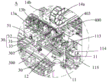
图1a是本发明所述自动贴标生产线的立体示意图。Fig. 1a is a schematic perspective view of the automatic labeling production line according to the present invention.
图1b是图1a中A部分的放大示意图。Fig. 1b is an enlarged schematic view of part A of Fig. 1a.
图2a是本发明自动贴标生产线的俯视图。Figure 2a is a top view of the automatic labeling production line of the present invention.
图2b是图2a中B部分的放大图。Figure 2b is an enlarged view of part B in Figure 2a.
图2c是图2a中C部分的放大图。Figure 2c is an enlarged view of part C in Figure 2a.
图3是本发明所述上料输送装置之翻转上料台闲置的部分结构示意图。FIG. 3 is a partial structural schematic diagram of the inversion feeding table of the feeding conveying device according to the present invention being idle.
图4是本发明所述上料输送装置之翻转上料台使用的一个状态示意图。FIG. 4 is a state schematic diagram of the use of the overturned feeding table of the feeding and conveying device according to the present invention.
图5是本发明所述上料输送装置之翻转上料台使用的另一状态示意图。FIG. 5 is another state schematic diagram of the use of the overturning feeding table of the feeding and conveying device according to the present invention.
图6是本发明所述翻转上料台的结构示意图。FIG. 6 is a schematic structural diagram of the overturning feeding table according to the present invention.
图7是本发明所述翻转上料台另一角度的结构示意图。FIG. 7 is a schematic structural diagram of another angle of the inversion feeding table according to the present invention.
图8是本发明所述吸嘴机器人的结构示意图。FIG. 8 is a schematic structural diagram of the nozzle robot according to the present invention.
图9是本发明所述吸嘴机器人中第一抓取组和第二抓取组的结构示意图。FIG. 9 is a schematic structural diagram of the first grasping group and the second grasping group in the nozzle robot according to the present invention.
图10是本发明所述上料机构的结构示意图。Figure 10 is a schematic structural diagram of the feeding mechanism of the present invention.
图11是本发明所述上料机构的部分结构示意图。Fig. 11 is a partial structural schematic diagram of the feeding mechanism according to the present invention.
图12是本发明所述标签输送装置的结构示意图。FIG. 12 is a schematic structural diagram of the label conveying device according to the present invention.
图13是本发明所述自动贴标生产线的部分示意图。13 is a partial schematic diagram of the automatic labeling production line of the present invention.
具体实施方式Detailed ways
为详细说明本发明的技术内容、构造特征、所实现目的及效果,以下结合实施方式并配合附图详予说明。In order to describe the technical content, structural features, achieved objects and effects of the present invention in detail, the following detailed description is given in conjunction with the embodiments and the accompanying drawings.
参考图1a和图2a,本发明公开了一种自动贴标生产线100,用于固态硬盘中内存条的贴标,包括生产传输线300、设于生产传输线300上并承载内存条的物料夹具30、沿所述生产传输线300的输送方向依次设置的上料工位301、贴标工位302、设置于所述上料工位301对应位置的上料输送装置10和设置有所述贴标工位302对应位置的贴标机20,所述上料输送装置10抓取内存条并将内存条从一取料台400输送至上料工位301,所述贴标机20打印标签,并将打印好的标签并输送至贴标工位302之预设位置的内存条上完成贴标。当然,本发明也可以用于其他物料贴标,并不限制在内存条。Referring to FIGS. 1a and 2a, the present invention discloses an automatic
参考图1b、图2c、图3至图6,所述上料输送装置10包括物料传输机构(13a、13b、14a、14b)、翻转上料台11和固定上料台12,所述固定上料台12上设置有可移动或位于第一位置D1的第一物料夹具121,所述第一物料夹具121用于固定内存条,所述翻转上料台11包括沿一竖直设置的第一转动轴M1转动安装于机架上的转动架111、沿竖直方向滑动安装于所述转动架111上的滑动架112、沿一水平设置的第二转动轴M2转动安装于所述滑动架112上的第二物料夹具113、带动所述第二物料夹具113沿第二转动轴M2转动的翻转驱动部114,以及带动所述滑动架112沿所述转动架111升降的升降驱动部115,所述第二物料夹具113用于固定内存条,所述转动架111带动所述第二物料夹具113在第一位置D1和第二位置D2之间转动,所述物料传输机构抓取内存条并将内存条从一取料台400移动至所述第一位置D1,将内存条从所述第一物料夹具121移动至上料工位301,所述贴标机20安装于所述贴标工位302的对应位置并打印标签,所述贴标机20构抓取标签并将标签从所述贴标机20输送至贴标工位302处的内存条上完成贴标。Referring to Fig. 1b, Fig. 2c, Fig. 3 to Fig. 6, the feeding and conveying
参考图6和图7,所述第二物料夹具113悬设于所述滑动架112上并可在所述升降驱动部115的带动下,在所述第一物料夹具121所在的第一水平高度和一高于所述第一水平高度的第二水平高度之间升降动作,所述翻转驱动部114可带动所述第二物料夹具113在第二水平高度进行180度翻转,且其翻转区域高于所述第一水平高度。Referring to FIG. 6 and FIG. 7 , the
参考图4和图5所述固定上料台12包括移动机构122和与所述移动机构122相连的第一物料夹具121,所述移动机构122带动所述第一物料夹具121在第一位置D1和第三位置D3之间移动。移动机构122包括驱动部和滑动轨道,第一物料夹具121滑动安装于该滑动轨道上,驱动部带动第一物料夹具121沿该滑动轨道滑动,以在第一位置D1和第三位置D3之间移动。Referring to FIGS. 4 and 5 , the fixed feeding table 12 includes a moving
参考图3至图7,工作时,若在贴标前需要对内存条进行翻转,则将翻转上料台11转动至第一位置(如图4所示),初始状态下,第二物料夹具113位于第三位置D3,翻转上料台11位于第一水平高度,且第二物料夹具113的定位面朝上设置(如图7所示),物料传输机构将内存条从取料台400移动至第二物料夹具113上,升降驱动部115带动第二物料夹具113上升至第二水平高度,翻转驱动部114可带动所述第二物料夹具113在第二水平高度进行180度翻转,与此同时,移动机构122带动第一物料夹具121移动至第一位置D1,第二物料夹具113翻转后,升降驱动部115带动第二物料夹具113下降至第一水平高度,第二物料夹具113释放内存条,第一物料夹具121固定内存条,以将内存条转移至第一物料夹具121上(如图5所示),移动机构122带动第一物料夹具121移动至第三位置D3(如图4所示),另一物料传输机构将内存条从第三位置D3移动至上料工位301处的物料夹具30上。若在贴标前不需要对内存条进行翻转,则将翻转上料台11转动至第二位置D2(如图3所示),物料传输机构将内存条从取料台400移动至第一位置D1处的第一物料夹具121上。当然,具体翻转或者不翻转时的工艺并不限制于上述实施例,只需确保在翻转时使得第二物料夹具113处于第一位置D1,在无需翻转时使得第二物料夹具113处于第二位置D2即可。Referring to Fig. 3 to Fig. 7, during operation, if the memory stick needs to be turned over before labeling, turn the turning table 11 to the first position (as shown in Fig. 4). In the initial state, the
参考图7,所述第二物料夹具113、第一物料夹具121以及物料夹具均包括夹具本体31和开设于所述夹具本体31底面上的限位槽32,且所述限位槽32的槽底开设有与抽真空管道连通的抽真空孔33,所述内存条可安装于所述限位槽32内并吸附于所述限位槽32的槽底上。本实施例中,每一夹具本体31上设置有六个限位槽32,六个限位槽32以三个为一排设置。本实施例中,物料夹具30与第二物料夹具113和第一物料夹具121结构相同。Referring to FIG. 7 , the
参考图5和图6,所述转动架111上开设有供抽真空管11b通过的避空定位槽11a。该避空定位槽11a为绕第二转动轴M2的弧形槽。Referring to FIG. 5 and FIG. 6 , the
本实施例中,升降驱动部115和翻转驱动部114均为旋转电机,当然也可以采用其他驱动方式。In this embodiment, the
参考图1b、图2c和图8,所述物料传输机构包括吸嘴机器人13a、吸嘴机器人14b,所述吸嘴机器人13a吸取内存条并通过三维机械手14a在第一位置D1和取料台400之间移动,吸嘴机器人14b吸取内存条并通过三维机械手14b在第三位置D3和上料工位301之间移动。1b, 2c and 8, the material transfer mechanism includes a
参考图8,所述吸嘴机器人13a包括抓取架131、安装于所述抓取架131上的第一吸嘴驱动部132、第一抓取组133、第二抓取组134,所述第一抓取组133沿X方向滑动安装于所述抓取架131上并可相对于所述第二抓取组134动作,所述第一吸嘴驱动部132带动所述第一抓取组133相对于第二抓取组134在所述抓取架131上移动,所述第一抓取组133和第二抓取组134上设置有一个或者多个吸取内存条的吸盘135,且所述第一抓取组133或第二抓取组134具有多个吸盘135时,多个所述吸盘135沿垂直于X方向的Y方向设置,且所述吸盘135朝向X方向设置,所述X方向、Y方向、Z方向相互垂直。Referring to FIG. 8 , the
参考图8,所述吸嘴机器人13a还包括第二吸嘴驱动部136,所述第二抓取组134沿与所述第一抓取组133平行的方向滑动安装于所述抓取架131上,所述第二吸嘴驱动部136带动所述第二抓取组134沿所述抓取架131滑动。Referring to FIG. 8 , the
参考图9,所述第一抓取组133和第二抓取组134均包括滑动导轨138、以一定间距滑动安装于所述滑动导轨138上的三个固定块137、沿所述滑动导轨138设置的转动轴139a、带动所述转动轴转动的转动驱动部139,每一固定块137上设置一吸盘135,所述固定块137上设置有滑块137a,所述转动轴上设置有三个与所述固定块137对应并供所述滑块137a滑动的滑槽,中间所述固定块137对应的滑槽为绕所述转动轴周向的环形沟槽138a,两侧的两所述固定块137对应的滑槽为绕所述转动轴的螺旋槽138b,且所述螺旋槽138b的螺旋方向相反。Referring to FIG. 9 , the
参考图10,所述自动贴标生产线100还包括上料机构40,上料机构40具有取料台400,可提供装载有内存条的料盘供物料传输机构取料。上料机构40包括料盘分离装置41、输送装置42、堆叠装置43、夹持装置44、装料工位401、分料工位402、取料工位403和堆叠工位404,料盘分离装置41在装料工位401上料以装载堆叠好的料盘200,在分料工位402将料盘200逐一分开,输送装置42将料盘200从分料工位402输送至取料工位403,夹持装置44夹持固定料盘200以待相上料输送装置10抓取料盘200上的内存条,抓取完毕后,输送装置42将空的料盘200输送至堆叠工位43,堆叠装置43将料盘200依次堆叠。其中,取料工位403位于取料台400。Referring to FIG. 10 , the automatic
参考图10,为了节省空间且便于电子器件抓取,堆叠工位404位于分料工位402的正上方,取料工位403位于堆叠工位404侧方并与堆叠工位403并行设置,在取料工位403的正下方增加升降工位405,输送装置42需要将料盘200从分料工位402输送至升降工位405,然后从升降工位405输送至取料工位403。Referring to FIG. 10 , in order to save space and facilitate the grasping of electronic devices, the stacking
参考图10和图11,所述料盘分离装置41包括安装架411、移动架412、分料装置、承载台414、升降驱动机构415,所述安装架411位于分料工位402,所述移动架412可相对于所述安装架411在所述分料工位402和装料工位401之间滑动,所述移动架412上形成有物料放置区,物料放置区用于放置料盘叠。所述分料装置包括活动安装于所述移动架上412并可伸入所述物料放置区以承载料盘200的分料块416、安装于所述安装架411上并与所述分料块416位置对应的分料驱动部417。其中,分料块416和分料驱动部417之间设置有相互配合的卡合组件418、419,以使所述移动架412位于所述分料工位402时,所述分料驱动部417与分料块416卡合连接,分料驱动部417带动分料块416伸缩动作,以承载、释放料盘200。所述承载台414安装于所述分料工位402处并位于料盘放置区下方,所述升降驱动机构415415带动所述承载台414升降动作以承载料盘200。本实施例中,分料块416的末端呈楔形。本实施例中,分料块416滑动安装于移动架412上,分料驱动部417为升降驱动部,例如伸缩气缸等等。10 and 11 , the
参考图10和图11,工作时,移动架412滑出安装架411移动至装料工位401装载料盘叠,装载完成后移动架返回安装架412以移动至分料工位402,分料块416和分料驱动部417相互卡合以使分料驱动部417可带动分料块416动作,传感器检测到料盘叠到位以开始分料工作:升降驱动机构415控制承载台414上升以承载料盘叠,分料驱动部417拉动分料块416远离物料放置区,以使得分料块416退出物料放置区以释放料盘叠,料盘叠落入承载台414上,升降驱动机构415控制承载台414下降预设距离(近似一个料盘厚度),使得料盘叠最底下的料盘低于分料块416所在高度,分料驱动部417动作以使得分料块416伸入物料放置区,此时分料块416伸入倒数第二层料盘的下方(倒数第一层料盘和倒数第二层料盘之间),升降驱动机构415带动承载台414下降至初始位置,倒数第二层料盘承载于分料块416上,即新的料盘叠承载于分料块416上,倒数第一层料盘被分离出来。Referring to FIGS. 10 and 11 , during operation, the moving
参考图11,输送装置42包括输送带421,输送带421包括位于所述承载台414两相对侧的第一部分4211,所述第一部分4211的两相对侧位于物料放置区下方的覆盖范围内,以使承载最后一层料盘的所述承载台414下降时,所述料盘可随之承载于所述第一部分4211上并脱离承载台414,此时输送带动作,第一部分4211可带动其上的料盘从装料工位401输送出来。其中,所述输送带421还包括第二部分4212,第二部分4212的前端和第一部分4211的末端相接,并将所述第一部分4211输出的料盘输送至升降工位405。Referring to FIG. 11 , the conveying
其中,移动架412和安装架411之间设置有相互配合的滑动组件,以使移动架412相对于安装架411滑动,该滑动组件包括滑轨和滑动安装于滑轨中的滑片。Wherein, a sliding assembly that cooperates with each other is provided between the moving
参考图11,分料块416设置于所述物料放置区边沿,通过滑动导轨滑动安装于移动架412上并可相对于物料放置区伸缩滑动。分料块416具有多个并分布于所述物料放置区的至少两相对侧。本实施例中,分料块416有四个,并分别设置于物料放置区左右两侧的两端(临近物料放置区的四角)。所述装料工位401与分料工位402并排设置,该方案中移动架412相对于安装架411沿水平方向滑动。当然,装料工位401与分料工位402之间也可以具有一定高度差,或者具有一定角度,此时移动架412沿弧形轨道相对于安装架411滑动。Referring to FIG. 11 , the
参考图11,物料放置区由竖直设置于移动架412上的多个限位块4121相对围成,所述限位块4121上形成有位置相对的限位槽。本实施例中,四个限位块4121的限位槽相对并围成物料放置区。Referring to FIG. 11 , the material placement area is relatively surrounded by a plurality of
参考图10和图11,所述卡合组件包括与所述分料块416相连的卡合件418、与分料驱动部417的输出件相连并可与卡合件418卡合连接的卡合驱动块419,所述卡合件418上形成有沿所述移动架412的滑动方向延伸并朝向所述物料放置区方向的卡合边,所述卡合驱动块419可伸入所述卡合边内侧并与所述卡合边卡合,其中,所述卡合驱动块419可随所述移动架412向所述分料工位402滑动而逐渐伸入所述卡合边内侧以与所述卡合边卡合连接,所述分料驱动部417带动所述卡合驱动块419动作以通过所述卡合件418带动所述分料块416相对于物料放置区移动,以使所述分料块416可伸入或退出所述物料放置区。Referring to FIGS. 10 and 11 , the engaging component includes an engaging
其中,所述分料块416与所述移动架412之间还连接有复位弹簧(图中未示),所述复位弹簧对所述分料块416提供伸入所述物料放置区的弹力。当然,也可以使用卡合槽和伸入卡合槽的卡合滑块的组合代替卡合件418和卡合驱动块419,此时分料驱动部417通过卡合槽和卡合滑块组成的卡合组件直接带动分料块416伸缩动作。Wherein, a return spring (not shown in the figure) is also connected between the
参考图10,所述卡合件418于远离所述物料放置区的一侧形成有一沿所述移动架412滑动方向延伸的卡合区域,该卡合区域朝向所述分料工位402的一侧具有开口,所述卡合边形成于所述卡合区域朝向所述物料放置区的侧面,随着所述移动架412向所述分料工位402滑动,所述卡合驱动块419可沿所述开口伸入所述卡合区域。Referring to FIG. 10 , the engaging
为了进一步实现自动化生产,料盘分离装置还包括上料驱动部,所述上料驱动部安装于所述安装架411上并可带动所述移动架412在所述分料工位402和装料工位401之间滑动。其中,所述上料驱动部包括旋转驱动部、啮合齿轮和直齿条,所述直齿条安装于所述移动架412上并具有与所述啮合齿轮啮合的若干齿牙,所述旋转驱动部与所述啮合齿轮相连并带动所述啮合齿轮转动,从而带动所述直齿条移动,所述直齿条带动所述移动架412在所述分料工位402和装料工位401之间滑动。其中,移动架412和安装架411之间还设置有直齿条的移动进行限位的限位组件。In order to further realize automated production, the tray separation device further includes a feeding drive part, which is installed on the mounting
参考图10,输送装置42包括升降机构,升降机构包括第一升降驱动部、升降输送带和连接于所述升降输送带上并支撑料盘的第一支撑件,所述第一升降驱动部带动所述升降输送带移动,所述升降输送带沿竖直方向设置并带动所述第一支撑件在所述升降工位405和取料工位404之间移动。第二部分将料盘输送至升降工位405时,第一支撑件位于料盘下方,第一升降驱动部带动升降输送带正传,升降输送带带动第一支撑件上升以将升降工位405处的料盘升至取料工位404。Referring to FIG. 10 , the conveying
参考图10,输送装置42包括横向输送机构422,横向输送机构422包括安装于机架上的横向输送带、带动所述横向输送带转动的横向驱动部、安装于所述横向输送带上的输送支架4221,以及转动安装于所述输送支架4221上并可推动所述料盘200向所述堆叠工位404方向移动的推动部4222,所述横向驱动部带动所述横向输送带动作,所述横向输送带带动所述推动部4222在所述取料工位404和所述堆叠工位404之间移动,以将所述料盘200推动至所述堆叠工位404。其中,输送支架4221滑动连接于机架的滑动导轨上,横向驱动部安装于机架上。本实施例中,横向驱动部通过横向输送带带动输送支架移动,在其他实施例中,可以通过其他的传动机构带动输送之间移动,并不限制于上述实施例。Referring to FIG. 10 , the conveying
参考图10,所述推动部4222包括位于所述推动部4222之转动轴422a一端的推块422b和位于所述转动轴422a另一端的配重块422c,所述配重块422c可带动所述推块上升至与所述取料工位404处的料盘对应的推动位置(如图中的A部分以及附图b所示),所述输送支架4221于背对所述堆叠工位404的一侧形成有临近所述推块422b的限位部422d和临近所述配重块422c的避空槽422e,所述限位部422d限制所述推动部4222转动位置以防止所述推动部4222向远离所述堆叠工位404一侧转动至推动位置以下,所述避空槽422e为所述配重块422c提供容纳空间以使所述推块422b可在朝向所述堆叠工位404的力的作用下转动至所述推动位置以下。Referring to FIG. 10 , the pushing
参考图10,当取料工位404上的料盘上电子器件被抓取完毕后,夹持装置44释放料盘,此时,推动部4222位于取料工位404的后侧(料盘后侧),横向驱动部带动横向输送带正向动作,横向输送带带动推动部向堆叠工位404移动,推块从后侧抵推料盘的后边沿并将料盘推至堆叠工位404,此时推块位于堆叠工位404后边沿处(如图10中的A1部分所示),横向驱动部带动横向输送带反向动作,横向输送带带动推动部向取料工位404移动,由于有新的料盘移动至取料工位404,故新的料盘抵推推块使得推块向下转动至推动位置下(如图10中的A2部分所示),推动部从料盘下方复位至取料工位404的后边沿处,并在配重块的作用下向上转动至推动位置。Referring to FIG. 10 , after the electronic device on the tray on the reclaiming
参考图10,所述推动部4222背对所述堆叠工位404的一侧形成有第一导向面,料盘200的边沿以及下表面可相对于所述第一导向面滑动,并带动推定部4222的推块向下转动。Referring to FIG. 10 , a first guide surface is formed on the side of the pushing
参考图10,所述堆叠装置43包括形成堆叠工位404的堆叠安装架431、堆叠驱动部432、堆叠支撑件(图中未示)、安装于所述堆叠安装架431上并位于所述堆叠工位404至少两相对边沿的多个支撑块433,以及安装于支撑块433和堆叠安装架431之间的弹性件434,所述支撑块433可相对于所述堆叠安装架431转动,并可向下转动至下限位以伸入所述堆叠工位404并支撑料盘(如图和图所示),可向上转动以退出所述堆叠工位404(图中未示),所述堆叠支撑件(图中未示)位于所述堆叠工位404下方并支撑所述堆叠工位404处的料盘,且所述堆叠支撑件与所述支撑块433位置错开,所述堆叠驱动部432与所述堆叠支撑件相连并带动所述堆叠支撑架升降动作,以将所述堆叠工位404处的料盘上升至所述支撑块433以上,该弹性件434对支撑块433提供向下旋转以伸入堆叠工位404的弹力。Referring to FIG. 10 , the stacking device 43 includes a stacking mounting frame 431 forming a stacking station 404 , a stacking driving part 432 , a stacking supporter (not shown in the figure), mounted on the stacking mounting frame 431 and located in the stacking A plurality of support blocks 433 on at least two opposite edges of the station 404, and an elastic member 434 installed between the support blocks 433 and the stacking mounting frame 431, the support blocks 433 can rotate relative to the stacking mounting frame 431, and can Rotate down to the lower limit to extend into the stacking station 404 and support the tray (as shown in the figure and the figure), and can be rotated upward to exit the stacking station 404 (not shown in the figure), the stacking support A component (not shown in the figure) is located below the stacking station 404 and supports the tray at the stacking station 404, and the stacking supporting member and the supporting block 433 are staggered, and the stacking driving part 432 is connected to the The stacking support members are connected and drive the stacking support frame to move up and down, so as to lift the tray at the stacking station 404 above the support block 433 , and the elastic member 434 provides the support block 433 with downward rotation to rotate. Resilience that extends into the stacking
参考图10,支撑块433的上表面为支撑面,下表面为可供料盘滑动的第二导向面,料盘可相对于导向面滑动并带动支撑块433向上转动以脱离堆叠工位404,该第二导向面由下向上逐渐向堆叠工位404延伸以使得支撑块433呈楔形。Referring to FIG. 10 , the upper surface of the
参考图10,当空料盘200被输送至堆叠工位404时,支撑块433上支撑有料盘叠,堆叠支撑件(图中未示)位于该料盘下方,堆叠驱动部432带动堆叠支撑件上升,堆叠支撑件顶推料盘使得料盘向上移动,料盘移动至支撑块433处可抵推支撑块433的第二导向面以带动支撑块433向上旋转以脱离堆叠工位404,堆叠支撑件通过该料盘承载料盘叠,且该料盘被堆叠至料盘叠最下方,堆叠支撑件带动料盘叠继续上升,直至料盘叠的最下方到达支撑块433的转动路径以上,支撑块433在弹性件434的带动下向下转动并伸入堆叠工位404,堆叠驱动部432带动堆叠支撑件下降至初始位置,新的料盘叠被支撑块433阻挡并支撑于支撑块433上,实现料盘的堆叠工作。Referring to FIG. 10 , when the
参考图12和图13,所述贴标机20包括标签打印机21和标签抓取机构22,所述标签打印机21打印标签,所述标签抓取机构22抓取打印好的标签并输送至贴标工位302之预设位置的内存条上完成贴标。所述标签抓取机构22包括标签输送部和三维机械手14c,标签输送部抓取标签并将所述标签通过三维机械手14c(图中未示)输送至贴标工位302。12 and 13, the
参考图12和图13,为了缩短三维机械手14c的移动行程,标签打印机21出口设置有标签输送装置23,标签输送装置23的前端接标签打印机21出口,标签输送装置23承载标签并将标签粘贴面朝下的输送至末端,标签输送部抓取标签并将所述标签通过三维机械手14(图中未示)输送至贴标工位302。12 and 13, in order to shorten the moving stroke of the three-
参考图13,贴标机20还包括位置检测装置24,标签抓取机构22抓取标签后途径位置检测装置24,位置检测装置24检测标签在标签抓取机构22上的位置,系统依据该位置控制标签抓取机构22动作,使得标签抓取机构22将标签转动预设角度并将标签准确输送至贴标工位302(图中未示)。标签抓取机构22包括吸盘、带动吸盘转动的转动部和带动转动部沿X轴方向、Y轴方向和Z轴方向移动的三维机械手14c。Referring to FIG. 13 , the
参考图图13,所述贴标机20还包括不合格品处理台25和视觉检测装置26,所述不合格品处理台25临近所述标签输送装置23的取料端设置,视觉检测装置26位于所述标签输送装置23输送标签的路径上并扫描标签,检测标签是否有误,若是则系统控制标签抓取机构22抓取标签,将标签输送粘粘至不合格品处理台25,若否则系统控制标签抓取机构22抓取标签,标签抓取机构22抓取标签并途径位置检测装置24并向贴标工位302输送,位置检测装置24检测标签在标签抓取机构22上的位置,系统依据该位置控制标签抓取机构22动作,使得转动预设角度并将标签准确输送至贴标工位302。Referring to FIG. 13 , the
参考图12,标签输送装置23用于输送标签,包括安装于机架上的驱动机构231和输送带232,所述驱动机构231带动所述输送带232移动。所述输送带232由若干个以一定间距沿输送带232横向方向设置的传输线体232a并排设置而成,相邻传输线体232a之间形成贯穿沟槽232b,传输线体232a的上半部分形成输送带232上的条形凸起,标签背面朝下承载于条形凸起上。Referring to FIG. 12 , the
参考图12,本实施例中,该传输线体232a为圆线,条形凸起的顶部为弧形。该圆线可以为横截面为圆形、椭圆形甚至异形圆。当然,在另一实施例中,传输线体232a为扁线,其横截面为正方向或长方形。传输线体232a也可以为横截面为多边形的线体,例如六边形、五边形等等。Referring to FIG. 12 , in this embodiment, the
参考图12,所述驱动机构231包括驱动部231a、分别设置于所述输送带232前后两端的驱动辊轴231b,所述驱动部231a带动所述驱动辊轴231b转动,若干所述传输线体232a分别缠绕于所述驱动辊轴231b上,并在所述驱动辊轴231b的带动下循环转动。Referring to FIG. 12 , the
参考图12,所述驱动辊轴231b包括设置于所述输送带232末端的第一驱动辊轴、设置于所述输送带232前端上下两侧的第二驱动辊轴和第三驱动辊轴,所述驱动机构231还包括设置于所述输送带232下方中间的张紧辊轴。12, the driving
参考图12,所述驱动辊轴231b沿其轴向设置若干个与所述传输线体232a对应的环状容纳槽231c。环状容纳槽231c增加了传输线体232a和驱动辊轴231b之间的摩擦力,防止打滑,当然,可以通过增加驱动辊轴231b处(环状容纳槽231c的表面)与传输线体232a上的摩擦系数(例如通过材料、涂层、花纹等方式)来增加传输线体232a和驱动辊轴231b之间的摩擦力。Referring to FIG. 12 , the driving
参考图12,所述输送带232末端形成抓取标签区域,标签抓取机构22抓取该抓取标签区域的标签。所述标签输送装置23还包括升降顶板233,所述升降顶板233安装于所述抓取标签区域,且其上设置有若干个与所述贯穿沟槽232b位置对应且可从下至上穿过所述贯穿沟槽232b的顶块233a,所述升降顶板233可在一升降驱动部233b的带动下升降动作,以使所述顶块233a穿过所述贯穿沟槽232b顶起输送带232上的标签。使得取料时,升降驱动部233b带动升降顶板233向上升,顶块233a穿过贯穿沟槽232b以将标签从输送带232顶起,以使标签和输送带232脱离,此时输送带232可继续运行,以输送标签打印机打印好的标签,升降顶板233等待标签抓取机构22抓取标签。Referring to FIG. 12 , the end of the
在一优先实施例中,每一所述顶块233a的上表面开设有至少一个与抽真空管道连接的抽真空孔(图中未示),所述顶块233a顶推标签并可通过抽真空孔吸住所述标签。In a preferred embodiment, the upper surface of each
参考图12,所述抓取标签区域对应的位置上开设有检测标签的检测器234,该检测器234检测所述抓取标签区域是否具有标签。Referring to FIG. 12 , a
参考图12,所述标签输送装置23还包括压带板235,所述压带板235位于所述输送带232的上方与所述抓取标签区域对应的位置,所述压带板235与输送带232上表面具有一定间隙,且所述压带板235上开设有供所述顶块233a穿过的槽孔。Referring to FIG. 12 , the
参考图12,所述标签输送装置23还包括支撑板236,所述支撑板236设于所述输送带232内并支撑输送带232上半部分的下表面,且所述支撑板236与所述抓取标签区域对应的位置开设有避空槽。12, the
参考图1a和图2a,自动贴标生产线100还包括扫描机构51、回收机构52、滚压机构53、下料机构54,扫描机构51具有多个,分别包括设于上料工位附近并检测未贴标的内存条以及对应物料机构的第一扫描机构,安装于贴标工位前并通过检测承载内存条的物料夹具30来记录内存条的编码的第二扫描机构,安装于下料工位303处并检测内存条贴标是否有误的第三扫描机构。扫描机构51、回收机构52、滚压机构53、下料机构54的具体结构和工作过程可参考中国专利CN201820497624.2以及其他现有技术,在此不予详述1a and FIG. 2a, the automatic
以上所揭露的仅为本发明的优选实施例而已,当然不能以此来限定本发明之权利范围,因此依本发明申请专利范围所作的等同变化,仍属本发明所涵盖的范围。The above disclosures are only the preferred embodiments of the present invention, and of course, it cannot limit the scope of the rights of the present invention. Therefore, the equivalent changes made according to the scope of the patent application of the present invention are still within the scope of the present invention.
Claims (10)
Priority Applications (1)
| Application Number | Priority Date | Filing Date | Title |
|---|---|---|---|
| CN202011054753.2A CN112009837B (en) | 2020-09-29 | 2020-09-29 | Feeding conveying device and automatic labeling production line |
Applications Claiming Priority (1)
| Application Number | Priority Date | Filing Date | Title |
|---|---|---|---|
| CN202011054753.2A CN112009837B (en) | 2020-09-29 | 2020-09-29 | Feeding conveying device and automatic labeling production line |
Publications (2)
| Publication Number | Publication Date |
|---|---|
| CN112009837A true CN112009837A (en) | 2020-12-01 |
| CN112009837B CN112009837B (en) | 2025-05-06 |
Family
ID=73527629
Family Applications (1)
| Application Number | Title | Priority Date | Filing Date |
|---|---|---|---|
| CN202011054753.2A Active CN112009837B (en) | 2020-09-29 | 2020-09-29 | Feeding conveying device and automatic labeling production line |
Country Status (1)
| Country | Link |
|---|---|
| CN (1) | CN112009837B (en) |
Cited By (3)
| Publication number | Priority date | Publication date | Assignee | Title |
|---|---|---|---|---|
| CN112389724A (en) * | 2020-12-03 | 2021-02-23 | 东江精创注塑(深圳)有限公司 | Automatic paste multiaspect protection film equipment |
| CN112721116A (en) * | 2020-12-29 | 2021-04-30 | 苏州凯尔博精密机械有限公司 | Multifunctional IMG (in-mold decoration) forming assembly line |
| CN118083301A (en) * | 2023-09-19 | 2024-05-28 | 温州崇尚机械科技有限公司 | Tax stamp labeling machine |
Citations (8)
| Publication number | Priority date | Publication date | Assignee | Title |
|---|---|---|---|---|
| JPH08290825A (en) * | 1995-04-20 | 1996-11-05 | Toshiba Corp | Work reversing device, work reversing method, work processing device |
| CN207208708U (en) * | 2017-08-29 | 2018-04-10 | 深圳市华东兴科技有限公司 | A kind of electronic product automatic turning device |
| CN108408175A (en) * | 2018-04-09 | 2018-08-17 | 东莞市沃德精密机械有限公司 | Full automatic high efficiency labelling machine |
| CN108545278A (en) * | 2018-04-09 | 2018-09-18 | 东莞市沃德精密机械有限公司 | The High-Speed Automatic labeling production line of solid state disk |
| EP3476782A1 (en) * | 2017-10-27 | 2019-05-01 | Heino Ilsemann GmbH | Device for transferring objects and method |
| CN209668153U (en) * | 2019-02-12 | 2019-11-22 | 深圳智赛机器人有限公司 | A kind of reclaimer device and automatic attaching system |
| CN211003400U (en) * | 2019-11-12 | 2020-07-14 | 东莞市绿科塑胶制品有限公司 | Automatic sticking film machine turn over palm extracting mechanism |
| CN212423759U (en) * | 2020-09-29 | 2021-01-29 | 东莞市沃德精密机械有限公司 | Material loading conveyor and automatic labeling production line |
-
2020
- 2020-09-29 CN CN202011054753.2A patent/CN112009837B/en active Active
Patent Citations (8)
| Publication number | Priority date | Publication date | Assignee | Title |
|---|---|---|---|---|
| JPH08290825A (en) * | 1995-04-20 | 1996-11-05 | Toshiba Corp | Work reversing device, work reversing method, work processing device |
| CN207208708U (en) * | 2017-08-29 | 2018-04-10 | 深圳市华东兴科技有限公司 | A kind of electronic product automatic turning device |
| EP3476782A1 (en) * | 2017-10-27 | 2019-05-01 | Heino Ilsemann GmbH | Device for transferring objects and method |
| CN108408175A (en) * | 2018-04-09 | 2018-08-17 | 东莞市沃德精密机械有限公司 | Full automatic high efficiency labelling machine |
| CN108545278A (en) * | 2018-04-09 | 2018-09-18 | 东莞市沃德精密机械有限公司 | The High-Speed Automatic labeling production line of solid state disk |
| CN209668153U (en) * | 2019-02-12 | 2019-11-22 | 深圳智赛机器人有限公司 | A kind of reclaimer device and automatic attaching system |
| CN211003400U (en) * | 2019-11-12 | 2020-07-14 | 东莞市绿科塑胶制品有限公司 | Automatic sticking film machine turn over palm extracting mechanism |
| CN212423759U (en) * | 2020-09-29 | 2021-01-29 | 东莞市沃德精密机械有限公司 | Material loading conveyor and automatic labeling production line |
Cited By (3)
| Publication number | Priority date | Publication date | Assignee | Title |
|---|---|---|---|---|
| CN112389724A (en) * | 2020-12-03 | 2021-02-23 | 东江精创注塑(深圳)有限公司 | Automatic paste multiaspect protection film equipment |
| CN112721116A (en) * | 2020-12-29 | 2021-04-30 | 苏州凯尔博精密机械有限公司 | Multifunctional IMG (in-mold decoration) forming assembly line |
| CN118083301A (en) * | 2023-09-19 | 2024-05-28 | 温州崇尚机械科技有限公司 | Tax stamp labeling machine |
Also Published As
| Publication number | Publication date |
|---|---|
| CN112009837B (en) | 2025-05-06 |
Similar Documents
| Publication | Publication Date | Title |
|---|---|---|
| CN112010048B (en) | Tray separation device and feeding equipment | |
| CN113816152A (en) | An uninterrupted feeder and MTF test equipment | |
| CN110422416A (en) | An integrated circuit and its film tearing method and film-tearing arrangement equipment | |
| CN213264681U (en) | Feed tray separation device and feeding equipment | |
| CN115123815B (en) | Automatic feeding and discharging test equipment | |
| CN115339903A (en) | Workpiece feeding device and method | |
| CN112009837B (en) | Feeding conveying device and automatic labeling production line | |
| CN116588676A (en) | Material transfer device and solar cell production equipment | |
| CN110636714B (en) | PCB board taping machine | |
| CN110282378B (en) | Automatic feeding and discharging machine for AVI (automatic video inspection) machine | |
| CN212423759U (en) | Material loading conveyor and automatic labeling production line | |
| CN117583259A (en) | Three-temperature test sorting equipment | |
| CN208133774U (en) | The full-automatic mounting line of multilayer dose | |
| CN210456329U (en) | Automatic feeding and discharging machine for AVI detection machine | |
| CN216971312U (en) | Loading and unloading device and system | |
| CN1887669A (en) | Unpacking system and method for glass plate | |
| CN116924032A (en) | Novel chip feeding structure | |
| CN211520950U (en) | A module board testing machine | |
| CN115593948B (en) | Screen blanking device and blanking method thereof | |
| CN207712449U (en) | A kind of feeding device of OLED material dyestripping equipment | |
| JP6974917B2 (en) | Nori supply device | |
| CN222966112U (en) | Silicon wafer limit lifting mechanism and silicon wafer transfer device | |
| CN223239162U (en) | Tray discharging mechanism, material discharging device and material detection equipment | |
| CN216548484U (en) | Automatic feeding device for PCB | |
| CN223174896U (en) | Loading and unloading device suitable for charging tray |
Legal Events
| Date | Code | Title | Description |
|---|---|---|---|
| PB01 | Publication | ||
| PB01 | Publication | ||
| SE01 | Entry into force of request for substantive examination | ||
| SE01 | Entry into force of request for substantive examination | ||
| CB02 | Change of applicant information | ||
| CB02 | Change of applicant information |
Country or region after: China Address after: No. 6, Wanjiang Section, Gangkou Avenue, Wanjiang Street, Dongguan City, Guangdong Province, 523000 Applicant after: Guangdong Ward Precision Technology Co.,Ltd. Address before: No. 8, Wanjiang Chuangye Industrial Road, Wanjiang Street, Dongguan City, Guangdong Province Applicant before: World Precision Manufacturing (Dongguan) Co.,Ltd. Country or region before: China |
|
| GR01 | Patent grant | ||
| GR01 | Patent grant |