CN111998295A - Photovoltaic solar illuminating lamp with electric power storage function - Google Patents
Photovoltaic solar illuminating lamp with electric power storage function Download PDFInfo
- Publication number
- CN111998295A CN111998295A CN202010888316.4A CN202010888316A CN111998295A CN 111998295 A CN111998295 A CN 111998295A CN 202010888316 A CN202010888316 A CN 202010888316A CN 111998295 A CN111998295 A CN 111998295A
- Authority
- CN
- China
- Prior art keywords
- heat dissipation
- mounting
- power storage
- led lamp
- mounting base
- Prior art date
- Legal status (The legal status is an assumption and is not a legal conclusion. Google has not performed a legal analysis and makes no representation as to the accuracy of the status listed.)
- Pending
Links
- 230000017525 heat dissipation Effects 0.000 claims abstract description 71
- 238000007789 sealing Methods 0.000 claims abstract description 23
- 238000009434 installation Methods 0.000 claims abstract description 16
- 238000003466 welding Methods 0.000 claims abstract description 3
- 210000001503 joint Anatomy 0.000 claims description 24
- 239000000428 dust Substances 0.000 claims description 22
- 238000009423 ventilation Methods 0.000 claims description 21
- 230000007246 mechanism Effects 0.000 claims description 11
- 239000004020 conductor Substances 0.000 claims description 6
- 238000012423 maintenance Methods 0.000 claims description 5
- 230000005611 electricity Effects 0.000 claims description 4
- 230000000149 penetrating effect Effects 0.000 claims description 4
- 230000005855 radiation Effects 0.000 claims description 3
- 238000000034 method Methods 0.000 claims description 2
- 238000005286 illumination Methods 0.000 abstract description 6
- 230000006978 adaptation Effects 0.000 abstract description 2
- 230000007613 environmental effect Effects 0.000 abstract description 2
- 230000008859 change Effects 0.000 description 2
- 230000001105 regulatory effect Effects 0.000 description 2
- 239000000126 substance Substances 0.000 description 2
- 238000010586 diagram Methods 0.000 description 1
- 230000000694 effects Effects 0.000 description 1
- 238000005516 engineering process Methods 0.000 description 1
- 230000006698 induction Effects 0.000 description 1
- 230000007774 longterm Effects 0.000 description 1
- 238000012986 modification Methods 0.000 description 1
- 230000004048 modification Effects 0.000 description 1
- 230000008569 process Effects 0.000 description 1
Images



Classifications
-
- F—MECHANICAL ENGINEERING; LIGHTING; HEATING; WEAPONS; BLASTING
- F21—LIGHTING
- F21S—NON-PORTABLE LIGHTING DEVICES; SYSTEMS THEREOF; VEHICLE LIGHTING DEVICES SPECIALLY ADAPTED FOR VEHICLE EXTERIORS
- F21S9/00—Lighting devices with a built-in power supply; Systems employing lighting devices with a built-in power supply
- F21S9/02—Lighting devices with a built-in power supply; Systems employing lighting devices with a built-in power supply the power supply being a battery or accumulator
- F21S9/03—Lighting devices with a built-in power supply; Systems employing lighting devices with a built-in power supply the power supply being a battery or accumulator rechargeable by exposure to light
- F21S9/035—Lighting devices with a built-in power supply; Systems employing lighting devices with a built-in power supply the power supply being a battery or accumulator rechargeable by exposure to light the solar unit being integrated within the support for the lighting unit, e.g. within or on a pole
-
- F—MECHANICAL ENGINEERING; LIGHTING; HEATING; WEAPONS; BLASTING
- F21—LIGHTING
- F21V—FUNCTIONAL FEATURES OR DETAILS OF LIGHTING DEVICES OR SYSTEMS THEREOF; STRUCTURAL COMBINATIONS OF LIGHTING DEVICES WITH OTHER ARTICLES, NOT OTHERWISE PROVIDED FOR
- F21V19/00—Fastening of light sources or lamp holders
-
- F—MECHANICAL ENGINEERING; LIGHTING; HEATING; WEAPONS; BLASTING
- F21—LIGHTING
- F21V—FUNCTIONAL FEATURES OR DETAILS OF LIGHTING DEVICES OR SYSTEMS THEREOF; STRUCTURAL COMBINATIONS OF LIGHTING DEVICES WITH OTHER ARTICLES, NOT OTHERWISE PROVIDED FOR
- F21V21/00—Supporting, suspending, or attaching arrangements for lighting devices; Hand grips
- F21V21/02—Wall, ceiling, or floor bases; Fixing pendants or arms to the bases
-
- F—MECHANICAL ENGINEERING; LIGHTING; HEATING; WEAPONS; BLASTING
- F21—LIGHTING
- F21V—FUNCTIONAL FEATURES OR DETAILS OF LIGHTING DEVICES OR SYSTEMS THEREOF; STRUCTURAL COMBINATIONS OF LIGHTING DEVICES WITH OTHER ARTICLES, NOT OTHERWISE PROVIDED FOR
- F21V21/00—Supporting, suspending, or attaching arrangements for lighting devices; Hand grips
- F21V21/10—Pendants, arms, or standards; Fixing lighting devices to pendants, arms, or standards
-
- F—MECHANICAL ENGINEERING; LIGHTING; HEATING; WEAPONS; BLASTING
- F21—LIGHTING
- F21V—FUNCTIONAL FEATURES OR DETAILS OF LIGHTING DEVICES OR SYSTEMS THEREOF; STRUCTURAL COMBINATIONS OF LIGHTING DEVICES WITH OTHER ARTICLES, NOT OTHERWISE PROVIDED FOR
- F21V29/00—Protecting lighting devices from thermal damage; Cooling or heating arrangements specially adapted for lighting devices or systems
- F21V29/50—Cooling arrangements
- F21V29/70—Cooling arrangements characterised by passive heat-dissipating elements, e.g. heat-sinks
- F21V29/74—Cooling arrangements characterised by passive heat-dissipating elements, e.g. heat-sinks with fins or blades
-
- F—MECHANICAL ENGINEERING; LIGHTING; HEATING; WEAPONS; BLASTING
- F21—LIGHTING
- F21V—FUNCTIONAL FEATURES OR DETAILS OF LIGHTING DEVICES OR SYSTEMS THEREOF; STRUCTURAL COMBINATIONS OF LIGHTING DEVICES WITH OTHER ARTICLES, NOT OTHERWISE PROVIDED FOR
- F21V29/00—Protecting lighting devices from thermal damage; Cooling or heating arrangements specially adapted for lighting devices or systems
- F21V29/50—Cooling arrangements
- F21V29/70—Cooling arrangements characterised by passive heat-dissipating elements, e.g. heat-sinks
- F21V29/83—Cooling arrangements characterised by passive heat-dissipating elements, e.g. heat-sinks the elements having apertures, ducts or channels, e.g. heat radiation holes
-
- F—MECHANICAL ENGINEERING; LIGHTING; HEATING; WEAPONS; BLASTING
- F24—HEATING; RANGES; VENTILATING
- F24S—SOLAR HEAT COLLECTORS; SOLAR HEAT SYSTEMS
- F24S30/00—Arrangements for moving or orienting solar heat collector modules
- F24S30/40—Arrangements for moving or orienting solar heat collector modules for rotary movement
- F24S30/42—Arrangements for moving or orienting solar heat collector modules for rotary movement with only one rotation axis
- F24S30/425—Horizontal axis
-
- H—ELECTRICITY
- H02—GENERATION; CONVERSION OR DISTRIBUTION OF ELECTRIC POWER
- H02S—GENERATION OF ELECTRIC POWER BY CONVERSION OF INFRARED RADIATION, VISIBLE LIGHT OR ULTRAVIOLET LIGHT, e.g. USING PHOTOVOLTAIC [PV] MODULES
- H02S20/00—Supporting structures for PV modules
- H02S20/30—Supporting structures being movable or adjustable, e.g. for angle adjustment
-
- F—MECHANICAL ENGINEERING; LIGHTING; HEATING; WEAPONS; BLASTING
- F21—LIGHTING
- F21Y—INDEXING SCHEME ASSOCIATED WITH SUBCLASSES F21K, F21L, F21S and F21V, RELATING TO THE FORM OR THE KIND OF THE LIGHT SOURCES OR OF THE COLOUR OF THE LIGHT EMITTED
- F21Y2115/00—Light-generating elements of semiconductor light sources
- F21Y2115/10—Light-emitting diodes [LED]
-
- Y—GENERAL TAGGING OF NEW TECHNOLOGICAL DEVELOPMENTS; GENERAL TAGGING OF CROSS-SECTIONAL TECHNOLOGIES SPANNING OVER SEVERAL SECTIONS OF THE IPC; TECHNICAL SUBJECTS COVERED BY FORMER USPC CROSS-REFERENCE ART COLLECTIONS [XRACs] AND DIGESTS
- Y02—TECHNOLOGIES OR APPLICATIONS FOR MITIGATION OR ADAPTATION AGAINST CLIMATE CHANGE
- Y02E—REDUCTION OF GREENHOUSE GAS [GHG] EMISSIONS, RELATED TO ENERGY GENERATION, TRANSMISSION OR DISTRIBUTION
- Y02E10/00—Energy generation through renewable energy sources
- Y02E10/40—Solar thermal energy, e.g. solar towers
- Y02E10/47—Mountings or tracking
-
- Y—GENERAL TAGGING OF NEW TECHNOLOGICAL DEVELOPMENTS; GENERAL TAGGING OF CROSS-SECTIONAL TECHNOLOGIES SPANNING OVER SEVERAL SECTIONS OF THE IPC; TECHNICAL SUBJECTS COVERED BY FORMER USPC CROSS-REFERENCE ART COLLECTIONS [XRACs] AND DIGESTS
- Y02—TECHNOLOGIES OR APPLICATIONS FOR MITIGATION OR ADAPTATION AGAINST CLIMATE CHANGE
- Y02E—REDUCTION OF GREENHOUSE GAS [GHG] EMISSIONS, RELATED TO ENERGY GENERATION, TRANSMISSION OR DISTRIBUTION
- Y02E10/00—Energy generation through renewable energy sources
- Y02E10/50—Photovoltaic [PV] energy
Landscapes
- Engineering & Computer Science (AREA)
- General Engineering & Computer Science (AREA)
- Life Sciences & Earth Sciences (AREA)
- Sustainable Development (AREA)
- Physics & Mathematics (AREA)
- Sustainable Energy (AREA)
- Thermal Sciences (AREA)
- Chemical & Material Sciences (AREA)
- Combustion & Propulsion (AREA)
- Mechanical Engineering (AREA)
- Non-Portable Lighting Devices Or Systems Thereof (AREA)
Abstract
The invention discloses a photovoltaic solar illuminating lamp with a power storage function, which comprises a mounting post with a built-in storage battery, a supporting rod and a power storage base, wherein the bottom end of the supporting rod is fixedly welded at the center of the upper end face of the mounting post, the top end of the supporting rod is fixedly welded with the power storage base, the power storage base comprises a group of mounting bases matched with the supporting rod for welding and fixing, LED lamp panels installed on the side faces of the mounting bases and a group of solar cell panels installed above the mounting bases, the two sides of the mounting bases are provided with inclined faces, the side faces of the mounting bases matched with the LED lamp panels are provided with lamp panel installation grooves butted with the LED lamp panels, a group of heat dissipation sealing plates are embedded above the LED lamp panels, and a plurality of groups of. This photovoltaic solar lamp with electric power storage function, the environmental protection is reliable, easily realizes the heat dissipation to the lamp plate to be convenient for adjust solar cell panel angle adaptation sun illumination, the practicality is strong.
Description
Technical Field
The invention belongs to the technical field of illuminating lamps, and particularly relates to a photovoltaic solar illuminating lamp with an electric power storage function.
Background
The solar energy illuminating lamp takes sunlight in daytime as an energy source, the solar cell is utilized to charge the storage battery, the solar energy converted chemical energy is stored in the storage battery, the storage battery is used as a power source to provide energy for the energy-saving lamp when the solar energy illuminating lamp is used at night, and the chemical energy in the storage battery is converted into light energy to enable the illuminating lamp to work. A basic set of solar lighting systems includes a solar panel, a charge and discharge controller, a battery and a light source, which can either directly generate low voltage dc or be converted to 220 v ac by an inverter and then supplied to a lighting load. Compared with the traditional street lamp, the solar street lamp has obvious advantages of solar illumination. The solar lighting technology has the characteristics of one-time investment, no long-term operation cost, convenience in installation, no maintenance, long service life and the like, simultaneously reduces various costs, saves energy, and can achieve multiple purposes.
In the existing solar illuminating lamp, the lamp panel is easy to dissipate heat in the using process, the service life of the lamp panel is easy to influence without heat dissipation, and the maintenance frequency is increased; and after the solar cell panel is installed, the inclination angle is not easy to adjust so as to adapt to the sunlight, and the practicability is poor.
Disclosure of Invention
The present invention is directed to a photovoltaic solar lighting lamp with power storage function, so as to solve the problems mentioned in the background art.
In order to achieve the purpose, the invention provides the following technical scheme: a photovoltaic solar illuminating lamp with an electric power storage function comprises a mounting column with a built-in storage battery, a supporting rod and a storage base;
the support rod is of a hollow round tube structure, the bottom end of the support rod is fixedly welded to the center of the upper end face of the mounting column, the top end of the support rod is fixedly welded to the power storage base, and the power storage base comprises a group of mounting bases matched with the support rod in a welded mode, LED lamp panels mounted on the side faces of the mounting bases and a group of solar cell panels mounted above the mounting bases;
the LED lamp panel mounting structure comprises a mounting base, wherein two sides of the mounting base are constructed to be inclined surfaces, a lamp panel mounting groove for butting an LED lamp panel is formed in the side surface of the mounting base, which is matched with the LED lamp panel for mounting, a group of heat dissipation sealing plates are embedded above the LED lamp panel, a plurality of groups of heat dissipation fins vertical to the heat dissipation sealing plates are constructed on the heat dissipation sealing plates at equal intervals, a group of ventilation tunnels penetrating through the mounting base are formed in the mounting base, one side of each ventilation tunnel faces the heat dissipation fins constructed on the heat dissipation sealing plates, one side of each ventilation tunnel, which is far away from the heat dissipation fins, is constructed to;
the solar cell panel comprises a mounting base, a connecting shaft, a regulating mechanism and a connecting shaft, wherein butt joint clamping blocks are constructed on two sides of the upper end face of the mounting base, a matching block structure of two groups of butt joint clamping blocks on a group of butt joint mounting bases is constructed in the middle of the bottom end of the solar cell panel, connecting shafts of the butt joint clamping blocks are arranged on two sides of the matching block, a matching ring of the matching connecting shaft is arranged in the butt joint clamping block, the connecting shaft is matched with the regulating mechanism, and the solar cell panel.
Preferably, a cabin for installing the storage battery and the electric control equipment is arranged in the installation column, a group of commercial power interfaces connected with cables is arranged at the bottom end of the cabin, and the side face of the cabin is closed by a group of maintenance sealing doors hinged with matched hinges.
Preferably, the heat dissipation mechanism comprises a set of heat dissipation motors installed on the side face of the installation base, motor shafts of the heat dissipation motors are in butt joint with a set of wheel type fans installed in the installation base, and the wheel type fans are installed at positions of the ventilation roadway structure, wherein the positions are in horn mouths.
Preferably, the adjustment mechanism who cooperates the solar cell panel bottom connecting axle is a set of motor that turns to, turn to the motor and install in the top that the lamp plate installation slot was seted up to the mounting base gomphosis between two parties, and turn to and be provided with a set of driving gear on the motor shaft of motor, the driven gear who has a set of meshing driving gear to the butt joint on the connecting axle of turning to motor installation position one side.
Preferably, the installation base is provided with a set of dust cover main body butt joint grooves for embedding the dust cover main body, the upper part of the installation base, which is provided with the lamp panel installation groove, is provided with the folded plate structures, and the dust cover main body covers the radiating fins of the LED lamp panel.
Preferably, the folded plate structures on the two sides of the dust cover main body are clamped with the two sides of the fixed heat dissipation sealing plate and the two sides of the LED lamp panel close to the installation position of the heat dissipation sealing plate, and gaps between the dust cover main body and the multiple groups of heat dissipation fins surround to form an air guide channel communicated with a ventilation roadway.
Preferably, the solar cell panel is connected with the storage battery in the mounting column through a group of wires penetrating through the support rod.
Preferably, the inner space of bracing piece is worn to be equipped with the stranded conductor of connecting battery and commercial power interface, and the tip of stranded conductor is connected with heat dissipation motor, LED lamp plate and steering motor respectively.
The invention has the technical effects and advantages that: according to the photovoltaic solar illuminating lamp with the power storage function, the heat dissipation sealing plate and the heat dissipation fins which increase the heat dissipation area are arranged on the LED lamp panel, the mounting positions of the heat dissipation fins are in butt joint with the ventilation tunnel, when the heat dissipation motor drives the wheel type fan to rotate, induced air in the ventilation tunnel can be achieved, the dust cover main body which is connected above the heat dissipation fins in a covering mode is matched, the fact that air flow takes away heat through the whole set of heat dissipation fins is effectively guaranteed, the heat dissipation efficiency is improved, and the service life of the LED lamp panel is; the angle of the solar cell panel can be adjusted by a steering motor, when the driving gear is rotationally meshed with the driven gear, the solar cell panel rotates around the axis of the connecting shaft, so that the change of the angle is realized, and the solar cell panel is suitable for different illumination angles; solar cell panel can save solar energy in the battery of installation in the erection column, and battery and commercial power interface are for heat dissipation motor, LED lamp plate and turn to the motor power supply, use when guaranteeing that battery electric quantity is sufficient, and the access of commercial power when not enough with the electric quantity.
Drawings
FIG. 1 is a schematic structural view of the present invention;
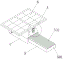
FIG. 2 is a schematic structural view of a power storage base according to the present invention;
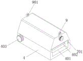
FIG. 3 is a schematic structural view of a mounting base according to the present invention;
FIG. 4 is an enlarged schematic view of the structure of FIG. 2 at A in accordance with the present invention;
fig. 5 is a schematic diagram of the circuit connection of the present invention.
In the figure: the solar energy heat-dissipation light-emitting diode comprises 1 mounting column, 101 access sealing doors, 2 supporting rods, 3 electric storage bases, 4 mounting bases, 401 lamp panel mounting grooves, 402 ventilation tunnels, 403 heat-dissipation motors, 5LED lamp panels, 501 heat-dissipation sealing plates, 502 heat-dissipation fins, 6 solar cell panels, 601 driven gears, 7 dust cover main bodies, 701 dust cover main body joint grooves, 8 steering motors, 801 driving gears, 9 butt joint clamping blocks and 901 matching rings.
Detailed Description
The technical solutions in the embodiments of the present invention will be clearly and completely described below with reference to the drawings in the embodiments of the present invention, and it is obvious that the described embodiments are only a part of the embodiments of the present invention, and not all of the embodiments. All other embodiments, which can be derived by a person skilled in the art from the embodiments given herein without making any creative effort, shall fall within the protection scope of the present invention.
Unless otherwise indicated, all references to up, down, left, right, front, back, inner and outer directions herein are to be interpreted as referring to up, down, left, right, front, back, inner and outer directions in the drawings to which the invention is directed.
The invention provides a photovoltaic solar illuminating lamp with an electric power storage function, which comprises a mounting column 1 with a built-in storage battery, a supporting rod 2 and a storage base 3, wherein the storage battery is arranged in the mounting column;
the support rod 2 is of a hollow round tube structure, the bottom end of the support rod 2 is fixedly welded to the center of the upper end face of the mounting column 1, the top end of the support rod 2 is fixedly welded to the electricity storage base 3, and the electricity storage base 3 comprises a group of mounting bases 4 matched with the support rod 2 in a welding mode, LED lamp panels 5 mounted on the side faces of the mounting bases 4 and a group of solar cell panels 6 mounted above the mounting bases 4;
the LED lamp comprises a mounting base 4, wherein two sides of the mounting base 4 are constructed to be inclined surfaces, a lamp plate mounting groove 401 butted with an LED lamp plate 5 is formed in the side surface where the mounting base 4 is matched with the LED lamp plate 5, a group of heat dissipation sealing plates 501 are embedded above the LED lamp plate 5, a plurality of groups of heat dissipation fins 502 perpendicular to the heat dissipation sealing plates 501 are equidistantly constructed on the heat dissipation sealing plates 501, a group of ventilation tunnels 402 penetrating through the mounting base 4 is formed in the mounting base 4, one side of each ventilation tunnel 402 faces the heat dissipation fins 502 constructed on the heat dissipation sealing plates 501, one side of each ventilation tunnel 402, which is far away from the heat dissipation fins 502, is constructed to be a horn mouth, and a heat dissipation mechanism is;
butt joint fixture blocks 9 are constructed on two sides of the upper end face of the mounting base 4, a matching block structure of two groups of butt joint fixture blocks 9 on the set of butt joint mounting base 4 is constructed in the middle of the bottom end of the solar cell panel 6, connecting shafts of the butt joint fixture blocks 9 are arranged on two sides of the matching block, matching rings 901 matching the connecting shafts are arranged in the butt joint fixture blocks 9, the connecting shafts are matched with the adjusting mechanism, and the solar cell panel 6 rotates around the axis of the connecting shafts.
Specifically, a cabin for installing the storage battery and the electric control equipment is arranged in the installation column 1, a group of commercial power interfaces for connecting cables is arranged at the bottom end of the cabin, and the side face of the cabin is sealed by a group of maintenance sealing doors 101 which are matched with hinges in a hinged mode.
Specifically, the heat dissipation mechanism includes a set of heat dissipation motor 403 of the side-mounting of mounting base 4, the motor shaft of heat dissipation motor 403 docks with a set of wheeled fan of installing in mounting base 4, and wherein, wheeled fan is installed in the position that ventilation tunnel 402 structure is the horn mouth, is provided with heat dissipation shrouding 501 and heat radiation fins 502 that increase heat radiating area on the LED lamp plate 5, and heat radiation fins 502 mounted position docks with ventilation tunnel 402, when heat dissipation motor 403 drive wheeled fan was rotatory, can realize the induced air in ventilation tunnel 402.
Specifically, the adjustment mechanism of 6 bottom connecting axles of cooperation solar cell panel is a set of motor 8 that turns to, turn to motor 8 gomphosis placed in the middle and install the top of seting up lamp plate mounting groove 401 position in mounting base 4, and be provided with a set of driving gear 801 on turning to the motor shaft of motor 8, the driven gear 601 that has a set of meshing driving gear 801 on turning to the connecting axle of motor 8 mounted position one side towards, solar cell panel 6's angle can be adjusted by turning to motor 8, when driving gear 801 rotation meshing driven gear 601, solar cell panel 6 is rotatory around the axle center of connecting axle, realize the change of angle, adapt to different illumination angles.
Specifically, a set of dust cover main body butt joint grooves 701 for the embedding of the dust cover main body 7 are formed above the lamp panel mounting groove 401 of the mounting base 4, the folded plate structures are constructed on the two sides of the dust cover main body 7, and the dust cover main body 7 covers the heat dissipation fins 502 of the LED lamp panel 5.
Specifically, the two sides of the heat dissipation sealing plate 501 and the two sides of the LED lamp panel 5 close to the installation position of the heat dissipation sealing plate 501 are fixed by the clamping of the folded plate structures on the two sides of the dust cover main body 7, the air guide channel for communicating the ventilation tunnel 402 is surrounded by the gaps between the dust cover main body 7 and the multiple groups of heat dissipation fins 502, the dust cover main body 7 is covered on the heat dissipation fins 502, and the heat is effectively taken away by the air flow through the whole group of heat dissipation fins 502.
Specifically, the solar cell panel 6 is connected with the storage battery in the mounting column 1 through a group of wires passing through the support rod 2.
Specifically, the stranded conductor of connecting battery and mains interface is worn to be equipped with by the inner space of bracing piece 2, and the tip of stranded conductor is connected with heat dissipation motor 403, LED lamp plate 5 and steering motor 8 respectively, and solar cell panel 6 can be saved solar energy in the battery of installation in erection column 1, and battery and mains interface are heat dissipation motor 403, LED lamp plate 5 and steering motor 8 power supply, guarantee the use when battery electric quantity is sufficient, and the access of commercial power when not enough with the electric quantity.
The photovoltaic solar illuminating lamp with the power storage function can realize automatic control over a steering motor 8 by combining an internet of things and a single chip microcomputer during daily use, ensures that when the steering motor 8 drives a driving gear 801 to be meshed with a driven gear 601, a solar cell panel 6 rotates around a connecting shaft to adapt to the illumination angle of the sun, heat generated by the LED lamp panel 5 during working is taken away by airflow introduced by a wheel type fan, a heat dissipation motor 403 drives the wheel type fan, and can realize air induction in a ventilation roadway 402, and effectively ensures that the airflow takes away the heat through the whole set of heat dissipation fins 502 by matching with a dust cover main body 7 which is covered above the heat dissipation fins 502, the heat dissipation efficiency is improved, the service life of the LED lamp panel 5 is ensured, the heat dissipation motor 403, the LED lamp panel 5 and the steering motor 8 are provided with two sets of power supplies which are respectively a storage battery and a mains supply interface, so as, guarantee daily result of use, this photovoltaic solar lamp with electric power storage function, the environmental protection is reliable, easily realizes the heat dissipation to the lamp plate to be convenient for adjust solar cell panel angle adaptation sun illumination, the practicality is strong.
Finally, it should be noted that: although the present invention has been described in detail with reference to the foregoing embodiments, it will be apparent to those skilled in the art that modifications may be made to the embodiments or portions thereof without departing from the spirit and scope of the invention.
Claims (8)
1. A photovoltaic solar illuminating lamp with an electric power storage function comprises a mounting column (1) with a built-in storage battery, a supporting rod (2) and a storage base (3);
the method is characterized in that: the support rod (2) is of a hollow round tube structure, the bottom end of the support rod (2) is fixedly welded to the center of the upper end face of the mounting column (1), the top end of the support rod (2) is fixedly welded to the electricity storage base (3), and the electricity storage base (3) comprises a group of mounting bases (4) matched with the support rod (2) in a welding mode, LED lamp panels (5) installed on the side faces of the mounting bases (4) and a group of solar cell panels (6) installed above the mounting bases (4);
the LED lamp comprises a mounting base (4), wherein two sides of the mounting base (4) are constructed to be inclined surfaces, a lamp plate mounting groove (401) which is connected with an LED lamp plate (5) in a butt joint mode is formed in the side face where the mounting base (4) is matched with the LED lamp plate (5) for mounting, a group of heat dissipation sealing plates (501) are embedded above the LED lamp plate (5), a plurality of groups of heat dissipation fins (502) which are perpendicular to the heat dissipation sealing plates (501) are equidistantly constructed on the heat dissipation sealing plates (501), a group of ventilation tunnels (402) which penetrate through the mounting base (4) are formed in the mounting base (4), one side of each ventilation tunnel (402) faces to the heat dissipation fins (502) which are constructed on the heat dissipation sealing plates (501), one side, far away from the heat dissipation fins (502), of each ventilation tunnel (402) is;
the utility model discloses a solar cell panel, including mounting base (4), mounting base (4) and solar cell panel, the up end both sides of mounting base (4) are constructed butt joint fixture block (9), the bottom of solar cell panel (6) is constructed between two parties and is had the cooperation piece structure of two sets of butt joint fixture block (9) on a set of butt joint mounting base (4), and wherein, the both sides of cooperation piece are provided with the connecting axle of butt joint fixture block (9), be provided with cooperation ring (901) of cooperation connecting axle in butt joint fixture block (9), and the connecting axle cooperates with adjustment mechanism, solar cell panel (6) are rotatory around the axle.
2. The photovoltaic solar illuminating lamp with the power storage function as claimed in claim 1, wherein: the electric control cabinet is characterized in that a cabin for installing the storage battery and the electric control equipment is arranged in the installation column (1), a group of commercial power interfaces connected with cables is arranged at the bottom end of the cabin, and the side face of the cabin is sealed by a group of maintenance sealing doors (101) matched and hinged with hinges.
3. The photovoltaic solar illuminating lamp with the power storage function as claimed in claim 1, wherein: the heat dissipation mechanism comprises a set of heat dissipation motors (403) arranged on the side face of the mounting base (4), motor shafts of the heat dissipation motors (403) are in butt joint with a set of wheel type fans arranged in the mounting base (4), and the wheel type fans are arranged at positions of a ventilation roadway (402) which are in a horn mouth structure.
4. The photovoltaic solar illuminating lamp with the power storage function as claimed in claim 1, wherein: the adjustment mechanism who cooperates solar cell panel (6) bottom connecting axle is a set of motor (8) that turns to, turn to motor (8) gomphosis installed between two parties and offer the top of lamp plate mounting groove (401) position in mounting base (4), and be provided with a set of driving gear (801) on the motor shaft that turns to motor (8), driven gear (601) that have a set of meshing driving gear (801) towards on the connecting axle that turns to motor (8) mounted position one side.
5. The photovoltaic solar illuminating lamp with the power storage function as claimed in claim 1, wherein: the LED lamp panel is characterized in that a set of dust cover main body butt joint grooves (701) for embedding the dust cover main body (7) are formed in the upper portion, where the lamp panel mounting groove (401) is formed, of the mounting base (4), the two sides of the dust cover main body (7) are constructed with folded plate structures, and the dust cover main body (7) covers and is connected above the heat dissipation fins (502) of the LED lamp panel (5).
6. The photovoltaic solar illuminating lamp with the power storage function as claimed in claim 5, wherein: the fixed heat dissipation shrouding (501) both sides of folded plate structure block and the both sides that LED lamp plate (5) are close to heat dissipation shrouding (501) mounted position of dust cover main part (7) both sides, the wind-guiding passageway that forms intercommunication ventilation tunnel (402) is enclosed in the gap between dust cover main part (7) and multiunit heat radiation fins (502).
7. The photovoltaic solar illuminating lamp with the power storage function as claimed in claim 1, wherein: the solar cell panel (6) is connected with the storage battery in the mounting column (1) through a group of wires penetrating through the support rod (2).
8. The photovoltaic solar illuminating lamp with the power storage function as claimed in claim 1, wherein: the inner space of bracing piece (2) wears to be equipped with the stranded conductor of connecting battery and commercial power interface, and the tip of stranded conductor is connected with heat dissipation motor (403), LED lamp plate (5) and steering motor (8) respectively.
Priority Applications (1)
| Application Number | Priority Date | Filing Date | Title |
|---|---|---|---|
| CN202010888316.4A CN111998295A (en) | 2020-08-28 | 2020-08-28 | Photovoltaic solar illuminating lamp with electric power storage function |
Applications Claiming Priority (1)
| Application Number | Priority Date | Filing Date | Title |
|---|---|---|---|
| CN202010888316.4A CN111998295A (en) | 2020-08-28 | 2020-08-28 | Photovoltaic solar illuminating lamp with electric power storage function |
Publications (1)
| Publication Number | Publication Date |
|---|---|
| CN111998295A true CN111998295A (en) | 2020-11-27 |
Family
ID=73464590
Family Applications (1)
| Application Number | Title | Priority Date | Filing Date |
|---|---|---|---|
| CN202010888316.4A Pending CN111998295A (en) | 2020-08-28 | 2020-08-28 | Photovoltaic solar illuminating lamp with electric power storage function |
Country Status (1)
| Country | Link |
|---|---|
| CN (1) | CN111998295A (en) |
Cited By (1)
| Publication number | Priority date | Publication date | Assignee | Title |
|---|---|---|---|---|
| CN114992568A (en) * | 2022-06-15 | 2022-09-02 | 江苏宜柯谷林能源科技有限公司 | Wind-solar complementary solar street lamp |
Citations (5)
| Publication number | Priority date | Publication date | Assignee | Title |
|---|---|---|---|---|
| CN206904930U (en) * | 2017-06-26 | 2018-01-19 | 深圳市必拓电子股份有限公司 | Bulkhead lamp |
| CN207350010U (en) * | 2017-06-26 | 2018-05-11 | 深圳市科鼎光电有限公司 | A kind of pavement environmental protection and energy saving LED light |
| CN108105728A (en) * | 2017-11-14 | 2018-06-01 | 成都瑞普欧光电有限公司 | The solar street lamp controller that can be rotated with sunray |
| CN109307204A (en) * | 2018-10-16 | 2019-02-05 | 众普森科技(株洲)有限公司 | Lamps and lanterns |
| CN210609007U (en) * | 2019-10-10 | 2020-05-22 | 青岛颐杰鸿利科技有限公司 | Solar power generation device with solar panel angle adjusting function |
-
2020
- 2020-08-28 CN CN202010888316.4A patent/CN111998295A/en active Pending
Patent Citations (5)
| Publication number | Priority date | Publication date | Assignee | Title |
|---|---|---|---|---|
| CN206904930U (en) * | 2017-06-26 | 2018-01-19 | 深圳市必拓电子股份有限公司 | Bulkhead lamp |
| CN207350010U (en) * | 2017-06-26 | 2018-05-11 | 深圳市科鼎光电有限公司 | A kind of pavement environmental protection and energy saving LED light |
| CN108105728A (en) * | 2017-11-14 | 2018-06-01 | 成都瑞普欧光电有限公司 | The solar street lamp controller that can be rotated with sunray |
| CN109307204A (en) * | 2018-10-16 | 2019-02-05 | 众普森科技(株洲)有限公司 | Lamps and lanterns |
| CN210609007U (en) * | 2019-10-10 | 2020-05-22 | 青岛颐杰鸿利科技有限公司 | Solar power generation device with solar panel angle adjusting function |
Cited By (1)
| Publication number | Priority date | Publication date | Assignee | Title |
|---|---|---|---|---|
| CN114992568A (en) * | 2022-06-15 | 2022-09-02 | 江苏宜柯谷林能源科技有限公司 | Wind-solar complementary solar street lamp |
Similar Documents
| Publication | Publication Date | Title |
|---|---|---|
| CN2586875Y (en) | Sunflower style solar energy road lamp | |
| CN2597824Y (en) | Solar LED street light installation | |
| CN109347427B (en) | A solar photovoltaic power generation and building sunshade integrated system and adjustment method | |
| CN214038197U (en) | Efficient solar street lamp | |
| CN205690267U (en) | Wind and solar energy LED street lamp | |
| CN211424160U (en) | Safe anti-theft auto-induction LED energy-saving lighting device | |
| CN113503509A (en) | Solar-powered municipal street lamp and mounting method thereof | |
| CN210424824U (en) | Solar street lamp convenient to installation | |
| CN214948712U (en) | Solar street lamp capable of tracking and capturing sunlight | |
| CN216383953U (en) | Solar street lamp | |
| CN216244016U (en) | A kind of direction adjustment device of solar light | |
| CN115031202B (en) | Street lamp power station | |
| CN211119259U (en) | Solar driving power supply for L ED lamp | |
| CN212273871U (en) | Solar intelligent control street lamp | |
| CN211716442U (en) | Solar street lamp is used in municipal administration | |
| CN211289849U (en) | Solar street lamp device | |
| CN211526298U (en) | Lifting type solar street lamp | |
| CN215951291U (en) | A smart photovoltaic street light | |
| CN222992818U (en) | But angle regulation's LED electricity-saving lamp | |
| CN113587030A (en) | Solar energy lighting lamp | |
| CN118959965B (en) | Solar street lamp capable of controlling light source change | |
| CN218064661U (en) | An intelligent lighting device powered by new energy | |
| CN220135268U (en) | Solar street lamp convenient to adjust | |
| CN111486401A (en) | Lithium electricity solar energy thing networking wisdom street lamp | |
| CN224175114U (en) | Protection type fish-like fin type bulb convenient for heat dissipation |
Legal Events
| Date | Code | Title | Description |
|---|---|---|---|
| PB01 | Publication | ||
| PB01 | Publication | ||
| SE01 | Entry into force of request for substantive examination | ||
| SE01 | Entry into force of request for substantive examination | ||
| RJ01 | Rejection of invention patent application after publication |
Application publication date: 20201127 |
|
| RJ01 | Rejection of invention patent application after publication |