CN111981945A - Tractor spring testing fixture - Google Patents
Tractor spring testing fixture Download PDFInfo
- Publication number
- CN111981945A CN111981945A CN202010819282.3A CN202010819282A CN111981945A CN 111981945 A CN111981945 A CN 111981945A CN 202010819282 A CN202010819282 A CN 202010819282A CN 111981945 A CN111981945 A CN 111981945A
- Authority
- CN
- China
- Prior art keywords
- fixed
- blocks
- base
- vertical plate
- block
- Prior art date
- Legal status (The legal status is an assumption and is not a legal conclusion. Google has not performed a legal analysis and makes no representation as to the accuracy of the status listed.)
- Withdrawn
Links
- 238000001514 detection method Methods 0.000 abstract description 6
- 238000007796 conventional method Methods 0.000 description 1
- 238000007689 inspection Methods 0.000 description 1
- 238000005259 measurement Methods 0.000 description 1
- 238000000034 method Methods 0.000 description 1
Images


Classifications
-
- G—PHYSICS
- G01—MEASURING; TESTING
- G01B—MEASURING LENGTH, THICKNESS OR SIMILAR LINEAR DIMENSIONS; MEASURING ANGLES; MEASURING AREAS; MEASURING IRREGULARITIES OF SURFACES OR CONTOURS
- G01B5/00—Measuring arrangements characterised by the use of mechanical techniques
- G01B5/02—Measuring arrangements characterised by the use of mechanical techniques for measuring length, width or thickness
- G01B5/06—Measuring arrangements characterised by the use of mechanical techniques for measuring length, width or thickness for measuring thickness
- G01B5/061—Measuring arrangements characterised by the use of mechanical techniques for measuring length, width or thickness for measuring thickness height gauges
-
- G—PHYSICS
- G01—MEASURING; TESTING
- G01B—MEASURING LENGTH, THICKNESS OR SIMILAR LINEAR DIMENSIONS; MEASURING ANGLES; MEASURING AREAS; MEASURING IRREGULARITIES OF SURFACES OR CONTOURS
- G01B5/00—Measuring arrangements characterised by the use of mechanical techniques
- G01B5/0025—Measuring of vehicle parts
-
- G—PHYSICS
- G01—MEASURING; TESTING
- G01B—MEASURING LENGTH, THICKNESS OR SIMILAR LINEAR DIMENSIONS; MEASURING ANGLES; MEASURING AREAS; MEASURING IRREGULARITIES OF SURFACES OR CONTOURS
- G01B5/00—Measuring arrangements characterised by the use of mechanical techniques
- G01B5/02—Measuring arrangements characterised by the use of mechanical techniques for measuring length, width or thickness
-
- G—PHYSICS
- G01—MEASURING; TESTING
- G01B—MEASURING LENGTH, THICKNESS OR SIMILAR LINEAR DIMENSIONS; MEASURING ANGLES; MEASURING AREAS; MEASURING IRREGULARITIES OF SURFACES OR CONTOURS
- G01B5/00—Measuring arrangements characterised by the use of mechanical techniques
- G01B5/24—Measuring arrangements characterised by the use of mechanical techniques for measuring angles or tapers; for testing the alignment of axes
- G01B5/25—Measuring arrangements characterised by the use of mechanical techniques for measuring angles or tapers; for testing the alignment of axes for testing the alignment of axes
Landscapes
- Physics & Mathematics (AREA)
- General Physics & Mathematics (AREA)
- Length-Measuring Instruments Using Mechanical Means (AREA)
Abstract
Tractor spring examines utensil relates to the spring and examines the utensil field. The device is designed for solving the problem that the detection tool capable of simultaneously detecting the free arc height, the half-chord length and the symmetry degree of a central bolt of the tractor spring does not exist at present. The device comprises a bracket, wherein a bottom plate is fixed at the top of the bracket, a fixed end base block is arranged at the left part of the bottom plate, and a movable end base block is arranged at the right part of the bottom plate; the fixed end base block is provided with a V-shaped groove, and the fixed end base block and the movable end base block are both provided with bolts; the base is fixed in the middle of the bottom plate, the ruler base is fixed on the top of the base and provided with a front vertical plate and a rear vertical plate, and guide pillars on the fixing block are inserted into holes of the front vertical plate and the rear vertical plate; the convex block of the sliding block is inserted into the groove of the fixed block, the top of the fixed block is provided with a sliding sleeve, and the symmetry measuring ruler is arranged in the sliding sleeve. The sliding block is provided with a half-chord length measuring ruler slide rail, the half-chord length measuring ruler base is installed in a sliding fit mode with the half-chord length measuring ruler slide rail, and the half-chord length measuring ruler is fixed on the half-chord length measuring ruler base. The advantage is that can detect tractor spring free arc height, half string length, central bolt symmetry simultaneously.
Description
The technical field is as follows:
the invention relates to the field of spring detection tools, in particular to a detection tool capable of detecting the free arc height, the half-chord length and the symmetry degree of a central bolt of a tractor spring.
Background art:
the free arc height detection of the spring of the tractor is a necessary detection item, the conventional method generally adopts a ruler or a tape measure, the detection error is large, the precision is low, time and labor are wasted, and the labor intensity of workers is high; before, the half-chord length value and the central bolt symmetry degree of a tractor spring (namely whether the central bolt is on the longitudinal central line of a plate spring) are not detected, but at present, a plurality of users need to detect the half-chord length value and the central bolt symmetry degree, so that an inspection device capable of simultaneously detecting the free arc height, the half-chord length and the central bolt symmetry degree of the tractor spring is urgently needed to be designed, and the three indexes are detected, so that products leaving a factory can meet the user requirements.
The invention content is as follows:
the invention aims to solve the technical problem of providing a tractor spring gauge which can simultaneously detect the free arc height, the half-chord length and the central bolt symmetry degree of a tractor spring, and has the advantages of time and labor saving and high precision.
The above object is achieved by: the device comprises a bracket, wherein a bottom plate is fixed at the top of the bracket, two fixed end base blocks are fixed at the left part of the upper surface of the bottom plate, and two movable end base blocks are fixed at the right part of the upper surface of the bottom plate; the two fixed end base blocks and the two movable end base blocks are arranged in front and back;
the upper surfaces of the two fixed end base blocks are provided with V-shaped grooves extending downwards, threaded holes are formed in the two fixed end base blocks right below the V-shaped grooves, bolts are installed in the threaded holes, the heads of the two bolts are arranged on the outer sides of the two fixed end base blocks, the screw rods are exposed from the inner sides of the two fixed end base blocks, and the screw rod ends of the two bolts are opposite;
the two movable end base blocks are provided with threaded holes, the bolts are arranged in the threaded holes, the heads of the two bolts are arranged on the outer sides of the two fixed end base blocks, the screw rods are exposed out of the inner sides of the two fixed end base blocks, and the screw rod ends of the two bolts are opposite;
the base is fixed in the middle of the bottom plate, the ruler base is fixed at the top of the base, a front vertical plate extending upwards is fixed at the front end of the ruler base, a rear vertical plate extending upwards is fixed at the rear end of the ruler base, jackscrews are mounted in the middle of the front vertical plate and the rear vertical plate, holes are formed in the front vertical plate and the rear vertical plate on two sides of the jackscrew, fixed blocks are arranged above the front vertical plate and the rear vertical plate, guide posts are respectively fixed on the lower surfaces of the two fixed blocks at positions corresponding to the holes in the front vertical plate and the rear vertical plate, and the guide posts on the two fixed blocks are respectively inserted into;
the upper surfaces of the two fixed blocks are provided with concave grooves, a sliding block is arranged above each fixed block, the lower surfaces of the two sliding blocks are respectively fixed with a convex block, the convex blocks of the two sliding blocks are respectively inserted into the grooves of the two fixed blocks, sliding sleeves arranged in the front-back direction are fixed at the tops of the two fixed blocks, the two symmetry measuring rulers are respectively arranged in the sliding sleeves at the tops of the two fixed blocks, and the two symmetry measuring rulers are respectively in sliding contact with the two sliding sleeves. The two symmetry measuring rulers are arranged along the Y-axis direction. The fixed block located on the rear side is provided with scales transversely arranged, wherein the scale 0 is located in the middle of the fixed block.
One end of the upper surface of the sliding block positioned at the front side is fixed with a half-chord length measuring ruler slide rail, a half-chord length measuring ruler base is installed with the half-chord length measuring ruler slide rail in a sliding fit mode, and the half-chord length measuring ruler is fixed on the half-chord length measuring ruler base. The half-chord length measuring ruler base is perpendicular to the sliding block, namely the half-chord length measuring ruler is arranged in the X-axis direction.
The middle part of the bottom plate is also fixedly provided with two shaft sliding rails, an X shaft sliding rail of the two shaft sliding rails is fixed on the bottom plate, a Y shaft sliding rail can slide left and right on the X shaft sliding rail, the arc height ruler seat is fixed on the Y shaft sliding rail, the lower end of the ruler body of the digital display vernier caliper for measuring the arc height is fixed on the arc height ruler seat, and the vernier end part of the digital display vernier caliper is fixedly provided with a sleeve.
The measuring method comprises the following steps: during measurement, mandrels are installed in holes at the left end and the right end of a workpiece, the mandrel at the left end of the workpiece is arranged in a V-shaped groove of the fixed end base block, and the mandrel at the right end of the workpiece is arranged on the movable end base block. And sleeving a temporary sleeve on the central bolt of the workpiece.
Firstly, when measuring the symmetry degree of a central bolt, aligning two symmetry measuring rulers to the central bolt of a workpiece, screwing bolts on a fixed end base block and a movable end base block which are positioned on the rear side, so that the front side surface of the workpiece is attached to the fixed end base block and the movable end base block which are positioned on the front side, recording a numerical value a from a temporary sleeve through the symmetry measuring ruler which is positioned on the rear side, then screwing bolts on the fixed end base block and the movable base block which are positioned on the front side, so that the rear side surface of the workpiece is attached to the fixed end base block and the movable end base block which are positioned on the rear side, and recording a numerical value b from the temporary sleeve through the symmetry measuring ruler which is positioned on the front side, wherein (a-b)/2 is the symmetry numerical value.
Secondly, measuring the length of the half chord: the linear distance from the left edge of the base to the center of the V-shaped groove (namely the center of the spring eye of the plate spring) of the fixed end base block is a fixed value c, the sliding block in front of the workpiece and the base of the half-chord length measuring ruler are moved, the middle point of the sliding block is aligned with the scale 0 of the fixed block, the distance between the left edge of the temporary sleeve outside the central bolt and the left edge of the base is measured by the half-chord length measuring ruler at the moment and is d, the radius of the sleeve is r, and then c + d + r is the.
And thirdly, measuring the arc height, and adjusting the position of the digital vernier caliper to enable the sleeve to be sleeved on the central bolt, wherein the reading of the digital vernier caliper is the arc height.
The invention has the advantages that: can detect tractor spring free arc height, half string length, central bolt symmetry simultaneously, detect labour saving and time saving, the precision is high.
Description of the drawings:
FIG. 1 is a schematic structural view of the present invention;
FIG. 2 is a schematic view of the structure of the fixed end block of the present invention;
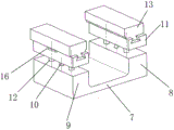
FIG. 3 is a schematic view showing the connection state of the ruler base, the fixed block and the sliding block.
The specific implementation mode is as follows:
the invention is further illustrated with reference to fig. 1-3;
the device comprises a bracket 1, a bottom plate 2 is fixed on the top of the bracket, two fixed end base blocks 3 are fixed on the left part of the upper surface of the bottom plate, and two movable end base blocks 4 are fixed on the right part of the upper surface of the bottom plate; the two fixed end base blocks and the two movable end base blocks are arranged in front and back;
the upper surfaces of the two fixed end base blocks are provided with V-shaped grooves 5 extending downwards, threaded holes are formed in the two fixed end base blocks right below the V-shaped grooves, bolts are installed in the threaded holes, the heads of the two bolts are arranged on the outer sides of the two fixed end base blocks, the screw rods are exposed from the inner sides of the two fixed end base blocks, and the screw rod ends of the two bolts are opposite;
the two movable end base blocks are provided with threaded holes, the bolts are arranged in the threaded holes, the heads of the two bolts are arranged on the outer sides of the two fixed end base blocks, the screw rods are exposed out of the inner sides of the two fixed end base blocks, and the screw rod ends of the two bolts are opposite;
the base 6 is fixed in the middle of the bottom plate, the ruler base 7 is fixed on the top of the base, a front vertical plate 8 extending upwards is fixed at the front end of the ruler base, a rear vertical plate 9 extending upwards is fixed at the rear end of the ruler base, jackscrews 10 are installed in the middle of the front vertical plate and the rear vertical plate, holes are formed in the front vertical plate and the rear vertical plate on two sides of the jackscrews, fixed blocks 11 are arranged above the front vertical plate and the rear vertical plate, guide pillars 12 are respectively fixed on the lower surfaces of the two fixed blocks at positions corresponding to the holes in the front vertical plate and the rear vertical plate, and the guide pillars on the two fixed blocks are respectively inserted into;
the upper surfaces of the two fixed blocks are provided with concave grooves, a sliding block 13 is arranged above each fixed block, the lower surfaces of the two sliding blocks are respectively fixed with a convex block, the convex blocks of the two sliding blocks are respectively inserted into the grooves of the two fixed blocks, sliding sleeves 14 arranged in the front-back direction are respectively fixed at the tops of the two fixed blocks, two symmetry measuring rulers 15 are respectively arranged in the sliding sleeves at the tops of the two fixed blocks, and the two symmetry measuring rulers are respectively in sliding contact with the two sliding sleeves. The two symmetry measuring rulers are arranged along the Y-axis direction. The fixed block at the rear side is provided with a scale 16 which is transversely arranged, wherein the scale 0 is positioned in the middle of the fixed block.
One end of the upper surface of the sliding block positioned at the front side is fixed with a half-chord length measuring ruler slide rail 17, a half-chord length measuring ruler base 18 is installed in a sliding fit with the half-chord length measuring ruler slide rail, and a half-chord length measuring ruler 19 is fixed on the half-chord length measuring ruler base. The half-chord length measuring ruler base is perpendicular to the sliding block, namely the half-chord length measuring ruler is arranged in the X-axis direction.
The middle part of the bottom plate is also fixed with a two-axis slide rail 20, the X-axis slide rail of the two-axis slide rail is fixed on the bottom plate, the Y-axis slide rail can slide left and right on the X-axis slide rail, the arc height ruler seat 21 is fixed on the Y-axis slide rail, the lower end of the ruler body of the digital display vernier caliper 22 for measuring the arc height is fixed on the arc height ruler seat, and the vernier end part of the digital display vernier caliper is fixed with a sleeve 23.
Claims (2)
1. Tractor spring examines utensil, including support (1), bottom plate (2) are fixed at the top of support, characterized by: two fixed end base blocks (3) are fixed at the left part of the upper surface of the bottom plate, and two movable end base blocks (4) are fixed at the right part of the upper surface of the bottom plate; the two fixed end base blocks and the two movable end base blocks are arranged in front and back;
the upper surfaces of the two fixed end base blocks are provided with V-shaped grooves (5) extending downwards, threaded holes are formed in the two fixed end base blocks right below the V-shaped grooves, bolts are installed in the threaded holes, the heads of the two bolts are arranged on the outer sides of the two fixed end base blocks, the screw rods are exposed from the inner sides of the two fixed end base blocks, and the screw rod ends of the two bolts are opposite;
the two movable end base blocks are provided with threaded holes, the bolts are arranged in the threaded holes, the heads of the two bolts are arranged on the outer sides of the two fixed end base blocks, the screw rods are exposed out of the inner sides of the two fixed end base blocks, and the screw rod ends of the two bolts are opposite;
the base (6) is fixed in the middle of the bottom plate, the ruler base (7) is fixed at the top of the base, a front vertical plate (8) extending upwards is fixed at the front end of the ruler base, a rear vertical plate (9) extending upwards is fixed at the rear end of the ruler base, jackscrews (10) are mounted in the middle of the front vertical plate and the rear vertical plate, holes are formed in the front vertical plate and the rear vertical plate on two sides of the jackscrew, fixing blocks (11) are arranged above the front vertical plate and the rear vertical plate, guide pillars (12) are respectively fixed on the lower surfaces of the two fixing blocks at positions corresponding to the holes in the front vertical plate and the rear vertical plate, and the guide pillars on the two fixing;
the upper surfaces of the two fixed blocks are provided with concave grooves, a sliding block (13) is arranged above each fixed block, the lower surfaces of the two sliding blocks are respectively fixed with a convex block, the convex blocks of the two sliding blocks are respectively inserted into the grooves of the two fixed blocks, the tops of the two fixed blocks are respectively fixed with sliding sleeves (14) arranged in the front-back direction, two symmetry measuring rulers (15) are respectively arranged in the sliding sleeves at the tops of the two fixed blocks, and the two symmetry measuring rulers are respectively in sliding contact with the two sliding sleeves; the two symmetry measuring rulers are arranged along the Y-axis direction; the fixed block positioned at the rear side is provided with a scale (16) which is transversely arranged, wherein the scale 0 is positioned in the middle of the fixed block;
one end of the upper surface of the sliding block positioned at the front side is fixed with a half-chord length measuring ruler slide rail (17), a half-chord length measuring ruler base (18) is installed with the half-chord length measuring ruler slide rail in a sliding fit mode, a half-chord length measuring ruler (19) is fixed on the half-chord length measuring ruler base, and the half-chord length measuring ruler base is perpendicular to the sliding block, namely the half-chord length measuring ruler is arranged in the X-axis direction.
2. The tractor spring test tool of claim 1, wherein: the middle part of the bottom plate is also fixedly provided with a two-axis slide rail (20), an X-axis slide rail of the two-axis slide rail is fixed on the bottom plate, a Y-axis slide rail can slide left and right on the X-axis slide rail, an arc height ruler seat (21) is fixed on the Y-axis slide rail, the lower end of a ruler body of a digital display vernier caliper (22) for measuring the arc height is fixed on the arc height ruler seat, and the vernier end part of the digital display vernier caliper is fixedly provided with a sleeve (23).
Priority Applications (1)
| Application Number | Priority Date | Filing Date | Title |
|---|---|---|---|
| CN202010819282.3A CN111981945A (en) | 2020-08-14 | 2020-08-14 | Tractor spring testing fixture |
Applications Claiming Priority (1)
| Application Number | Priority Date | Filing Date | Title |
|---|---|---|---|
| CN202010819282.3A CN111981945A (en) | 2020-08-14 | 2020-08-14 | Tractor spring testing fixture |
Publications (1)
| Publication Number | Publication Date |
|---|---|
| CN111981945A true CN111981945A (en) | 2020-11-24 |
Family
ID=73435500
Family Applications (1)
| Application Number | Title | Priority Date | Filing Date |
|---|---|---|---|
| CN202010819282.3A Withdrawn CN111981945A (en) | 2020-08-14 | 2020-08-14 | Tractor spring testing fixture |
Country Status (1)
| Country | Link |
|---|---|
| CN (1) | CN111981945A (en) |
Cited By (1)
| Publication number | Priority date | Publication date | Assignee | Title |
|---|---|---|---|---|
| CN119533365A (en) * | 2025-01-22 | 2025-02-28 | 山东汽车弹簧厂淄博有限公司 | Automatic detection device and method for half chord length of leaf spring under set load |
Citations (6)
| Publication number | Priority date | Publication date | Assignee | Title |
|---|---|---|---|---|
| KR20120001097A (en) * | 2010-06-29 | 2012-01-04 | 대원강업주식회사 | Outer diameter and effective number measuring device for coil spring |
| KR101382142B1 (en) * | 2012-10-26 | 2014-04-08 | 한국해양과학기술원 | Manual spring stiffness measuring device |
| CN206339176U (en) * | 2016-12-21 | 2017-07-18 | 浙江宏业检测科技有限公司 | A kind of reinforcing bar length-measuring appliance |
| CN107478134A (en) * | 2017-08-21 | 2017-12-15 | 爱姆捷汽车零部件(安徽)有限公司 | A kind of piston lever of reducer for automobile external diameter linearity testing apparatus |
| CN209588895U (en) * | 2019-04-26 | 2019-11-05 | 北京新能源汽车股份有限公司 | Front windshield detection and adjustment device and vehicle body main inspection device |
| CN211121021U (en) * | 2020-01-09 | 2020-07-28 | 瑞卡斯(南京)精密机械有限公司 | A three-coordinate detection device for the symmetry of the keyway of the transmission shaft |
-
2020
- 2020-08-14 CN CN202010819282.3A patent/CN111981945A/en not_active Withdrawn
Patent Citations (6)
| Publication number | Priority date | Publication date | Assignee | Title |
|---|---|---|---|---|
| KR20120001097A (en) * | 2010-06-29 | 2012-01-04 | 대원강업주식회사 | Outer diameter and effective number measuring device for coil spring |
| KR101382142B1 (en) * | 2012-10-26 | 2014-04-08 | 한국해양과학기술원 | Manual spring stiffness measuring device |
| CN206339176U (en) * | 2016-12-21 | 2017-07-18 | 浙江宏业检测科技有限公司 | A kind of reinforcing bar length-measuring appliance |
| CN107478134A (en) * | 2017-08-21 | 2017-12-15 | 爱姆捷汽车零部件(安徽)有限公司 | A kind of piston lever of reducer for automobile external diameter linearity testing apparatus |
| CN209588895U (en) * | 2019-04-26 | 2019-11-05 | 北京新能源汽车股份有限公司 | Front windshield detection and adjustment device and vehicle body main inspection device |
| CN211121021U (en) * | 2020-01-09 | 2020-07-28 | 瑞卡斯(南京)精密机械有限公司 | A three-coordinate detection device for the symmetry of the keyway of the transmission shaft |
Non-Patent Citations (1)
| Title |
|---|
| 赵煜 等: "浅谈商用车钢板弹簧配对检具设计与制造", 《机电信息》 * |
Cited By (1)
| Publication number | Priority date | Publication date | Assignee | Title |
|---|---|---|---|---|
| CN119533365A (en) * | 2025-01-22 | 2025-02-28 | 山东汽车弹簧厂淄博有限公司 | Automatic detection device and method for half chord length of leaf spring under set load |
Similar Documents
| Publication | Publication Date | Title |
|---|---|---|
| CN106017259A (en) | Apparatus for measuring linearity of elevator guide rail and measuring method thereof | |
| CN212512833U (en) | Thickness measuring device for dial gauge at any point position | |
| CN104501695B (en) | Seam allowance size measuring instrument of chain link | |
| CN107436120B (en) | Flexible gauge and method for detecting installation size of side end face of gauge baffle | |
| CN108592851B (en) | Workpiece symmetry detection tool and detection method | |
| CN219736246U (en) | Planer-type flatness detects frock | |
| CN203744873U (en) | Center line gauge | |
| CN214792948U (en) | Two-hole parallelism measuring and detecting tool | |
| CN201355239Y (en) | Check tool surface error measuring instrument | |
| CN215930767U (en) | Measuring and checking tool for processing hole type groove depth of roll collar | |
| CN212458206U (en) | Internal thread pitch diameter detection device | |
| CN110440668B (en) | Measuring device for bearing ring channel position | |
| CN220083891U (en) | Reinforcing bar diameter detection device | |
| CN208109067U (en) | The linearity measurer of upright bar | |
| CN216159790U (en) | A measuring tool for measuring the distance between the line rails of the machine tool bed | |
| CN216246003U (en) | Building engineering quality detection device | |
| CN206258054U (en) | A kind of cubing for detecting disk roller maximum outside diameter | |
| CN211668443U (en) | Measuring device based on grating ruler | |
| CN222652117U (en) | Segment size inspection device | |
| CN209512734U (en) | Novel detection device | |
| CN210374921U (en) | Marking coating thickness gauge | |
| CN109238105B (en) | Large-size inspection sample plate auxiliary tool for detecting surface curve of revolving body | |
| CN216482682U (en) | Device for rapidly detecting multiple height dimensions by utilizing dial gauge head | |
| CN115143864B (en) | Device and method for measuring slope and section steel leg thickness | |
| CN223091190U (en) | Welding inspection ruler inspection device |
Legal Events
| Date | Code | Title | Description |
|---|---|---|---|
| PB01 | Publication | ||
| PB01 | Publication | ||
| SE01 | Entry into force of request for substantive examination | ||
| SE01 | Entry into force of request for substantive examination | ||
| WW01 | Invention patent application withdrawn after publication |
Application publication date: 20201124 |
|
| WW01 | Invention patent application withdrawn after publication |