CN111962444A - A deep cleaning operation vehicle - Google Patents
A deep cleaning operation vehicle Download PDFInfo
- Publication number
- CN111962444A CN111962444A CN202010617211.5A CN202010617211A CN111962444A CN 111962444 A CN111962444 A CN 111962444A CN 202010617211 A CN202010617211 A CN 202010617211A CN 111962444 A CN111962444 A CN 111962444A
- Authority
- CN
- China
- Prior art keywords
- suction nozzle
- spray rod
- pressure water
- water pump
- rotary
- Prior art date
- Legal status (The legal status is an assumption and is not a legal conclusion. Google has not performed a legal analysis and makes no representation as to the accuracy of the status listed.)
- Pending
Links
Images


Classifications
-
- E—FIXED CONSTRUCTIONS
- E01—CONSTRUCTION OF ROADS, RAILWAYS, OR BRIDGES
- E01H—STREET CLEANING; CLEANING OF PERMANENT WAYS; CLEANING BEACHES; DISPERSING OR PREVENTING FOG IN GENERAL CLEANING STREET OR RAILWAY FURNITURE OR TUNNEL WALLS
- E01H1/00—Removing undesirable matter from roads or like surfaces, with or without moistening of the surface
- E01H1/10—Hydraulically loosening or dislodging undesirable matter; Raking or scraping apparatus ; Removing liquids or semi-liquids e.g., absorbing water, sliding-off mud
- E01H1/101—Hydraulic loosening or dislodging, combined or not with mechanical loosening or dislodging, e.g. road washing machines with brushes or wipers
-
- E—FIXED CONSTRUCTIONS
- E01—CONSTRUCTION OF ROADS, RAILWAYS, OR BRIDGES
- E01H—STREET CLEANING; CLEANING OF PERMANENT WAYS; CLEANING BEACHES; DISPERSING OR PREVENTING FOG IN GENERAL CLEANING STREET OR RAILWAY FURNITURE OR TUNNEL WALLS
- E01H1/00—Removing undesirable matter from roads or like surfaces, with or without moistening of the surface
- E01H1/08—Pneumatically dislodging or taking-up undesirable matter or small objects; Drying by heat only or by streams of gas; Cleaning by projecting abrasive particles
- E01H1/0863—Apparatus loosening or removing the dirt by blowing and subsequently dislodging it at least partially by suction ; Combined suction and blowing nozzles
- E01H1/0872—Apparatus loosening or removing the dirt by blowing and subsequently dislodging it at least partially by suction ; Combined suction and blowing nozzles with mechanical loosening or feeding instruments for the dirt to be removed pneumatically, e.g. brushes, scrapers
Landscapes
- Engineering & Computer Science (AREA)
- Architecture (AREA)
- Civil Engineering (AREA)
- Structural Engineering (AREA)
- Cleaning Of Streets, Tracks, Or Beaches (AREA)
Abstract
本发明公开了一种深度清洁作业车,其通过取力器从底盘上的变速箱取力驱动变量柱塞泵工作,进而驱动第一高压水泵旋转,有效利用了底盘发动机的资源,而第二高压水泵和风机所需功率则由副发动机承担,从而通过合理分配动力满足了深度清洁功能所需的大功率要求,既可以进行高油耗的深度除污作业,又可以进行传统洗扫车的普通清洁作业,可以满足不同工况需求,功能多样,最大程度提高了车辆的使用效率,并且底盘改动小、风险低,只需在传统洗扫车的基础上简单改装即可实现深度清洁作业功能,改装成本低。
The invention discloses a deep cleaning operation vehicle, which takes power from a gearbox on a chassis through a power take-off to drive a variable displacement plunger pump to work, and then drives a first high-pressure water pump to rotate, effectively utilizing the resources of the chassis engine, and the second The power required by the high-pressure water pump and fan is borne by the auxiliary engine, which can meet the high-power requirements of the deep cleaning function through reasonable distribution of power, which can not only carry out deep decontamination operations with high fuel consumption, but also carry out the ordinary cleaning of traditional vehicles. The cleaning operation can meet the needs of different working conditions, and has various functions, which maximizes the efficiency of the vehicle, and the chassis changes are small and the risk is low. Only a simple modification on the basis of the traditional cleaning vehicle can realize the deep cleaning operation function. Low cost of modification.
Description
技术领域technical field
本发明涉及道路污染深度清洁技术领域,特别地,涉及一种深度清洁作业车。The present invention relates to the technical field of deep cleaning of road pollution, in particular, to a deep cleaning operation vehicle.
背景技术Background technique
随着环卫作业装备的进步,我国城镇道路已经基本实现机械化清扫作业,洗扫车、清扫车和洒水车等环卫设备在城市道路保洁作业中被广泛使用。现有的传统洗扫车清洗水压力低,仅能清理道路表面的沙砾和粉尘,对于道路积垢、板结和油污等污染物无法进行有效清除,尤其在污染严重的城郊道路,单纯依靠洗扫车作业已无法满足要求,为解决城郊道路的污染问题,从源头上遏制道路扬尘,目前主要依靠洗扫车、清扫车和洒水车等多种设备重复作业的方式进行清理,不仅设备投入量大,效率低,综合成本高,而且作业效果无法得到保证。With the advancement of sanitation equipment, my country's urban roads have basically achieved mechanized cleaning operations, and sanitation equipment such as sweepers, sweepers and sprinklers are widely used in urban road cleaning operations. The existing traditional vehicle cleaning water pressure is low, and it can only clean the gravel and dust on the road surface. It cannot effectively remove pollutants such as road fouling, hardening and oil pollution, especially in the heavily polluted suburban roads, relying solely on cleaning Vehicle operation can no longer meet the requirements. In order to solve the pollution problem of suburban roads and curb road dust from the source, it mainly relies on repeated operations of various equipment such as sweepers, sweepers and sprinklers for cleaning, which not only requires a large amount of equipment investment. , the efficiency is low, the comprehensive cost is high, and the operation effect cannot be guaranteed.
对于道路积垢、板结、油污和污染严重的城郊道路,需要利用超高压力清洗水和低速行驶速度才能实现有效清洗,现有的道路污染清除车采用被动旋转式高压清洗装置,利用超高压力水的反冲力推动旋转接头及相连喷水杆旋转作业反复清洗路面,行走则采用液压驱动实现低速行走。具体地,如图1和图2所示,现有的道路污染清除车主要由底盘、分动箱、水箱、风机、垃圾箱、高压水泵、被动式旋转清洗装置和液压系统等组成,在底盘上加装分动箱,通过在分动箱上安装液压油泵,分别驱动与风机和高压水泵相连的液压马达旋转使之工作,风机抽走垃圾箱和吸嘴内的空气,垃圾箱和吸嘴内形成负压,高压水泵旋转产生高压水流,利用高压力水的反冲力推动被动式旋转清洗装置旋转作业反复清洗路面,底盘采用液压驱动实现低速行走,垃圾进入吸嘴内腔,在负压作用下被抽吸至垃圾箱,垃圾经过垃圾箱的沉降和过滤后留在垃圾箱内,较干净的气流进入风机后排出。For suburban roads with serious road fouling, hardening, oil and pollution, it is necessary to use ultra-high pressure washing water and low speed to achieve effective cleaning. The existing road pollution removal vehicles use passive rotary high-pressure cleaning devices, using ultra-high pressure The recoil force of the water drives the rotary joint and the connected water spray rod to rotate to clean the road repeatedly, and the hydraulic drive is used to realize low-speed walking. Specifically, as shown in Figures 1 and 2, the existing road pollution removal vehicle is mainly composed of a chassis, a transfer case, a water tank, a fan, a garbage can, a high-pressure water pump, a passive rotary cleaning device and a hydraulic system. Install a transfer case, install a hydraulic oil pump on the transfer case, and drive the hydraulic motors connected to the fan and the high-pressure water pump to rotate to make them work. The negative pressure is formed, the high-pressure water pump rotates to generate high-pressure water flow, and the recoil of the high-pressure water is used to drive the passive rotary cleaning device to rotate and clean the road repeatedly. It is sucked to the garbage bin, and the garbage remains in the garbage bin after being settled and filtered by the garbage bin, and the cleaner airflow enters the fan and is discharged.
但是,现有的道路污染清除车存在以下缺点:However, the existing road pollution removal vehicles have the following disadvantages:
1)结构复杂,成本高,风险大。整车采用单发传动系统,通过底盘加装分动箱取力,作业时上装风机、水泵和底盘行走都由液压马达驱动工作,以满足作业功率和低速行走需求。液压传动本身效率低,故障率高,且对底盘传动结构进行改制,影响了行驶安全。1) The structure is complex, the cost is high, and the risk is high. The whole vehicle adopts a single-engine transmission system, and a transfer case is installed on the chassis to take power. During operation, the upper fan, water pump and chassis walking are all driven by hydraulic motors to meet the needs of operating power and low-speed walking. The hydraulic transmission itself has low efficiency and high failure rate, and the chassis transmission structure is restructured, which affects the driving safety.
2)被动旋转式高压清洗装置转速不稳定,其转速与喷嘴射流角度、旋转阻力、喷嘴性能、作业速度等因素有关,一致性差,清洗效果不理想。2) The rotational speed of the passive rotary high-pressure cleaning device is unstable, and its rotational speed is related to the nozzle jet angle, rotational resistance, nozzle performance, operating speed and other factors, the consistency is poor, and the cleaning effect is not ideal.
3)功能单一,作为一款道路污染清除车,其主要功能是进行道路除污,但是油耗高,不适合城市道路保洁作业,造成资源浪费。3) It has a single function. As a road pollution removal vehicle, its main function is to decontaminate the road, but the fuel consumption is high, which is not suitable for urban road cleaning operations, resulting in waste of resources.
发明内容SUMMARY OF THE INVENTION
本发明提供了一种深度清洁作业车,以解决目前的道路污染清除车若需满足深度清洁要求需要在底盘上加装分动箱进行取力,从而导致结构复杂、成本高、风险大的技术问题。The invention provides a deep cleaning operation vehicle, so as to solve the technical problem that if the current road pollution removal vehicle needs to meet the deep cleaning requirements, a transfer case needs to be installed on the chassis to take power, resulting in complicated structure, high cost and high risk. question.
根据本发明的一个方面,提供一种深度清洁作业车,包括底盘、清水箱、副发动机、风机、变速箱、取力器、变量柱塞泵、柱塞马达、第一高压水泵、第二高压水泵、垃圾箱和吸嘴组件,所述副发动机、风机、变速箱、第一高压水泵、第二高压水泵、垃圾箱、吸嘴组件均安装在底盘上,所述第一高压水泵和第二高压水泵均与清水箱连接,所述取力器与变速箱连接以从底盘发动机取力,所述变量柱塞泵安装在取力器上,所述柱塞马达安装在第一高压水泵上,所述变量柱塞泵用于驱动柱塞马达旋转,从而带动第一高压水泵旋转输出高压水流,所述副发动机用于带动第二高压水泵和风机旋转,所述垃圾箱分别与风机、吸嘴组件连接,所述风机旋转后在垃圾箱和吸嘴组件内产生负压以对路面的垃圾进行吸拾,所述吸嘴组件上设置有多个喷水装置,所述第一高压水泵和第二高压水泵输出的高压水流经所述吸嘴组件上的至少一个喷水装置喷出以对路面进行清洗。According to one aspect of the present invention, a deep cleaning work vehicle is provided, including a chassis, a clean water tank, an auxiliary engine, a fan, a gearbox, a power take-off, a variable displacement plunger pump, a plunger motor, a first high-pressure water pump, a second high-pressure water pump Water pump, garbage can and suction nozzle assembly, the auxiliary engine, fan, gearbox, first high-pressure water pump, second high-pressure water pump, garbage can and suction nozzle assembly are all installed on the chassis, the first high-pressure water pump and the second high-pressure water pump The high-pressure water pumps are all connected to the clean water tank, the power take-off is connected to the gearbox to take power from the chassis engine, the variable displacement plunger pump is mounted on the power take-off, the plunger motor is mounted on the first high-pressure water pump, The variable displacement plunger pump is used to drive the plunger motor to rotate, thereby driving the first high-pressure water pump to rotate and output high-pressure water flow, and the auxiliary engine is used to drive the second high-pressure water pump and the fan to rotate. After the fan is rotated, a negative pressure is generated in the garbage bin and the suction nozzle assembly to pick up the garbage on the road. The suction nozzle assembly is provided with a plurality of water spraying devices, the first high-pressure water pump and the second high-pressure water pump The high-pressure water output by the two high-pressure water pumps flows through at least one water spray device on the suction nozzle assembly to be sprayed to clean the road surface.
进一步地,还包括水路控制阀块,所述水路控制阀块分别通过管路与第一高压水泵、第二高压水泵、吸嘴组件的多个喷水装置连接,所述水路控制阀块用于控制吸嘴组件的多个喷水装置的管路通断。Further, it also includes a water circuit control valve block, which is connected to the first high-pressure water pump, the second high-pressure water pump, and a plurality of water spraying devices of the suction nozzle assembly through pipelines, and the water circuit control valve block is used for Control the on-off of the pipelines of the multiple water spray devices of the suction nozzle assembly.
进一步地,所述第一高压水泵和第二高压水泵的出口端均安装有单向阀。Further, a check valve is installed at the outlet ends of the first high-pressure water pump and the second high-pressure water pump.
进一步地,还包括安装在底盘上并位于吸嘴组件前方的扫盘组件,所述扫盘组件用于将路面垃圾清扫聚拢至吸嘴组件的前方。Further, it also includes a sweeping plate assembly mounted on the chassis and located in front of the suction nozzle assembly, the sweeping plate assembly is used to sweep and gather road debris to the front of the suction nozzle assembly.
进一步地,所述吸嘴组件包括吸嘴体和主动旋转型高压射流清洁装置,所述吸嘴体固定安装在底盘上,所述吸嘴体上设置有与垃圾箱连接的吸嘴口,所述主动旋转型高压射流清洁装置包括马达、张紧装置和旋转接头,所述马达、张紧装置和旋转接头均固定安装在吸嘴体上,所述马达通过皮带驱动与其相邻的两个旋转接头转动,所述张紧装置用于支撑皮带,每个旋转接头上安装有多根均匀分布的旋转喷杆,每根旋转喷杆的末端安装有喷嘴,所述旋转接头通过管路与水路控制阀块连接,所述第一高压水泵和第二高压水泵输出的高压水流经旋转接头、旋转喷杆从喷嘴喷出,且旋转喷杆在马达的带动下转动以对路面进行主动旋转式高压冲洗。Further, the suction nozzle assembly includes a suction nozzle body and an active rotating high-pressure jet cleaning device, the suction nozzle body is fixedly installed on the chassis, and the suction nozzle body is provided with a suction nozzle port connected to the garbage box, so The active rotation type high-pressure jet cleaning device includes a motor, a tensioning device and a rotary joint. The motor, the tensioning device and the rotary joint are all fixedly installed on the suction nozzle body, and the motor drives the two adjacent rotations through a belt. The joint rotates, the tensioning device is used to support the belt, each rotary joint is installed with a plurality of evenly distributed rotating spray bars, and the end of each rotating spray bar is installed with a nozzle, the rotating joint is controlled by pipelines and waterways The valve blocks are connected, the high-pressure water output by the first high-pressure water pump and the second high-pressure water pump flows through the rotary joint, the rotary spray rod is sprayed from the nozzle, and the rotary spray rod is driven by the motor to rotate to perform active rotary high-pressure washing on the road surface .
进一步地,所述吸嘴组件还包括侧喷杆和长喷杆,所述侧喷杆安装在吸嘴体的前端两侧,所述长喷杆安装在吸嘴体的后端,所述侧喷杆和长喷杆均通过管路与水路控制阀块连接,通过水路控制阀块控制侧喷杆、长喷杆、旋转接头三者供水管路的通断,在需对路面进行深度清洁作业时,通过水路控制阀块控制侧喷杆和旋转接头的供水管路导通,当需对路面进行普通清洁作业时,通过水路控制阀块控制侧喷杆和长喷杆的供水管路导通。Further, the suction nozzle assembly further includes a side spray rod and a long spray rod, the side spray rods are installed on both sides of the front end of the suction nozzle body, the long spray rod is installed at the rear end of the suction nozzle body, and the side spray rods are installed on both sides of the front end of the suction nozzle body. Both the boom and the long boom are connected to the waterway control valve block through pipelines, and the waterway control valve block controls the on-off of the water supply pipelines of the side boom, the long boom and the rotary joint. When the road needs to be deeply cleaned When the waterway control valve block is used to control the conduction of the water supply pipeline of the side spray rod and the rotary joint, when the road surface needs to be cleaned in general, the waterway control valve block will control the conduction of the water supply pipeline of the side spray rod and the long spray rod. .
进一步地,所述吸嘴组件还包括用于将吸嘴体隔离成一个相对密闭空间以提升吸嘴组件吸力的前密封板和后密封板,所述前密封板设置在吸嘴口和主动旋转型高压射流清洁装置之间,所述后密封板设置在吸嘴口和长喷杆之间。Further, the suction nozzle assembly also includes a front sealing plate and a rear sealing plate for isolating the suction nozzle body into a relatively closed space to improve the suction force of the suction nozzle assembly, the front sealing plate is arranged at the mouth of the suction nozzle and actively rotates. Type high-pressure jet cleaning device, the rear sealing plate is arranged between the mouth of the suction nozzle and the long spray bar.
进一步地,所述旋转接头的数量为四个,所述马达的数量为两个,一个马达带动与其相邻的两个旋转接头逆时针旋转,另一个马达带动与其相邻的两个旋转接头顺时针转动。Further, the number of the rotary joints is four, and the number of the motors is two, one motor drives the two adjacent rotary joints to rotate counterclockwise, and the other motor drives the two adjacent rotary joints clockwise. The hour hand turns.
进一步地,所述吸嘴组件还包括喷杆气缸,所述侧喷杆通过旋转座固定安装在吸嘴体上,所述喷杆气缸一端与吸嘴体连接,另一端与侧喷杆连接,通过喷杆气缸推动侧喷杆围绕旋转座旋转以调整侧喷杆的冲洗范围。Further, the suction nozzle assembly further includes a spray rod cylinder, the side spray rod is fixedly installed on the suction nozzle body through a rotating seat, one end of the spray rod cylinder is connected with the suction nozzle body, and the other end is connected with the side spray rod, The side spray rod is driven by the spray rod cylinder to rotate around the rotating base to adjust the flushing range of the side spray rod.
进一步地,所述主动旋转型高压射流清洁装置的前方和后方均设置有吸嘴口,位于前方的吸嘴口用于将易于被侧喷杆冲洗的垃圾吸入垃圾箱内,位于后方的吸嘴口用于将被主动旋转型高压射流清洁装置高压冲洗清除的垃圾吸入垃圾箱内。Further, the front and rear of the active rotating high-pressure jet cleaning device are provided with suction nozzles, the suction nozzles located in the front are used to suck the garbage that is easily washed by the side spray bar into the garbage bin, and the suction nozzles located at the rear The port is used to suck the garbage removed by the high-pressure flushing of the active rotating high-pressure jet cleaning device into the garbage bin.
本发明具有以下效果:The present invention has the following effects:
本发明的深度清洁作业车,通过取力器从底盘上的变速箱取力驱动变量柱塞泵工作,进而驱动第一高压水泵旋转,有效利用了底盘发动机的资源,而第二高压水泵和风机所需功率则由副发动机承担,从而通过合理分配动力满足了深度清洁功能所需的大功率要求,既可以进行高油耗的深度除污作业,又可以进行传统洗扫车的普通清洁作业,可以满足不同工况需求,功能多样,最大程度提高了车辆的使用效率,并且底盘改动小、风险低,只需在传统洗扫车的基础上简单改装即可实现深度清洁作业功能,改装成本低。The deep cleaning work vehicle of the present invention takes power from the gearbox on the chassis to drive the variable plunger pump to work, and then drives the first high-pressure water pump to rotate, effectively utilizing the resources of the chassis engine, while the second high-pressure water pump and the fan The required power is borne by the auxiliary engine, which can meet the high power requirements of the deep cleaning function through reasonable distribution of power, which can not only carry out deep decontamination operations with high fuel consumption, but also carry out ordinary cleaning operations of traditional car sweepers. It meets the needs of different working conditions and has various functions, which maximizes the use efficiency of the vehicle, and the chassis changes are small and the risk is low. Only a simple modification on the basis of the traditional sweeper can realize the deep cleaning operation function, and the modification cost is low.
除了上面所描述的目的、特征和优点之外,本发明还有其它的目的、特征和优点。下面将参照图,对本发明作进一步详细的说明。In addition to the objects, features and advantages described above, the present invention has other objects, features and advantages. The present invention will be described in further detail below with reference to the drawings.
附图说明Description of drawings
构成本申请的一部分的附图用来提供对本发明的进一步理解,本发明的示意性实施例及其说明用于解释本发明,并不构成对本发明的不当限定。在附图中:The accompanying drawings constituting a part of the present application are used to provide further understanding of the present invention, and the exemplary embodiments of the present invention and their descriptions are used to explain the present invention and do not constitute an improper limitation of the present invention. In the attached image:
图1是现有的道路污染清除车的主视结构示意图。FIG. 1 is a schematic front view of a conventional road pollution removal vehicle.
图2是现有的道路污染清除车的俯视结构示意图。FIG. 2 is a schematic top view of a conventional road pollution removal vehicle.
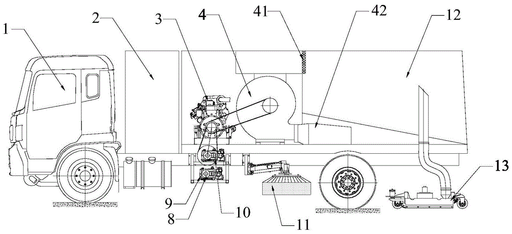
图3是本发明优选实施例的深度清洁作业车的主视结构示意图。FIG. 3 is a schematic front view of the structure of a deep cleaning work vehicle according to a preferred embodiment of the present invention.
图4是本发明优选实施例的深度清洁作业车的俯视结构示意图。FIG. 4 is a schematic top view of the structure of a deep cleaning work vehicle according to a preferred embodiment of the present invention.
图5是本发明优选实施例的深度清洁作业车进行深度清洁作业时的示意图。FIG. 5 is a schematic diagram of the deep cleaning operation vehicle according to the preferred embodiment of the present invention when the deep cleaning operation is performed.
图6是本发明优选实施例的深度清洁作业车进行普通清洁作业时的示意图。FIG. 6 is a schematic diagram of the deep cleaning vehicle according to the preferred embodiment of the present invention when performing ordinary cleaning operations.
图7是图3中的吸嘴组件的主视结构示意图。FIG. 7 is a schematic front view of the structure of the suction nozzle assembly in FIG. 3 .
图8是图3中的吸嘴组件的俯视结构示意图。FIG. 8 is a schematic top view of the structure of the suction nozzle assembly in FIG. 3 .
图9是本发明优选实施例的吸嘴组件中的旋转接头、马达、张紧装置安装在吸嘴体上的俯视结构示意图。FIG. 9 is a schematic top view of the structure of the suction nozzle assembly in which the rotary joint, the motor and the tensioning device are installed on the suction nozzle body according to the preferred embodiment of the present invention.
图10是本发明另一实施例的深度清洁作业车的控制方法的流程示意图。10 is a schematic flowchart of a control method for a deep cleaning work vehicle according to another embodiment of the present invention.
附图标记说明Description of reference numerals
1、底盘;2、清水箱;3、副发动机;4、风机;41、滤网;42、消声器;5、变速箱;6、取力器;7、变量柱塞泵;8、柱塞马达;9、第一高压水泵;10、第二高压水泵;11、扫盘组件;12、垃圾箱;13、吸嘴组件;14、水路控制阀块;15、单向阀;131、前挡板;132、侧喷杆;133、旋转座;134、喷杆气缸;135、旋转喷杆;136、马达;137、张紧装置;138、旋转接头;139、吸嘴口;140、喷嘴;141、后密封板;142、前密封板;143、长喷杆;145、吸嘴体;146、翻转气缸;147、吸嘴轮;148、吸嘴轮安装座。1. Chassis; 2. Clean water tank; 3. Auxiliary engine; 4. Fan; 41. Filter screen; 42. Muffler; 5. Gearbox; 6. Power take-off; 7. Variable displacement piston pump; 8. Piston motor ;9, the first high pressure water pump; 10, the second high pressure water pump; 11, the sweeping plate assembly; 12, the garbage can; 13, the suction nozzle assembly; 14, the water control valve block; 15, the one-way valve; 131, the front baffle ; 132, side spray rod; 133, rotary seat; 134, spray rod cylinder; 135, rotating spray rod; 136, motor; 137, tensioning device; 138, rotary joint; 139, suction nozzle; 140, nozzle; 141 , rear sealing plate; 142, front sealing plate; 143, long spray rod; 145, nozzle body; 146, turning cylinder; 147, nozzle wheel; 148, nozzle wheel mounting seat.
具体实施方式Detailed ways
以下结合附图对本发明的实施例进行详细说明,但是本发明可以由下述所限定和覆盖的多种不同方式实施。The embodiments of the present invention will be described in detail below with reference to the accompanying drawings, but the present invention can be implemented in many different ways as defined and covered below.
如图3至图6所示,本发明的优选实施例提供一种深度清洁作业车,包括底盘1、清水箱2、副发动机3、风机4、变速箱5、取力器6、变量柱塞泵7、柱塞马达8、第一高压水泵9、第二高压水泵10、扫盘组件11、垃圾箱12、吸嘴组件13和水路控制阀块14,所述清水箱2、副发动机3、风机4、变速箱5、第一高压水泵9、第二高压水泵10、扫盘组件11、垃圾箱12、吸嘴组件13和水路控制阀块14均安装在底盘1上,其中,所述吸嘴组件13通过一个提升机构与底盘1连接,通过提升机构可以控制整个吸嘴组件13的上拉和下放。所述取力器6与变速箱5连接,变速箱5与底盘1的发动机连接,所述变量柱塞泵7安装在取力器6上,所述柱塞马达8安装在第一高压水泵9上,所述变量柱塞泵7用于驱动柱塞马达8旋转,从而带动第一高压水泵9旋转输出高压水流,变量柱塞泵7可保证第一高压水泵9转速恒定而不受到底盘1的速度变化影响。所述副发动机3用于带动第二高压水泵10和风机4旋转,具体地,所述副发动机3通过皮带与第二高压水泵10和风机4连接,通过皮带进行传动。所述第二高压水泵10和第一高压水泵9通过管路分别与清水箱2、水路控制阀块14连接,吸嘴组件13包括多个喷水装置,水路控制阀块14通过管路分别与吸嘴组件13的多个喷水装置连接,所述第二高压水泵10和第一高压水泵9旋转后从清水箱2中抽取清水形成高压水流,两路高压水流汇聚后进入水路控制阀块14,由水路控制阀块14控制高压水流的输出,比如控制高压水流同时输出至吸嘴组件13的多个喷水装置,或者控制高压水流输出至吸嘴组件13的一个或两个喷水装置。作为优选的,所述第一高压水泵9和第二高压水泵10的出口端均安装有单向阀15,用于避免两股高压水流合流后对水泵形成反向冲击而损坏水泵。另外,风机4与垃圾箱12连接,垃圾箱12与吸嘴组件13连接,当风机4开始旋转时抽走垃圾箱12和吸嘴组件13内的空气,可在垃圾箱12和吸嘴组件13内产生负压,同时扫盘组件11旋转以将垃圾聚拢至吸嘴组件13的正前方,吸嘴组件13将路面上的垃圾吸拾进垃圾箱12内,垃圾经过垃圾箱12的沉降和过滤处理后留在垃圾箱12内,而较为干净的气流则进入风机4后再由消声器42降噪排出。作为优选的,所述风机4与垃圾箱12连通口处设置有滤网41,用于防止垃圾进入风机4内导致风机4损坏。其中,所述扫盘组件11可以采用水力扫盘和/或扫刷扫盘,当在北方城市使用时,由于北方城市天气较为干燥,扬尘现象严重,可以同时设置水力扫盘和扫刷扫盘,先由水力扫盘进行预湿,再经过扫刷扫盘清扫,可以起到较好的抑尘效果;而当在南方城市使用时,水资源较为丰富,可以采用水力扫盘,可以防止扫刷扫盘带来的二次污染。As shown in FIGS. 3 to 6 , a preferred embodiment of the present invention provides a deep cleaning work vehicle, including a
可以理解,若需对路面进行深度清洁作业时,需要第一高压水泵9、第二高压水泵10和风机4同时进行高功率作业,功率消耗极大。本发明的深度清洁作业车,通过取力器6从底盘1上的变速箱5取力驱动变量柱塞泵7工作,进而驱动第一高压水泵9旋转,有效利用了底盘发动机的资源,而第二高压水泵10和风机4所需功率则由副发动机3承担,从而通过合理分配动力满足了深度清洁功能所需的大功率要求。相比于传统的洗扫车或者道路污染清洁车,前者底盘仅仅用来行走,底盘发动机资源浪费,即使在传统洗扫车上加装副发动机3,副发动机3也无法满足第一高压水泵9、第二高压水泵10和风机4同时工作的大功率需求;而后者则完全由底盘发动机驱动,进行深度清洁作业时,风机4、第一高压水泵9、第二高压水泵10均由液压马达驱动工作,需要在底盘上加装分动箱进行取力来驱动液压马达转动,但是液压传动本身效率低、故障率高,而且需要对车辆的底盘传动结构进行改制,成本昂贵且存在行驶安全风险。It can be understood that, when the road surface needs to be deeply cleaned, the first high-pressure water pump 9, the second high-
具体地,如图7至图9所示,所述吸嘴组件13包括前挡板131、侧喷杆132、旋转座133、喷杆气缸134、旋转喷杆135、马达136、张紧装置137、旋转接头138、吸嘴口139、喷嘴140、后密封板141、前密封板142、长喷杆143、皮带144、吸嘴体145和翻转气缸146,所述吸嘴体145作为吸嘴组件13的结构主体,其固定安装在底盘1上,所述侧喷杆132通过旋转座133固定在吸嘴体145上,所述喷杆气缸134一端与吸嘴体145连接,另一端与侧喷杆132连接,通过喷杆气缸134推动侧喷杆132围绕旋转座133旋转,从而便于调整侧喷杆132的冲洗范围。所述侧喷杆132的数量为两个,分别设置在吸嘴体145的前端两侧,所述长喷杆143设置在吸嘴体145的后端。所述吸嘴体145具有一个内腔,所述吸嘴口139设置在吸嘴体145的上方并与垃圾箱12连通,从而将内腔中的垃圾吸拾进垃圾箱12内。具体地,所述吸嘴口139通过吸管与垃圾箱12连接。所述翻转气缸146一端固定在吸嘴体145上,另一端与前挡板131连接,通过翻转气缸146驱动前挡板131转动,从而可以调整吸嘴体145前端开口大小,例如当需要吸拾大体积的垃圾,如空瓶,可以通过翻转气缸146驱动前挡板131翻转以增大吸嘴体145的前端开口,从而将大体积垃圾吸拾进吸嘴体145内。Specifically, as shown in FIGS. 7 to 9 , the
所述旋转接头138和马达136固定安装在吸嘴体145上,马达136通过皮带与其相邻的两个旋转接头138连接以带动旋转接头138旋转。可以理解,所述旋转接头138的数量为偶数个,具体为2个、4个、6个或者8个。所述旋转接头138上安装有多个旋转喷杆135,多个旋转喷杆135均匀分布,每个旋转喷杆135的末端安装有一个喷嘴140,通过马达136带动旋转喷杆135旋转,所述张紧装置137用于支撑皮带以确保皮带处于张紧状态,从而具有良好的传动效率。所述马达136、张紧装置137、旋转接头138和旋转喷杆135组成了主动旋转型高压射流清洁装置,可以主动旋转式地利用高压水冲洗路面,并且高压水流压力不受行驶速度的影响,确保了深度清洁效果。并且,所述主动旋转型高压射流清洁装置设置在吸嘴口139的前端,经过高压冲洗后产生的垃圾经吸嘴口139吸入垃圾箱12内。作为优选的,所述旋转接头138的数量为4个,一个马达136带动相邻的两个旋转接头138和旋转喷杆135逆时针旋转,另一个马达136带动其相邻的两个旋转接头138和旋转喷杆135顺时针旋转,从而两股冲洗水环在中间位置聚集后汇集到吸嘴口139的前端,由吸嘴口139吸入垃圾箱12内,从而确保污水可以大部分被吸入垃圾箱12内而不会流出吸嘴体145外造成二次污染。可以理解,在本发明的其它实施例中,两个马达136的转动方向也可以相同,即均为逆时针旋转或者顺时针旋转。所述前密封板142和后密封板141配合前挡板131用于将吸嘴体145隔离成一个相对密闭的空间,以提升吸嘴组件13的吸力,具体地,所述前密封板142设置在吸嘴口139和主动旋转型高压射流清洁装置之间,所述后密封板141设置在吸嘴口139和长喷杆143之间,所述前密封板142与地面之间的间隙保持在2.5公分左右,后密封板141与地面之间的间隙保持在1公分左右。可以理解,当在南方城市使用时,扫盘组件11采用水力扫盘,此时可省去侧喷杆132的设置,从而实现高压水流的最优化利用。The rotary joint 138 and the
所述旋转接头138、侧喷杆132和长喷杆143作为吸嘴组件13的喷水装置,其分别通过管路与水路控制阀块14连接,通过水路控制阀块14控制每个水流回路的通断。当需要进行深度清洁作业时,所述水路控制阀块14控制高压水流输出至旋转接头138和侧喷杆132,主动旋转型高压射流清洁装置和侧喷杆132同时工作,其中高压水流经旋转接头138流至每根旋转喷杆135末端的喷嘴140,从而形成多个角度高压冲洗,并且旋转喷杆135在马达136的带动下旋转,从而对路面进行主动旋转式高压冲洗,并且还可以通过调整马达136的转速来控制旋转喷杆135的旋转速度,可以基于车速的改变而改变,例如车速快时控制马达136转速加快,车速慢时控制马达136转速减慢,从而到达最优的经济效益和清洗效果。而当需要进行常规清洁作业时,所述水路控制阀块14控制高压水流输出至侧喷杆132和长喷杆143,结合扫盘组件11清扫,实现常规保洁作业,与传统洗扫车的清洗效果完全一致。另外,当进行常规清洁作业时,还可以控制第一高压水泵9不工作,由第二高压水泵10单独供水,视具体的路面情况来选择是否启用第一高压水泵9。并且通过将侧喷杆132、主动旋转型高压射流清洁装置和长喷杆143集成设置在吸嘴组件13上,不仅实现了集成化设置,有利于实现深度清洁作业车的小型化和轻便化设计,而且便于进行管路布置,节省了安装空间,尤其是在进行深度清洁作业时,侧喷杆132位于主动旋转型高压射流清洁装置的前方,侧喷杆132先对路面进行初步的高压冲洗,然后再由主动旋转型高压射流清洁装置进行多角度旋转时冲洗,两种高压冲洗方式相辅相成,大大提升了深度清洁效果,同时侧喷杆132喷出的水流是散布式的,处于无规则流动状态,清洗后产生的污水很容易扩散到吸嘴体145的工作区域外从而造成二次污染,将侧喷杆132和主动旋转型高压射流清洁装置集成设置在吸嘴体145上且主动旋转型高压射流清洁装置位于侧喷杆132的后端,可以通过主动旋转型高压射流清洁装置喷出的水环对侧喷杆132输出的水流进行引流后,污水汇聚至吸嘴口139处,再从吸嘴口139吸入到垃圾箱12内,减少了扩散的污水量,从而减少了二次污染。另外,可以理解,所述吸嘴口139的数量为多个,可以快速地将路面的污水吸入垃圾箱12内,从而可以提升污水吸拾效率。作为优选的,所述吸嘴口139的数量为四个,在主动旋转型高压射流清洁装置的前方和后方均设置两个吸嘴口139,位于前端的吸嘴口139先将大颗粒、轻飘物、树枝等易于被侧喷杆132冲洗的大件垃圾吸入垃圾箱12内,而路面上粘附的小颗粒污染物则难以被侧喷杆132清除,位于后端的吸嘴口139再将主动旋转型高压射流清洁装置对路面进行高压冲洗后清除产生的小颗粒污染物进行吸拾,确保了良好的深度清洁效果。另外,所述侧喷杆132可以省略,在进行深度清洁作业时仅有主动旋转型高压射流清洁装置进行高压冲洗,而进行普通清洁作业时,则由长喷杆143单独进行冲洗。The rotary joint 138, the
可以理解,作为优选的,所述旋转接头138上安装有三根旋转喷杆135,每根旋转喷杆135上设置有一个喷嘴140。旋转喷杆135的数量多少会同时影响高压水流的覆盖区域和水流冲洗压力,若旋转喷杆135的数量过多,虽然可以确保马达136在低转速情况下也可以覆盖全部清洗区域,但是每个喷嘴140的水流冲洗压力会变得很低,冲洗效果较差,无法满足深度清洁作业要求;而若旋转喷杆135的数量过少,虽然可以确保每个喷嘴140的水流冲洗压力足够大,冲洗效果较好,但是需要提高马达136的转速才能确保覆盖全部区域,增加了能耗。而本发明中优选设置三根旋转喷杆135,既可以确保每个喷嘴140具有足够的水流冲洗压力,又可以使得马达136在较低转速的情况下确保覆盖全部清洗区域。具体地,基于相同的行驶速度和相同的旋转喷杆135数量,当马达136的转速为500r/min时,三个喷嘴140的轨迹没有完全覆盖清洗区域,即相邻的两个喷嘴140的运行轨迹之间存在空白区;当马达136的转速达到700r/min时,三个喷嘴140的轨迹刚好覆盖清洗区域,清洗效果较好,当马达136的转速达到900r/min时,三个喷嘴140的轨迹不仅覆盖了清洗区域而且存在重叠,清洗效果更好,但相应的油耗也较高。因此,可以基于底盘1的不同行驶速度搭配不同的马达136转速,实现车辆行驶速度与旋转喷杆135的旋转速度相匹配,实现最优的清洗效果和最低的作业油耗。It can be understood that, preferably, three rotary spray bars 135 are installed on the rotary joint 138 , and each of the rotary spray bars 135 is provided with a
另外,作为优选的,所述吸嘴组件13还包括吸嘴轮147,所述吸嘴论轮147通过吸嘴轮安装座148固定安装在吸嘴体145上,吸嘴轮147用于稳定支撑整个吸嘴组件13,保证吸嘴体145与地面之间的间隙保持不变,即使遇到路面凹凸不平的区域仍然确保清洗效果的一致性。In addition, preferably, the
可以理解,本发明的吸嘴组件13可以作为单独的产品使用,也可以搭载在深度清洁作业车上使用。It can be understood that the
可以理解,如图10所示,本发明的另一实施例还提供一种深度清洁作业车的控制方法,其采用如上述实施例所述的深度清洁作业车,具体地,所述深度清洁作业车的控制方法包括以下步骤:It can be understood that, as shown in FIG. 10 , another embodiment of the present invention further provides a control method for a deep cleaning operation vehicle, which adopts the deep cleaning operation vehicle described in the above-mentioned embodiment. Specifically, the deep cleaning operation The control method of the vehicle includes the following steps:
步骤S1:基于前方路面的污染程度选择深度清洁作业车的作业模式;Step S1: Select the operation mode of the deep cleaning operation vehicle based on the pollution degree of the road ahead;
步骤S2:当选择深度清洁模式时,控制输出至变量柱塞泵7的电流大小保持恒定,控制水路控制阀块14关闭与长喷杆143连通的管路且打开与侧喷杆132和旋转接头138连通的管路;当选择普通清洁模式时,控制水路控制阀块14打开与侧喷杆132、长喷杆143连通的管路且关闭与旋转接头138连通的管路;Step S2: When the deep cleaning mode is selected, the magnitude of the current output to the variable
步骤S3:当选择深度清洁模式时,控制马达136转动以对路面进行主动旋转式高压冲洗;当选择普通清洁模式时,控制马达136不转动。Step S3: When the deep cleaning mode is selected, the
可以理解,在所述步骤S1中,可以人工目视前方路面的污染程度,当路面污染严重时选择深度清洁模式,确保清洁效果,而当路面污染较轻时则选择普通清洁模式,降低车辆的能耗。另外,还可以基于图像识别技术自动识别前方路面的污染程度,例如可以通过识别前方路面污染区域的面积来判定污染程度等,具体的图像识别技术属于现有技术,故在此不再赘述。另外,作业模式的选择可以通过人为操控驾驶室的按钮或者触控面板来实现,或者基于图像识别技术的结果自动选择作业模式。It can be understood that in the step S1, the degree of pollution of the road ahead can be manually checked, and when the road pollution is serious, the deep cleaning mode is selected to ensure the cleaning effect, and when the road pollution is light, the ordinary cleaning mode is selected to reduce the pollution of the vehicle. energy consumption. In addition, the pollution degree of the road ahead can also be automatically identified based on the image recognition technology, for example, the pollution degree can be determined by identifying the area of the road surface pollution area in front. In addition, the selection of the working mode can be realized by manipulating the buttons or touch panel of the cab, or automatically selecting the working mode based on the results of the image recognition technology.
在所述步骤S2中,当选择深度清洁模式时,车辆控制器会控制输出至变量柱塞泵7的电流大小保持恒定,从而控制柱塞马达8的转速保持恒定,进而控制第一高压水泵9的转速恒定,第一高压水泵9的转速不受车辆行驶速度的影响。作为优选的,控制变量柱塞泵7的电流大小保持为其额定工作电流,从而控制变量柱塞泵7的开度保持最大,柱塞马达8和第一高压水泵9以最高转速工作,从而确保输出的水流压力足够大以获得良好的清洁效果。同时,车辆控制器控制水路控制阀块14关闭与长喷杆143连通的管路且打开与侧喷杆132和旋转接头138连通的管路,此时侧喷杆132和主动旋转型高压射流清洁装置同时工作,进行深度清洁作业。而当选择的是普通清洁模式时,车辆控制器会控制水路控制阀块14打开与侧喷杆132、长喷杆143连通的管路且关闭与旋转接头138连通的管路,此时侧喷杆132和长喷杆143同时工作,进行普通清洁作业,而主动旋转型高压射流清洁装置不工作。另外,当选择普通清洁模式时,车辆控制器还可以控制输出至变量柱塞泵7的电流断开,从而第一高压水泵9不工作,由第二高压水泵10单独供水,从而可以减小车辆的能耗。In the step S2, when the deep cleaning mode is selected, the vehicle controller will control the magnitude of the current output to the variable
在所述步骤S3中,当选择深度清洁模式时,车辆控制器控制马达136转动,主动旋转型高压射流清洁装置对路面进行旋转式高压冲洗,清洁效果更好,并且转速十分稳定,清洁效果保持良好的一致性。而当选择普通清洁作业模式时,高压水流不再输出至主动旋转型高压射流清洁装置,此时车辆控制器控制马达136不转动,降低了车辆的能耗。In the step S3, when the deep cleaning mode is selected, the vehicle controller controls the
作为优选的,所述深度清洁作业车的控制方法还包括以下步骤:Preferably, the control method of the deep cleaning operation vehicle further comprises the following steps:
步骤S4:获取车辆的行驶速度并根据车辆的行驶速度控制马达136的转速。Step S4: Obtain the running speed of the vehicle and control the rotational speed of the
车辆控制器可以获取车辆的当前行驶速度,然后根据车辆的行驶速度选择适配的马达136转速,实现车辆行驶速度与马达136转速的自动匹配,可以取得最优的清洗效果和最低的工作油耗。其中,不同的行驶速度对应的马达136转速已经预先存储在数据库中,只需要获取到车辆的行驶速度后,车辆控制器即可从数据库中自动获取适配的马达136转速。The vehicle controller can obtain the current running speed of the vehicle, and then select the
本发明的深度清洁作业车的控制方法,基于上述深度清洁作业车独特的传动系统和合理的动力分配,即可进行高能耗的深度除污作业,又可以进行低能耗的普通清洁作业,满足不同的工况需求,最大程度提高了车辆的使用效率。并且通过控制马达136的转速与车辆的行驶速度相适配,主动旋转型高压射流清洁装置的转速保持稳定,可以取得最优的清洗效果和最低的工作油耗。The control method of the deep cleaning work vehicle of the present invention, based on the unique transmission system and reasonable power distribution of the deep cleaning work vehicle, can perform deep decontamination operations with high energy consumption and ordinary cleaning operations with low energy consumption, and meet different requirements. meet the requirements of the working conditions, and maximize the efficiency of the use of the vehicle. And by controlling the rotational speed of the
以上所述仅为本发明的优选实施例而已,并不用于限制本发明,对于本领域的技术人员来说,本发明可以有各种更改和变化。凡在本发明的精神和原则之内,所作的任何修改、等同替换、改进等,均应包含在本发明的保护范围之内。The above descriptions are only preferred embodiments of the present invention, and are not intended to limit the present invention. For those skilled in the art, the present invention may have various modifications and changes. Any modification, equivalent replacement, improvement, etc. made within the spirit and principle of the present invention shall be included within the protection scope of the present invention.
Claims (10)
Priority Applications (1)
| Application Number | Priority Date | Filing Date | Title |
|---|---|---|---|
| CN202010617211.5A CN111962444A (en) | 2020-06-30 | 2020-06-30 | A deep cleaning operation vehicle |
Applications Claiming Priority (1)
| Application Number | Priority Date | Filing Date | Title |
|---|---|---|---|
| CN202010617211.5A CN111962444A (en) | 2020-06-30 | 2020-06-30 | A deep cleaning operation vehicle |
Publications (1)
| Publication Number | Publication Date |
|---|---|
| CN111962444A true CN111962444A (en) | 2020-11-20 |
Family
ID=73361117
Family Applications (1)
| Application Number | Title | Priority Date | Filing Date |
|---|---|---|---|
| CN202010617211.5A Pending CN111962444A (en) | 2020-06-30 | 2020-06-30 | A deep cleaning operation vehicle |
Country Status (1)
| Country | Link |
|---|---|
| CN (1) | CN111962444A (en) |
Cited By (3)
| Publication number | Priority date | Publication date | Assignee | Title |
|---|---|---|---|---|
| CN114059488A (en) * | 2021-11-09 | 2022-02-18 | 福建海山机械股份有限公司 | Multifunctional road deep cleaning vehicle |
| CN116856326A (en) * | 2023-07-25 | 2023-10-10 | 中通新能源汽车有限公司 | Pure electric double-motor bridge drives degree of depth cleaning vehicle |
| CN118932910A (en) * | 2024-10-14 | 2024-11-12 | 福建海山机械股份有限公司 | A spray rod control method, cleaning device and electric cleaning vehicle control system |
Citations (7)
| Publication number | Priority date | Publication date | Assignee | Title |
|---|---|---|---|---|
| US20070045445A1 (en) * | 2005-08-26 | 2007-03-01 | Joseph Hackel | Multi-component fluid spraying system |
| CN106638424A (en) * | 2017-02-24 | 2017-05-10 | 福建海山机械股份有限公司 | High-pressure jet cleaning device and road pollution removing vehicle |
| CN107964904A (en) * | 2017-11-08 | 2018-04-27 | 中原特种车辆有限公司 | A kind of LNG sweepers and its wash and sweep operational method |
| CN109518639A (en) * | 2018-12-24 | 2019-03-26 | 烟台杰瑞石油装备技术有限公司 | A kind of high-pressure injection clearing apparatus |
| CN109797692A (en) * | 2019-01-14 | 2019-05-24 | 烟台海德专用汽车有限公司 | A kind of Split rotary bath suction unit |
| CN209975448U (en) * | 2019-04-01 | 2020-01-21 | 中国重汽集团湖北华威专用汽车有限公司 | Novel double dynamical multi-functional washing and sweeping vehicle |
| CN111287132A (en) * | 2020-04-17 | 2020-06-16 | 上海亮土智能科技有限公司 | Linkage type high-pressure cleaning and pumping device |
-
2020
- 2020-06-30 CN CN202010617211.5A patent/CN111962444A/en active Pending
Patent Citations (7)
| Publication number | Priority date | Publication date | Assignee | Title |
|---|---|---|---|---|
| US20070045445A1 (en) * | 2005-08-26 | 2007-03-01 | Joseph Hackel | Multi-component fluid spraying system |
| CN106638424A (en) * | 2017-02-24 | 2017-05-10 | 福建海山机械股份有限公司 | High-pressure jet cleaning device and road pollution removing vehicle |
| CN107964904A (en) * | 2017-11-08 | 2018-04-27 | 中原特种车辆有限公司 | A kind of LNG sweepers and its wash and sweep operational method |
| CN109518639A (en) * | 2018-12-24 | 2019-03-26 | 烟台杰瑞石油装备技术有限公司 | A kind of high-pressure injection clearing apparatus |
| CN109797692A (en) * | 2019-01-14 | 2019-05-24 | 烟台海德专用汽车有限公司 | A kind of Split rotary bath suction unit |
| CN209975448U (en) * | 2019-04-01 | 2020-01-21 | 中国重汽集团湖北华威专用汽车有限公司 | Novel double dynamical multi-functional washing and sweeping vehicle |
| CN111287132A (en) * | 2020-04-17 | 2020-06-16 | 上海亮土智能科技有限公司 | Linkage type high-pressure cleaning and pumping device |
Cited By (3)
| Publication number | Priority date | Publication date | Assignee | Title |
|---|---|---|---|---|
| CN114059488A (en) * | 2021-11-09 | 2022-02-18 | 福建海山机械股份有限公司 | Multifunctional road deep cleaning vehicle |
| CN116856326A (en) * | 2023-07-25 | 2023-10-10 | 中通新能源汽车有限公司 | Pure electric double-motor bridge drives degree of depth cleaning vehicle |
| CN118932910A (en) * | 2024-10-14 | 2024-11-12 | 福建海山机械股份有限公司 | A spray rod control method, cleaning device and electric cleaning vehicle control system |
Similar Documents
| Publication | Publication Date | Title |
|---|---|---|
| CN111962446A (en) | Deep cleaning operation vehicle and control method thereof | |
| CN111962445A (en) | A suction nozzle assembly and a deep cleaning work vehicle using the same | |
| CN202064313U (en) | Multifunctional environment-friendly energy-saving all-weather road surface motor sweeper | |
| CN201165647Y (en) | Multifunctional cleaning road sweeper | |
| KR100959401B1 (en) | Vacuum cleaning vehicle having highpressure sprinkler for removing road pollutions | |
| CN110714431A (en) | Efficient blowing and sucking type sweeping machine and operation method thereof | |
| CN108221793A (en) | Electric sweeper truck clearing apparatus and electric sweeper truck | |
| KR100704375B1 (en) | Road cleaning vehicles | |
| CN206467616U (en) | A kind of cleaning suitable for porous pavement is cared the car | |
| JP5636125B1 (en) | Road cleaning work vehicle | |
| KR100688257B1 (en) | Road vacuum cleaner with dual high pressure water sprayer | |
| CN106638417B (en) | A kind of cleaning suitable for porous pavement cares the car, method and application | |
| CN109797692A (en) | A kind of Split rotary bath suction unit | |
| CN220847323U (en) | Roller type dust fall and dust suppression cleaning structure applied to road construction sweeper | |
| CN214530416U (en) | Washing and sweeping system of washing and sweeping vehicle and washing and sweeping vehicle | |
| CN110565567A (en) | Sweeping vehicle with sidewalk fallen leaf collecting and dirt absorbing functions | |
| KR200414481Y1 (en) | Road cleaning vehicles | |
| CN211815905U (en) | Multifunctional road pollution removing vehicle | |
| CN209836894U (en) | Multifunctional sweeping vehicle | |
| CN200940260Y (en) | Vehicle for cleaning curb and curb stone of urban road | |
| CN212714752U (en) | A high and low pressure water separation system for a sweeper | |
| CN114411606A (en) | Cleaning mechanism and road sweeper | |
| CN106759031B (en) | A road cleaning method and road cleaning vehicle | |
| CN110541379A (en) | Motor sweeper with purging function | |
| CN218880693U (en) | Inhale groove unit and clean groove of inhaling |
Legal Events
| Date | Code | Title | Description |
|---|---|---|---|
| PB01 | Publication | ||
| PB01 | Publication | ||
| SE01 | Entry into force of request for substantive examination | ||
| SE01 | Entry into force of request for substantive examination | ||
| CB02 | Change of applicant information | ||
| CB02 | Change of applicant information |
Country or region after: China Address after: 410221 Hunan Province Changsha City Gaoxin Development Zone Linyu Road 288.NO Applicant after: Changsha Yingfeng Environmental Industry Co.,Ltd. Address before: 410003 Hunan Province, Changsha City, Gaoxin Development Zone, Linyu Road 288 Applicant before: ZOOMLION ENVIRONMENTAL INDUSTRY Co.,Ltd. Country or region before: China |