CN111908759A - Plate-and-frame filter press for sludge dewatering - Google Patents
Plate-and-frame filter press for sludge dewatering Download PDFInfo
- Publication number
- CN111908759A CN111908759A CN202010683302.9A CN202010683302A CN111908759A CN 111908759 A CN111908759 A CN 111908759A CN 202010683302 A CN202010683302 A CN 202010683302A CN 111908759 A CN111908759 A CN 111908759A
- Authority
- CN
- China
- Prior art keywords
- plate
- sludge
- filter press
- crushing
- welded
- Prior art date
- Legal status (The legal status is an assumption and is not a legal conclusion. Google has not performed a legal analysis and makes no representation as to the accuracy of the status listed.)
- Pending
Links
- 239000010802 sludge Substances 0.000 title claims abstract description 68
- 238000003825 pressing Methods 0.000 claims abstract description 36
- 230000000149 penetrating effect Effects 0.000 claims abstract description 16
- 239000000706 filtrate Substances 0.000 claims abstract description 12
- 239000000463 material Substances 0.000 claims description 24
- 239000007788 liquid Substances 0.000 claims description 13
- 238000003466 welding Methods 0.000 claims description 10
- 238000007599 discharging Methods 0.000 claims description 6
- 238000005096 rolling process Methods 0.000 claims description 3
- XLYOFNOQVPJJNP-UHFFFAOYSA-N water Substances O XLYOFNOQVPJJNP-UHFFFAOYSA-N 0.000 description 8
- 238000006297 dehydration reaction Methods 0.000 description 7
- 230000018044 dehydration Effects 0.000 description 6
- 238000000034 method Methods 0.000 description 6
- 239000010865 sewage Substances 0.000 description 5
- 230000009286 beneficial effect Effects 0.000 description 4
- 239000007787 solid Substances 0.000 description 4
- 238000001035 drying Methods 0.000 description 3
- 238000001125 extrusion Methods 0.000 description 3
- 238000001914 filtration Methods 0.000 description 3
- 238000004140 cleaning Methods 0.000 description 2
- 238000005469 granulation Methods 0.000 description 2
- 230000003179 granulation Effects 0.000 description 2
- 238000000227 grinding Methods 0.000 description 2
- 239000010813 municipal solid waste Substances 0.000 description 2
- 238000000926 separation method Methods 0.000 description 2
- 230000001112 coagulating effect Effects 0.000 description 1
- 230000003750 conditioning effect Effects 0.000 description 1
- 238000010586 diagram Methods 0.000 description 1
- 239000003814 drug Substances 0.000 description 1
- 229940079593 drug Drugs 0.000 description 1
- 239000012065 filter cake Substances 0.000 description 1
- 239000012530 fluid Substances 0.000 description 1
- 238000011084 recovery Methods 0.000 description 1
- 239000013049 sediment Substances 0.000 description 1
- 238000004062 sedimentation Methods 0.000 description 1
- 239000010801 sewage sludge Substances 0.000 description 1
Images


Classifications
-
- C—CHEMISTRY; METALLURGY
- C02—TREATMENT OF WATER, WASTE WATER, SEWAGE, OR SLUDGE
- C02F—TREATMENT OF WATER, WASTE WATER, SEWAGE, OR SLUDGE
- C02F11/00—Treatment of sludge; Devices therefor
- C02F11/12—Treatment of sludge; Devices therefor by de-watering, drying or thickening
- C02F11/121—Treatment of sludge; Devices therefor by de-watering, drying or thickening by mechanical de-watering
- C02F11/122—Treatment of sludge; Devices therefor by de-watering, drying or thickening by mechanical de-watering using filter presses
-
- B—PERFORMING OPERATIONS; TRANSPORTING
- B01—PHYSICAL OR CHEMICAL PROCESSES OR APPARATUS IN GENERAL
- B01D—SEPARATION
- B01D25/00—Filters formed by clamping together several filtering elements or parts of such elements
- B01D25/12—Filter presses, i.e. of the plate or plate and frame type
- B01D25/21—Plate and frame presses
-
- B—PERFORMING OPERATIONS; TRANSPORTING
- B02—CRUSHING, PULVERISING, OR DISINTEGRATING; PREPARATORY TREATMENT OF GRAIN FOR MILLING
- B02C—CRUSHING, PULVERISING, OR DISINTEGRATING IN GENERAL; MILLING GRAIN
- B02C18/00—Disintegrating by knives or other cutting or tearing members which chop material into fragments
- B02C18/0084—Disintegrating by knives or other cutting or tearing members which chop material into fragments specially adapted for disintegrating garbage, waste or sewage
-
- B—PERFORMING OPERATIONS; TRANSPORTING
- B02—CRUSHING, PULVERISING, OR DISINTEGRATING; PREPARATORY TREATMENT OF GRAIN FOR MILLING
- B02C—CRUSHING, PULVERISING, OR DISINTEGRATING IN GENERAL; MILLING GRAIN
- B02C18/00—Disintegrating by knives or other cutting or tearing members which chop material into fragments
- B02C18/06—Disintegrating by knives or other cutting or tearing members which chop material into fragments with rotating knives
- B02C18/08—Disintegrating by knives or other cutting or tearing members which chop material into fragments with rotating knives within vertical containers
- B02C18/10—Disintegrating by knives or other cutting or tearing members which chop material into fragments with rotating knives within vertical containers with drive arranged above container
-
- B—PERFORMING OPERATIONS; TRANSPORTING
- B02—CRUSHING, PULVERISING, OR DISINTEGRATING; PREPARATORY TREATMENT OF GRAIN FOR MILLING
- B02C—CRUSHING, PULVERISING, OR DISINTEGRATING IN GENERAL; MILLING GRAIN
- B02C2201/00—Codes relating to disintegrating devices adapted for specific materials
- B02C2201/06—Codes relating to disintegrating devices adapted for specific materials for garbage, waste or sewage
Landscapes
- Engineering & Computer Science (AREA)
- Chemical & Material Sciences (AREA)
- Environmental & Geological Engineering (AREA)
- Food Science & Technology (AREA)
- Mechanical Engineering (AREA)
- Chemical Kinetics & Catalysis (AREA)
- Life Sciences & Earth Sciences (AREA)
- Hydrology & Water Resources (AREA)
- Water Supply & Treatment (AREA)
- Organic Chemistry (AREA)
- Treatment Of Sludge (AREA)
Abstract
The invention relates to the technical field of plate-and-frame filter presses, in particular to a plate-and-frame filter press for sludge dewatering, which comprises a frame body, wherein a sludge discharge member is arranged at the lower end in the frame body, a sludge block box is welded at the position, below the sludge discharge member, of one side of the lower end of the frame body, a thrust plate is welded at one side of the upper end of the frame body, a feeding member is arranged on the outer surface of one side of the thrust plate in a penetrating manner, a filter pressing plate is arranged at the other side of the thrust plate, a push plate is arranged on the outer surface of one side of the filter pressing plate, an air cylinder is arranged on the outer surface of one side of the push plate, a filtrate discharge pipe is arranged on the front surface. The plate-and-frame filter press for sludge dewatering is provided with a sludge introducing and crushing member, a filter press plate and a frame body are connected in a sliding mode through rollers, and a sludge block collecting and guiding structure is arranged.
Description
Technical Field
The invention relates to the technical field of plate-and-frame filter presses, in particular to a plate-and-frame filter press for sludge dewatering.
Background
A sludge treatment method is provided for removing water from fluid primary, concentrated or digested sludge and converting the sludge into semi-solid or solid sludge blocks. After dewatering, the water content of the sludge can be reduced to fifty-five percent to eighty percent, depending on the properties of the sludge and the sediments and the efficiency of the dewatering equipment. The further dehydration of the sludge is called sludge drying, and the moisture content of the dried sludge is less than ten percent. The dehydration method mainly comprises a natural drying method, a mechanical dehydration method and a granulation method, wherein the natural drying method and the mechanical dehydration method are suitable for sewage sludge, the granulation method is suitable for coagulating sedimentation sludge, a plate-and-frame filter press is a machine which is firstly applied to chemical dehydration, and although the plate-and-frame filter press is generally operated intermittently, the capital equipment investment is large, and the filtering capacity is low, the plate-and-frame filter press has the advantages of large filtering driving force, high solid content of filter cakes, clear filtrate, high solid recovery rate, low consumption of conditioning drugs and the like, and is still widely applied to some small sewage plants.
Chinese patent discloses a plate and frame filter press, (No. CN210448224U is announced to the grant), but, the plate and frame filter press of sludge dewatering on the existing market, can not carry out the breakage to the great rubbish of volume in the sewage of leading into, be unfavorable for the filter-pressing of device, lead to into water the department and block up, be unfavorable for the smoothness nature of device operation, most filter-pressing boards support through the backup pad at the upper surface of device and place, gliding smoothness nature is relatively poor, be unfavorable for the extrusion dehydration, be unfavorable for the separation of filter plate to take out the clod, clean efficiency is lower, do not have the clod to collect and derive the structure greatly, be unfavorable for the clod fixed point and discharge, lead to the clod to drop inside. Accordingly, one skilled in the art provides a plate and frame filter press for sludge dewatering to solve the problems set forth in the background art described above.
Disclosure of Invention
The invention aims to provide a plate-and-frame filter press for sludge dewatering, which solves the problems in the prior art.
In order to achieve the purpose, the invention provides the following technical scheme: the utility model provides a filter press for sludge dewatering, includes the support body, the inside lower extreme of support body is installed the mud and is derived the component, the lower one end one side of support body is located the below position department welding that the mud derived the component and has the clod case, the upper end one side welding of support body has the thrust plate, one side surface link up of thrust plate installs the feeding component, the filter-pressing board is installed to the opposite side of thrust plate, one side surface mounting of filter-pressing board has the push pedal, one side surface mounting of push pedal has the cylinder, surface mounting has the filtrating discharge pipe before the lower extreme of filter-pressing board, the spout has been seted up to the upper surface of support body, surface mounting has the gyro wheel before the filter-pressing board, the flowing back valve is.
As a further scheme of the invention: the mud is derived the upper end of component and is provided with clod and collects the fill, the lower surface that the clod was collected the fill link up the welding and is passed the material pipe, the inside rotation that passes the material pipe is installed the hob, the one end lower surface that passes the material pipe link up the welding and is had a mud outlet, the surface mounting has the conveying motor on one side of passing the material pipe, the outer surface welding that the clod was collected the fill has the backup pad.
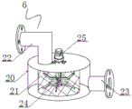
As a still further scheme of the invention: the one end of feeding component is provided with smashes the chamber, the inside welding in crushing chamber has crushing net bucket, the upper surface through welding that smashes net bucket has the feed liquor pipe, the lower extreme one side through welding that smashes the chamber has the biography material pipe, the inside rotation of smashing net bucket is installed and is smashed the sword leaf, the last surface mounting who smashes the chamber has crushing motor.
As a still further scheme of the invention: the output end of the feeding component is in through connection with the input end of the thrust plate, the output end of the thrust plate is in through connection with the input end of the filter pressing plate, and the output end of the filter pressing plate is in through connection with the input end of the filtrate discharge pipe.
As a still further scheme of the invention: the front and rear ends of the upper surface of the frame body are provided with chutes, the front and rear outer surfaces of the press filter plate are provided with rollers, and the rollers are arranged at the inner positions of the chutes in a rolling manner.
As a still further scheme of the invention: the one end of the interior pole of cylinder welds in the surface one side position department of push pedal, the one end of the outer pole of cylinder welds in the surface of support body and the one side position department that the push pedal corresponds.
As a still further scheme of the invention: the utility model discloses a mud piece collecting hopper, including support body, hob, conveying motor, mud piece collecting hopper, support plate, screw rod, conveying pipe, supporting plate, bracket, screw rod, conveying pipe, support plate, screw rod, conveying motor, support plate, bracket.
As a still further scheme of the invention: the mud block collecting hopper is corresponding to the lower part of the filter pressing plate, the length of the mud block collecting hopper is 1.5 times of the stacking length of the filter pressing plate, and the mud outlet is positioned above the mud block box.
As a still further scheme of the invention: the feeding component is connected with the input end of the thrust plate in a penetrating way through the material conveying pipe, the crushing blade is rotatably installed at the inner position of the crushing net barrel through the crushing motor, and the output end of the liquid inlet pipe penetrates through the crushing cavity and is connected with the upper surface of the crushing net barrel in a penetrating way.
Compared with the prior art, the invention has the beneficial effects that: the plate-and-frame filter press for sludge dewatering is provided with the introduced sludge crushing member, can crush garbage with larger volume in introduced sewage, is beneficial to filter pressing of a device, avoids blockage at a water inlet and is beneficial to smoothness of operation of the device, the filter pressing plate is in sliding connection with the frame body through the roller, the sliding smoothness of the filter pressing plate is beneficial to extrusion dewatering, separation of the filter plates is facilitated, mud blocks are convenient to take out, cleaning efficiency is improved, a mud block collecting and guiding structure is arranged, the mud blocks are discharged at fixed points, the mud blocks are prevented from falling into filtrate, and convenience in cleaning of the mud blocks is improved.
Drawings
FIG. 1 is a schematic diagram of a plate and frame filter press for sludge dewatering;
FIG. 2 is a schematic view of a partial structure in a plate and frame filter press for sludge dewatering;
FIG. 3 is a schematic view of a partial structure in a plate and frame filter press for sludge dewatering;
FIG. 4 is a perspective view of a sludge discharge member in a plate-and-frame filter press for sludge dewatering;
figure 5 is a perspective view of a feed member in a plate and frame filter press for sludge dewatering.
In the figure: 1. a frame body; 2. a thrust plate; 3. pressing the filter plate; 4. pushing the plate; 5. a cylinder; 6. a feed member; 7. a filtrate discharge pipe; 8. a sludge discharge member; 9. a mud cake box; 11. a chute; 12. a roller; 13. a drain valve; 14. a mud cake collecting hopper; 15. a material conveying pipe; 16. a support plate; 17. a screw rod; 18. a sludge outlet; 19. a transfer motor; 20. a grinding chamber; 21. a crushing mesh barrel; 22. a liquid inlet pipe; 23. a material conveying pipe; 24. crushing the cutter blades; 25. a grinding motor.
Detailed Description
The technical solutions in the embodiments of the present invention will be clearly and completely described below with reference to the drawings in the embodiments of the present invention, and it is obvious that the described embodiments are only a part of the embodiments of the present invention, and not all of the embodiments. All other embodiments, which can be derived by a person skilled in the art from the embodiments given herein without making any creative effort, shall fall within the protection scope of the present invention.
Referring to fig. 1 to 5, in the embodiment of the present invention, a plate-and-frame filter press for sludge dewatering includes a frame body 1, a sludge discharging member 8 is installed at a lower end of an inside of the frame body 1, a sludge block box 9 is welded at a position below the sludge discharging member 8 at one side of a lower end of the frame body 1, a thrust plate 2 is welded at one side of an upper end of the frame body 1, a feeding member 6 is installed on an outer surface of one side of the thrust plate 2 in a penetrating manner, a filter pressing plate 3 is installed at the other side of the thrust plate 2, a pushing plate 4 is installed on an outer surface of one side of the filter pressing plate 3, an air cylinder 5 is installed on an outer surface of one side of the pushing plate 4, a filtrate discharging pipe 7 is installed on a front surface of a lower end of the filter pressing plate 3, a chute 11 is opened on an upper surface of the frame body 1, the output end of the thrust plate 2 is connected with the input end of the filter pressing plate 3 in a penetrating way, the output end of the filter pressing plate 3 is connected with the input end of the filtrate discharge pipe 7 in a penetrating way, the front and rear positions of the upper surface of the frame body 1 are all provided with chutes 11, the front and rear outer surfaces of the filter pressing plate 3 are all provided with rollers 12, the rollers 12 are arranged at the inner positions of the chutes 11 in a rolling way, one end of the inner rod of the cylinder 5 is welded at one side position of the outer surface of the push plate 4, one end of the outer rod of the cylinder 5 is welded at one side position of the outer surface of the frame body 1 corresponding to the push plate 4, firstly, the device is taken out and placed at the using position, the external sewage end is connected with the device through the liquid inlet pipe 22, then, the device is opened, the external high-pressure sludge pump runs, sludge is introduced into the interior of the filter pressing plate 3 after being crushed, cylinder 5 moves, through push pedal 4 extrusion filter-pressing board 3, to the mud dehydration, the water liquid of deviating from is discharged through filtrating discharge pipe 7, and finally, cylinder 5 drives push pedal 4 shrink, slides through gyro wheel 12 in the inside of spout 11 and removes filter-pressing board 3, and the inside clod of clean filter-pressing board 3 is derived the component 8 through the mud and is connect and get the inside of smashing the clod and deriving mud piece case 9, and after the inside clod of clod case 9 was collected and is full, the inside clod of clearance clod case 9.
In fig. 4: a mud block collecting hopper 14 is arranged at the upper end of the mud pollution guiding-out component 8, a material conveying pipe 15 is welded on the lower surface of the mud block collecting hopper 14 in a penetrating way, a screw rod 17 is rotatably arranged in the material conveying pipe 15, a mud outlet 18 is welded on the lower surface of one end of the material conveying pipe 15 in a penetrating way, a conveying motor 19 is arranged on the outer surface of one side of the material conveying pipe 15, a supporting plate 16 is welded on one side of the outer surface of the mud block collecting hopper 14, the screw rod 17 is rotatably arranged at the inner position of the material conveying pipe 15 through the conveying motor 19, the mud block collecting hopper 14 is welded at the lower end position of the inner side of the frame body 1 through the supporting plate 16, the mud block collecting hopper 14 corresponds to the lower part of the filter pressing plate 3, the length of the mud block collecting hopper 14 is 1.5 times of the superposed length of the filter pressing plate 3, the mud outlet 18 is arranged at the upper position of the mud, the inside clod of clean filter-pressing board 3, the clod drops the inside of clod collection fill 14, and the operation of conveying motor 19 drives the hob 17 and rotates in the inside of passing the material pipe 15, smashes the inside clod of clod collection fill 14, leads out the inside of clod case 9 through mud outlet 18.
In fig. 5: a crushing cavity 20 is arranged at one end of the feeding component 6, a crushing mesh barrel 21 is welded inside the crushing cavity 20, a liquid inlet pipe 22 is welded on the upper surface of the crushing mesh barrel 21 in a penetrating way, a material conveying pipe 23 is welded on one side of the lower end of the crushing cavity 20 in a penetrating way, a crushing blade 24 is rotatably installed inside the crushing mesh barrel 21, a crushing motor 25 is installed on the upper surface of the crushing cavity 20, the feeding component 6 is in a penetrating way with the input end of the thrust plate 2 through the material conveying pipe 23, the crushing blade 24 is rotatably installed at the inner position of the crushing mesh barrel 21 through the crushing motor 25, the output end of the liquid inlet pipe 22 penetrates through the crushing cavity 20 and is in a penetrating way with the upper surface of the crushing mesh barrel 21, an external high-pressure sludge pump operates to convey sludge to the inside of the crushing mesh barrel 21 through the liquid inlet pipe 22, fine sludge enters the inside of the crushing cavity 20 after being filtered by the crushing mesh, sludge having a large volume inside the crushing screen drum 21 is crushed and then introduced into the inside of the filter press plate 3 through the material transfer pipe 23.
It should be noted that: the cylinder 5 (model cdj2b16-15+2-xc11), the conveying motor 19 and the crushing motor 25 are both (model C6BLD 400).
The working principle of the invention is as follows: firstly, taking out the device, placing the device at a use position, connecting an external sewage end with the device through a liquid inlet pipe 22, then, opening the device, operating an external high-pressure sludge pump, conveying sludge to the inside of a crushing mesh barrel 21 through the liquid inlet pipe 22, filtering fine sludge through the crushing mesh barrel 21, then entering the inside of a crushing cavity 20, operating a crushing motor 25, driving crushing blades 24 to rotate, crushing sludge with larger volume in the crushing mesh barrel 21, guiding the crushed sludge into the inside of a filter pressing plate 3 through a conveying pipe 23, opening a liquid discharge valve 13, discharging filtrate through a filtrate discharge pipe 7, when the water pressure at the water inlet reaches a rated value, operating an air cylinder 5, extruding the filter pressing plate 3 through a push plate 4, dehydrating the sludge, discharging the separated water through the filtrate discharge pipe 7, finally, driving the push plate 4 to shrink by the air cylinder 5, sliding and moving the filter pressing plate 3 in a sliding groove 11 through a roller 12, the inside clod of clean filter-pressing board 3, the clod drops the inside that the clod collected fill 14, and the operation of conveying motor 19 drives the hob 17 and rotates in the inside of biography charging tube 15, collects the clod of fighting 14 inside and smashes the clod, leads out the inside of clod case 9 through mud outlet 18, collects the back when the inside clod of clod case 9, clears up the inside clod of clod case 9.
It will be evident to those skilled in the art that the invention is not limited to the details of the foregoing illustrative embodiments, and that the present invention may be embodied in other specific forms without departing from the spirit or essential attributes thereof. The present embodiments are therefore to be considered in all respects as illustrative and not restrictive, the scope of the invention being indicated by the appended claims rather than by the foregoing description, and all changes which come within the meaning and range of equivalency of the claims are therefore intended to be embraced therein. Any reference sign in a claim should not be construed as limiting the claim concerned.
Furthermore, it should be understood that although the present description refers to embodiments, not every embodiment may contain only a single embodiment, and such description is for clarity only, and those skilled in the art should integrate the description, and the embodiments may be combined as appropriate to form other embodiments understood by those skilled in the art.
Claims (9)
1. The utility model provides a plate and frame filter press for sludge dewatering, includes support body (1), its characterized in that, the inside lower extreme of support body (1) is installed the mud and is derived component (8), the welding of the below position department that lower one end one side of support body (1) is located mud and derives component (8) has clod case (9), the welding of upper end one side of support body (1) has thrust plate (2), feeding component (6) are installed to one side surface link up of thrust plate (2), filter plate (3) are installed to the opposite side of thrust plate (2), one side surface mounting of filter plate (3) has push pedal (4), one side surface mounting of push pedal (4) has cylinder (5), surface mounting has filtrating discharge pipe (7) before the lower extreme of filter plate (3), spout (11) have been seted up to the upper surface of support body (1), the front surface of the filter pressing plate (3) is provided with a roller (12), and one end of the filtrate discharge pipe (7) is provided with a liquid discharge valve (13).
2. The plate-and-frame filter press for sludge dewatering according to claim 1, wherein a sludge block collecting hopper (14) is arranged at the upper end of the sludge discharging member (8), a material conveying pipe (15) is welded on the lower surface of the sludge block collecting hopper (14) in a penetrating manner, a screw rod (17) is rotatably arranged inside the material conveying pipe (15), a sludge outlet (18) is welded on the lower surface of one end of the material conveying pipe (15) in a penetrating manner, a conveying motor (19) is arranged on the outer surface of one side of the material conveying pipe (15), and a supporting plate (16) is welded on one side of the outer surface of the sludge block collecting hopper (14).
3. The plate-and-frame filter press for sludge dewatering according to claim 1, wherein a crushing cavity (20) is arranged at one end of the feeding member (6), a crushing mesh barrel (21) is welded inside the crushing cavity (20), a liquid inlet pipe (22) is welded on the upper surface of the crushing mesh barrel (21) in a penetrating manner, a material conveying pipe (23) is welded on one side of the lower end of the crushing cavity (20) in a penetrating manner, a crushing blade (24) is rotatably installed inside the crushing mesh barrel (21), and a crushing motor (25) is installed on the upper surface of the crushing cavity (20).
4. The plate-and-frame filter press for sludge dewatering according to claim 1, wherein the output end of the feeding member (6) is connected through with the input end of the thrust plate (2), the output end of the thrust plate (2) is connected through with the input end of the filter press plate (3), and the output end of the filter press plate (3) is connected through with the input end of the filtrate discharge pipe (7).
5. The plate-and-frame filter press for sludge dewatering according to claim 1, wherein the frame body (1) is provided with sliding chutes (11) at the front and rear positions of the upper surface, the filter press plates (3) are provided with rollers (12) at the front and rear outer surfaces thereof, and the rollers (12) are arranged in the sliding chutes (11) in a rolling manner.
6. The plate-and-frame filter press for sludge dewatering according to claim 1, wherein one end of the inner rod of the air cylinder (5) is welded at one side position of the outer surface of the push plate (4), and one end of the outer rod of the air cylinder (5) is welded at one side position of the outer surface of the frame body (1) corresponding to the push plate (4).
7. The plate-and-frame filter press for sludge dewatering according to claim 2, wherein the screw rod (17) is rotatably mounted at an inner position of the material conveying pipe (15) by a conveying motor (19), and the clod collecting hopper (14) is welded at an inner lower end position of the frame body (1) by a supporting plate (16).
8. The plate-and-frame filter press for sludge dewatering according to claim 2, wherein the sludge block collecting hopper (14) corresponds to the lower part of the filter-pressing plate (3), the length of the sludge block collecting hopper (14) is 1.5 times the overlapping length of the filter-pressing plate (3), and the sludge outlet (18) is located at the upper position of the sludge block tank (9).
9. The plate-and-frame filter press for sludge dewatering according to claim 3, wherein the feeding member (6) is connected with the input end of the thrust plate (2) through a material conveying pipe (23), the crushing blade (24) is rotatably mounted at the inner position of the crushing mesh barrel (21) through a crushing motor (25), and the output end of the liquid inlet pipe (22) penetrates through the crushing cavity (20) and is connected with the upper surface of the crushing mesh barrel (21).
Priority Applications (1)
| Application Number | Priority Date | Filing Date | Title |
|---|---|---|---|
| CN202010683302.9A CN111908759A (en) | 2020-07-16 | 2020-07-16 | Plate-and-frame filter press for sludge dewatering |
Applications Claiming Priority (1)
| Application Number | Priority Date | Filing Date | Title |
|---|---|---|---|
| CN202010683302.9A CN111908759A (en) | 2020-07-16 | 2020-07-16 | Plate-and-frame filter press for sludge dewatering |
Publications (1)
| Publication Number | Publication Date |
|---|---|
| CN111908759A true CN111908759A (en) | 2020-11-10 |
Family
ID=73280162
Family Applications (1)
| Application Number | Title | Priority Date | Filing Date |
|---|---|---|---|
| CN202010683302.9A Pending CN111908759A (en) | 2020-07-16 | 2020-07-16 | Plate-and-frame filter press for sludge dewatering |
Country Status (1)
| Country | Link |
|---|---|
| CN (1) | CN111908759A (en) |
Cited By (3)
| Publication number | Priority date | Publication date | Assignee | Title |
|---|---|---|---|---|
| CN112370832A (en) * | 2020-12-03 | 2021-02-19 | 苏诗涵 | Top plate pressing device convenient to operate and used for filter press and using method of top plate pressing device |
| CN113880303A (en) * | 2021-10-27 | 2022-01-04 | 无锡爱博金属制品有限公司 | Electrophoresis waste liquid purifier |
| CN117065633A (en) * | 2023-08-03 | 2023-11-17 | 绍兴泰谱环保科技有限公司 | A rapid filtration and dewatering device for air flotation sludge |
Citations (4)
| Publication number | Priority date | Publication date | Assignee | Title |
|---|---|---|---|---|
| CN208852483U (en) * | 2018-08-01 | 2019-05-14 | 天津渤化环境修复股份有限公司 | A kind of plate and frame filter press |
| CN209221586U (en) * | 2018-11-08 | 2019-08-09 | 湖北江宸新能源科技有限公司 | A kind of efficient receiving hopper of plate and frame filter press |
| CN210331795U (en) * | 2019-07-08 | 2020-04-17 | 长春天新合成材料有限公司 | Plate-and-frame filter press for preparing lubricating grease |
| CN210698966U (en) * | 2019-09-27 | 2020-06-09 | 惠州市精田机械制造有限公司 | Automatic feeding device of filter press |
-
2020
- 2020-07-16 CN CN202010683302.9A patent/CN111908759A/en active Pending
Patent Citations (4)
| Publication number | Priority date | Publication date | Assignee | Title |
|---|---|---|---|---|
| CN208852483U (en) * | 2018-08-01 | 2019-05-14 | 天津渤化环境修复股份有限公司 | A kind of plate and frame filter press |
| CN209221586U (en) * | 2018-11-08 | 2019-08-09 | 湖北江宸新能源科技有限公司 | A kind of efficient receiving hopper of plate and frame filter press |
| CN210331795U (en) * | 2019-07-08 | 2020-04-17 | 长春天新合成材料有限公司 | Plate-and-frame filter press for preparing lubricating grease |
| CN210698966U (en) * | 2019-09-27 | 2020-06-09 | 惠州市精田机械制造有限公司 | Automatic feeding device of filter press |
Cited By (3)
| Publication number | Priority date | Publication date | Assignee | Title |
|---|---|---|---|---|
| CN112370832A (en) * | 2020-12-03 | 2021-02-19 | 苏诗涵 | Top plate pressing device convenient to operate and used for filter press and using method of top plate pressing device |
| CN113880303A (en) * | 2021-10-27 | 2022-01-04 | 无锡爱博金属制品有限公司 | Electrophoresis waste liquid purifier |
| CN117065633A (en) * | 2023-08-03 | 2023-11-17 | 绍兴泰谱环保科技有限公司 | A rapid filtration and dewatering device for air flotation sludge |
Similar Documents
| Publication | Publication Date | Title |
|---|---|---|
| CN107012706B (en) | A kind of paper mill pulping device | |
| CN211158764U (en) | Pectin squeezes and filters recovery unit | |
| CN214050607U (en) | A filter pressing device for municipal solid waste | |
| CN119869008B (en) | Multistage extraction equipment and process for plant extraction | |
| CN216095520U (en) | Kitchen waste treatment equipment | |
| CN212246935U (en) | Camellia seed squeezing device convenient for solid-liquid separation | |
| CN221620326U (en) | Kitchen waste recycling device | |
| CN210560028U (en) | Adsorption type sludge dewatering equipment | |
| CN112044931A (en) | Recovery plant for crushing and compressing urban living dry garbage | |
| CN217857954U (en) | Garbage extrusion device for garbage transfer station | |
| CN217031955U (en) | Extrusion dehydrator for kitchen waste treatment | |
| CN216472793U (en) | Efficient anti-blocking sludge dewatering device | |
| CN2392592Y (en) | Filtering, lifting and dewatering three-in-one solid-liquid separator | |
| CN213675610U (en) | Natural plant extraction and purification device | |
| CN209317172U (en) | A kind of continous way separating dry space from moist space device | |
| CN209336142U (en) | A kind of dry-wet filter | |
| CN220008931U (en) | A new type of oil and water dry and wet separator for intelligent kitchen recycling | |
| CN216320278U (en) | Waste treatment device for chemical industry | |
| CN113476913A (en) | Efficient treatment method and treatment equipment for river sewage | |
| CN223324591U (en) | Waste collection device | |
| CN219517980U (en) | Plant extract separation and purification device | |
| CN223175984U (en) | An environmentally friendly mud-water separation equipment for sludge treatment | |
| CN215963766U (en) | High-efficient collection device of solid useless filtration liquid | |
| CN111905420A (en) | Domestic sewage treatment equipment | |
| CN216063469U (en) | Wet garbage reduction equipment |
Legal Events
| Date | Code | Title | Description |
|---|---|---|---|
| PB01 | Publication | ||
| PB01 | Publication | ||
| SE01 | Entry into force of request for substantive examination | ||
| SE01 | Entry into force of request for substantive examination | ||
| RJ01 | Rejection of invention patent application after publication | ||
| RJ01 | Rejection of invention patent application after publication |
Application publication date: 20201110 |