CN111908231A - Novel tension control method for high-speed intermittent traction - Google Patents
Novel tension control method for high-speed intermittent traction Download PDFInfo
- Publication number
- CN111908231A CN111908231A CN202010310288.8A CN202010310288A CN111908231A CN 111908231 A CN111908231 A CN 111908231A CN 202010310288 A CN202010310288 A CN 202010310288A CN 111908231 A CN111908231 A CN 111908231A
- Authority
- CN
- China
- Prior art keywords
- tension
- speed
- unwinding
- traction
- roller
- Prior art date
- Legal status (The legal status is an assumption and is not a legal conclusion. Google has not performed a legal analysis and makes no representation as to the accuracy of the status listed.)
- Withdrawn
Links
Images
Classifications
-
- B—PERFORMING OPERATIONS; TRANSPORTING
- B65—CONVEYING; PACKING; STORING; HANDLING THIN OR FILAMENTARY MATERIAL
- B65H—HANDLING THIN OR FILAMENTARY MATERIAL, e.g. SHEETS, WEBS, CABLES
- B65H23/00—Registering, tensioning, smoothing or guiding webs
- B65H23/04—Registering, tensioning, smoothing or guiding webs longitudinally
- B65H23/26—Registering, tensioning, smoothing or guiding webs longitudinally by transverse stationary or adjustable bars or rollers
-
- B—PERFORMING OPERATIONS; TRANSPORTING
- B65—CONVEYING; PACKING; STORING; HANDLING THIN OR FILAMENTARY MATERIAL
- B65H—HANDLING THIN OR FILAMENTARY MATERIAL, e.g. SHEETS, WEBS, CABLES
- B65H23/00—Registering, tensioning, smoothing or guiding webs
- B65H23/04—Registering, tensioning, smoothing or guiding webs longitudinally
- B65H23/18—Registering, tensioning, smoothing or guiding webs longitudinally by controlling or regulating the web-advancing mechanism, e.g. mechanism acting on the running web
- B65H23/182—Registering, tensioning, smoothing or guiding webs longitudinally by controlling or regulating the web-advancing mechanism, e.g. mechanism acting on the running web in unwinding mechanisms or in connection with unwinding operations
- B65H23/185—Registering, tensioning, smoothing or guiding webs longitudinally by controlling or regulating the web-advancing mechanism, e.g. mechanism acting on the running web in unwinding mechanisms or in connection with unwinding operations motor-controlled
-
- B—PERFORMING OPERATIONS; TRANSPORTING
- B65—CONVEYING; PACKING; STORING; HANDLING THIN OR FILAMENTARY MATERIAL
- B65H—HANDLING THIN OR FILAMENTARY MATERIAL, e.g. SHEETS, WEBS, CABLES
- B65H26/00—Warning or safety devices, e.g. automatic fault detectors, stop-motions, for web-advancing mechanisms
- B65H26/02—Warning or safety devices, e.g. automatic fault detectors, stop-motions, for web-advancing mechanisms responsive to presence of irregularities in running webs
- B65H26/04—Warning or safety devices, e.g. automatic fault detectors, stop-motions, for web-advancing mechanisms responsive to presence of irregularities in running webs for variation in tension
-
- B—PERFORMING OPERATIONS; TRANSPORTING
- B65—CONVEYING; PACKING; STORING; HANDLING THIN OR FILAMENTARY MATERIAL
- B65H—HANDLING THIN OR FILAMENTARY MATERIAL, e.g. SHEETS, WEBS, CABLES
- B65H2220/00—Function indicators
- B65H2220/02—Function indicators indicating an entity which is controlled, adjusted or changed by a control process, i.e. output
-
- B—PERFORMING OPERATIONS; TRANSPORTING
- B65—CONVEYING; PACKING; STORING; HANDLING THIN OR FILAMENTARY MATERIAL
- B65H—HANDLING THIN OR FILAMENTARY MATERIAL, e.g. SHEETS, WEBS, CABLES
- B65H2513/00—Dynamic entities; Timing aspects
- B65H2513/10—Speed
-
- B—PERFORMING OPERATIONS; TRANSPORTING
- B65—CONVEYING; PACKING; STORING; HANDLING THIN OR FILAMENTARY MATERIAL
- B65H—HANDLING THIN OR FILAMENTARY MATERIAL, e.g. SHEETS, WEBS, CABLES
- B65H2515/00—Physical entities not provided for in groups B65H2511/00 or B65H2513/00
- B65H2515/30—Forces; Stresses
- B65H2515/31—Tensile forces
Landscapes
- Controlling Rewinding, Feeding, Winding, Or Abnormalities Of Webs (AREA)
Abstract
本发明公开了一种新型高速间歇牵引的张力控制方法,高速间歇牵引的张力控制组成具体结构为:放卷机构、张力机构、张力储料机构、牵引辊机构和冲切装置,所述张力储料机构由伺服电机、丝杆、缓冲辊、支架等部分组成,所述放卷机构由放卷气涨轴、料卷、伺服电机、料卷测量传感器等组成,所述张力机构由摆动辊、气缸、张力传感器等组成,所述牵引辊机构由伺服电机、主动辊、被动辊、支架等部分组成,所述冲切装置由伺服电机、凸轮机构、模架、模具组成,本发明通过增加了张力储料机构,使得在冲切过程中能实时调整张力的大小,保持在冲切牵引过程提供平稳的张力,此外本方法结构简单,成本较低。

The invention discloses a novel tension control method for high-speed intermittent traction. The specific structure of the tension control for high-speed intermittent traction is as follows: an unwinding mechanism, a tension mechanism, a tension storage mechanism, a traction roller mechanism and a punching device. The feeding mechanism is composed of servo motors, screw rods, buffer rollers, brackets and other parts. It is composed of air cylinder, tension sensor, etc., the traction roller mechanism is composed of servo motor, driving roller, passive roller, bracket and other parts, the punching device is composed of servo motor, cam mechanism, mold frame, mold, the present invention increases by adding The tension storage mechanism enables real-time adjustment of the tension during the punching process, and maintains a stable tension during the punching and traction process. In addition, the method has a simple structure and low cost.
Description
技术领域technical field
本发明涉及张力控制领域,特别涉及一种新型高速间歇牵引的张力控制方法。The invention relates to the field of tension control, in particular to a novel tension control method for high-speed intermittent traction.
背景技术Background technique
目前锂电行业冲切类设备张力控制系统主要包含:放卷部分,张力部分,牵引部分,冲切部分。由牵引辊牵引一个极片的宽度尺寸,冲切部分冲切一次,此往复,在牵引的过程中,由于牵引辊到放卷之间的物料逐渐减少,张力浮滚会向上运动,此时传感器反馈变化值经由PID实时运算来控制放卷的运行速度,使张力机构保持平衡状态,在现有结构中,放卷的线速度等于牵引辊的线速度,在牵引速度要求比较高的场合,对放卷和张力机构的硬件响应要求极高,同时为了获得恒定的张力,PID参数调整困难,无法获得稳定的张力,导致五金高速模切机高速长距离牵引的张力控制难度大,稳定性差,成本高的问题。At present, the tension control system of punching equipment in the lithium battery industry mainly includes: unwinding part, tension part, traction part, and punching part. The width dimension of a pole piece is pulled by the traction roller, and the punching part is punched once. This reciprocation. During the traction process, due to the gradual reduction of the material between the traction roller and the unwinding, the tension float will move upward. At this time, the sensor The feedback change value is controlled by the PID real-time operation to control the running speed of the unwinding, so that the tension mechanism maintains a balanced state. In the existing structure, the linear speed of the unwinding is equal to the linear speed of the traction roller. In the case where the traction speed is relatively high, the The hardware response requirements of the unwinding and tension mechanism are extremely high. At the same time, in order to obtain a constant tension, it is difficult to adjust the PID parameters, and a stable tension cannot be obtained, which makes the tension control of the high-speed and long-distance traction of the hardware high-speed die-cutting machine difficult, poor stability, and cost. high question.
发明内容SUMMARY OF THE INVENTION
本发明的主要目的在于提供一种新型高速间歇牵引的张力控制方法,可以有效解决背景技术中的问题。The main purpose of the present invention is to provide a novel tension control method for high-speed intermittent traction, which can effectively solve the problems in the background technology.
为实现上述目的,本发明采取的技术方案为:一种新型高速间歇牵引的张力控制方法,高速间歇牵引的张力控制组成具体结构为:放卷机构、张力机构、张力储料机构、牵引辊机构和冲切装置,所述张力储料机构由伺服电机、丝杆、缓冲辊、支架等部分组成,所述放卷机构由放卷气涨轴、料卷、伺服电机、料卷测量传感器等组成,所述张力机构由摆动辊、气缸、张力传感器等组成,所述牵引辊机构由伺服电机、主动辊、被动辊、支架等部分组成,所述冲切装置由伺服电机、凸轮机构、模架、模具组成。In order to achieve the above purpose, the technical scheme adopted in the present invention is: a novel tension control method of high-speed intermittent traction, and the specific structure of the tension control of high-speed intermittent traction is: unwinding mechanism, tension mechanism, tension storage mechanism, traction roller mechanism and punching device, the tension storage mechanism is composed of servo motor, lead screw, buffer roller, bracket and other parts, and the unwinding mechanism is composed of unwinding air shaft, material coil, servo motor, material coil measurement sensor, etc. , The tension mechanism is composed of swing rollers, cylinders, tension sensors, etc., the traction roller mechanism is composed of servo motors, driving rollers, passive rollers, brackets, etc. The punching device is composed of servo motors, cam mechanisms, and mold bases , Mould composition.
具体按照以下步骤实施:Specifically, follow the steps below:
步骤一,开始工作之前,放卷机构、张力储料机构和牵引辊机构以整机同步速度V运行,放料机构(1)的速度V0=V,张力储料机构的速度V1=V,张力储料机构静止,张力储料机构的速度V1=0,牵引辊机构 V2=V。Step 1: Before starting work, the unwinding mechanism, the tension storage mechanism and the traction roller mechanism run at the synchronous speed V of the whole machine. The speed of the unwinding mechanism (1) is V0=V, the speed of the tension storage mechanism is V1=V, and the tension The storage mechanism is stationary, the speed of the tension storage mechanism is V1=0, and the traction roller mechanism V2=V.
步骤二,正式工作时,牵引辊机构由内部伺服电机驱动主动辊旋转,使得卷料向前送一个卷料的长度N,在输送过程中,当张力储料机构(3) 上的丝杆主动上升一个定量M,这时张力储料机构上的缓冲辊提供的卷料长度为M*2,放卷机构供料的长度为N-M*2,由于M<N,即为牵引辊机构到放卷机构之间卷料长度减少,张力机构上的摆动辊上升,安装在张力机构上的张力传感器将检测到的张力信号反馈用户控制端,经由PID运算,当检测到张力偏差越大,放卷速度V0越大,当张力偏差越小,放卷速度V0越小,即放卷速度V0等于牵引速度V2,冲切装置上的模切伺服电机驱动凸轮机构产生的上下运动,完成极片的裁切成型。Step 2: During the official operation, the traction roller mechanism is driven by the internal servo motor to rotate the driving roller, so that the coil material is fed forward by a length N of coil material. During the conveying process, when the lead screw on the tension storage mechanism (3) actively When a quantitative M is raised, the length of the coil provided by the buffer roller on the tension storage mechanism is M*2, and the length of the material supplied by the unwinding mechanism is N-M*2. Since M<N, it is the traction roller mechanism to the unwinding. The length of the coil material between the mechanisms decreases, the swing roller on the tension mechanism rises, and the tension sensor installed on the tension mechanism feeds back the detected tension signal to the user control end. Through PID operation, when the detected tension deviation is larger, the unwinding speed will increase. The larger V0 is, the smaller the tension deviation is, the smaller the unwinding speed V0 is, that is, the unwinding speed V0 is equal to the traction speed V2, the die-cutting servo motor on the punching device drives the up and down movement of the cam mechanism to complete the cutting of the pole piece forming.
步骤二中,N<M*2,PID为张力修正速度控制量。In step 2, N<M*2, PID is the tension correction speed control amount.
步骤三,所述步骤二中,当张力储料机构的速度V1减为0时,放料机构的速度V0与牵引辊机构(4)V2也同时降到V1,即为V0=V1=V2=0, 整个工作过程结束。Step 3, in the second step, when the speed V1 of the tension storage mechanism is reduced to 0, the speed V0 of the unwinding mechanism and the traction roller mechanism (4) V2 are also reduced to V1 at the same time, that is, V0=V1=V2= 0, the whole working process ends.
与现有技术相比,本发明具有如下有益效果:本发明通过增加了张力储料机构,使得在冲切过程中能实时调整张力的大小,保持在冲切牵引过程提供平稳的张力,此外本方法结构简单,成本较低。Compared with the prior art, the present invention has the following beneficial effects: by adding a tension storage mechanism, the present invention can adjust the size of the tension in real time during the punching process, and maintain a stable tension during the punching and pulling process. The method has simple structure and low cost.
附图说明Description of drawings
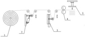
图1为本发明一种新型高速间歇牵引的张力控制方法的结构示意图;1 is a schematic structural diagram of a tension control method of a novel high-speed intermittent traction of the present invention;
图中:1、放卷机构;2、张力机构;3、张力储料机构;4、牵引辊机构;5、冲切装置。In the figure: 1. Unwinding mechanism; 2. Tension mechanism; 3. Tension storage mechanism; 4. Traction roller mechanism; 5. Punching device.
具体实施方式Detailed ways
为使本发明实现的技术手段、创作特征、达成目的与功效易于明白了解,下面结合具体实施方式,进一步阐述本发明。In order to make the technical means, creative features, achievement goals and effects realized by the present invention easy to understand, the present invention will be further described below with reference to the specific embodiments.
如图1所示,一种新型高速间歇牵引的张力控制方法,高速间歇牵引的张力控制组成具体结构为:放卷机构1、张力机构2、张力储料机构3、牵引辊机构4和冲切装置5,所述张力储料机构3由伺服电机、丝杆、缓冲辊、支架等部分组成,所述放卷机构1由放卷气涨轴、料卷、伺服电机、料卷测量传感器等组成,所述张力机构2由摆动辊、气缸、张力传感器等组成,所述牵引辊机构4由伺服电机、主动辊、被动辊、支架等部分组成,所述冲切装置5由伺服电机、凸轮机构、模架、模具组成。As shown in Figure 1, a new tension control method of high-speed intermittent traction, the specific structure of the tension control of high-speed intermittent traction is: unwinding mechanism 1, tension mechanism 2, tension storage mechanism 3, traction roller mechanism 4 and
具体按照以下步骤实施:Specifically, follow the steps below:
步骤一,开始工作之前,放卷机构1、张力储料机构3和牵引辊机构4以整机同步速度V运行,放料机构1的速度V0=V,张力储料机构3 的速度V1=V,张力储料机构3静止,张力储料机构3的速度V1=0,牵引辊机构4V2=V。Step 1: Before starting work, the unwinding mechanism 1, the tension storage mechanism 3 and the traction roller mechanism 4 run at the synchronous speed V of the whole machine, the speed of the unwinding mechanism 1 is V0=V, and the speed of the tension storage mechanism 3 is V1=V , the tension storage mechanism 3 is stationary, the speed of the tension storage mechanism 3 is V1=0, and the traction roller mechanism 4V2=V.
步骤二,正式工作时,牵引辊机构4由内部伺服电机驱动主动辊旋转,使得卷料向前送一个卷料的长度N,在输送过程中,当张力储料机构 3上的丝杆主动上升一个定量M,这时张力储料机构3上的缓冲辊提供的卷料长度为M*2,放卷机构1供料的长度为N-M*2,由于M<N,即为牵引辊机构4到放卷机构1之间卷料长度减少,张力机构2上的摆动辊上升,安装在张力机构2上的张力传感器将检测到的张力信号反馈用户控制端,经由PID运算,当检测到张力偏差越大,放卷速度V0越大,当张力偏差越小,放卷速度V0越小,即放卷速度V0等于牵引速度V2,冲切装置5上的模切伺服电机驱动凸轮机构产生的上下运动,完成极片的裁切成型。Step 2: During the official operation, the traction roller mechanism 4 is driven by the internal servo motor to rotate the active roller, so that the coil material is fed forward by a length N of the coil material. During the conveying process, when the lead screw on the tension storage mechanism 3 actively rises A quantitative M, at this time, the length of the coil provided by the buffer roller on the tension storage mechanism 3 is M*2, and the length of the material supplied by the unwinding mechanism 1 is N-M*2. Since M<N, it is the traction roller mechanism 4 to The length of the coil material between the unwinding mechanism 1 decreases, the swing roller on the tension mechanism 2 rises, and the tension sensor installed on the tension mechanism 2 feeds back the detected tension signal to the user control end. The larger the unwinding speed V0 is, the smaller the tension deviation is, the smaller the unwinding speed V0 is, that is, the unwinding speed V0 is equal to the traction speed V2, and the die-cutting servo motor on the
步骤二中,N<M*2,PID为张力修正速度控制量。In step 2, N<M*2, PID is the tension correction speed control amount.
步骤三,所述步骤二中,当张力储料机构3的速度V1减为0时,放料机构1的速度V0与牵引辊机构4V2也同时降到V1,即为V0=V1=V2=0, 整个工作过程结束。Step 3, in the second step, when the speed V1 of the tension storage mechanism 3 is reduced to 0, the speed V0 of the unwinding mechanism 1 and the pulling roller mechanism 4V2 are also reduced to V1 at the same time, that is, V0=V1=V2=0 , the whole working process is over.
综上所述,本发明在放料过程过程中,通过调整张力储物机构3上的丝杆上下的高度来调整张力的大小,当张力储物机构3上的丝杆上升或下降一个定量时,张力机构2上的摆动辊就会发生位置变化,安装在张力机构2上的张力传感器就会将检测到的张力信号发送给控制端,控制端经过PID运算,改变放卷速度,最终达到放卷速度与牵引速度一致,以此为冲切牵引过程中提供平稳的张力。To sum up, the present invention adjusts the size of the tension by adjusting the up and down heights of the screw rod on the tension storage mechanism 3 during the discharging process. When the screw rod on the tension storage mechanism 3 rises or falls by a certain amount , the position of the swinging roller on the tension mechanism 2 will change, and the tension sensor installed on the tension mechanism 2 will send the detected tension signal to the control terminal. The roll speed is consistent with the pulling speed, so as to provide a stable tension during the punching and pulling process.
以上显示和描述了本发明的基本原理和主要特征和本发明的优点,本行业的技术人员应该了解,本发明不受上述实施例的限制,上述实施例和说明书中描述的只是说明本发明的原理,在不脱离本发明精神和范围的前提下,本发明还会有各种变化和改进,这些变化和改进都落入要求保护的本发明范围内。本发明要求保护范围由所附的权利要求书及其等效物界定。The basic principles, main features and advantages of the present invention are shown and described above. Those skilled in the art should understand that the present invention is not limited by the above-mentioned embodiments, and the descriptions in the above-mentioned embodiments and the description are only for illustrating the present invention. In principle, without departing from the spirit and scope of the present invention, the present invention may have various changes and improvements, and these changes and improvements all fall within the scope of the claimed invention. The claimed scope of the present invention is defined by the appended claims and their equivalents.
Claims (1)
Priority Applications (1)
| Application Number | Priority Date | Filing Date | Title |
|---|---|---|---|
| CN202010310288.8A CN111908231A (en) | 2020-04-17 | 2020-04-17 | Novel tension control method for high-speed intermittent traction |
Applications Claiming Priority (1)
| Application Number | Priority Date | Filing Date | Title |
|---|---|---|---|
| CN202010310288.8A CN111908231A (en) | 2020-04-17 | 2020-04-17 | Novel tension control method for high-speed intermittent traction |
Publications (1)
| Publication Number | Publication Date |
|---|---|
| CN111908231A true CN111908231A (en) | 2020-11-10 |
Family
ID=73237542
Family Applications (1)
| Application Number | Title | Priority Date | Filing Date |
|---|---|---|---|
| CN202010310288.8A Withdrawn CN111908231A (en) | 2020-04-17 | 2020-04-17 | Novel tension control method for high-speed intermittent traction |
Country Status (1)
| Country | Link |
|---|---|
| CN (1) | CN111908231A (en) |
Cited By (12)
| Publication number | Priority date | Publication date | Assignee | Title |
|---|---|---|---|---|
| CN112794138A (en) * | 2021-01-15 | 2021-05-14 | 汕头东风印刷股份有限公司 | Double-traction mechanism and control method thereof |
| CN113183440A (en) * | 2021-04-28 | 2021-07-30 | 重庆科技学院 | Butyl rubber vibration damping belt production line and tension control method |
| CN113636384A (en) * | 2021-10-19 | 2021-11-12 | 佛山市天正机械有限公司 | Unreeling machine suitable for easily-stretched and deformed film material |
| CN113998511A (en) * | 2021-11-05 | 2022-02-01 | 深圳吉阳智能科技有限公司 | Speed reduction impact following V angle method and speed reduction impact following V angle device |
| CN114305870A (en) * | 2021-12-29 | 2022-04-12 | 福建恒安集团有限公司 | Production method of absorption core |
| CN115385157A (en) * | 2022-09-30 | 2022-11-25 | 湖南福瑞印刷有限公司 | Web and single sheet process connection production control system and method |
| CN116495553A (en) * | 2023-03-24 | 2023-07-28 | 安徽巨一科技股份有限公司 | A pole piece die-cutting, stacking and fusion system and control method |
| CN116765684A (en) * | 2023-05-31 | 2023-09-19 | 武汉逸飞激光股份有限公司 | A kind of pole piece seam welding equipment |
| CN116812611A (en) * | 2023-07-11 | 2023-09-29 | 常州晟威机电股份有限公司 | Film transmission mechanism based on film capacitor winding and unwinding |
| CN118062642A (en) * | 2024-04-19 | 2024-05-24 | 深圳市曼恩斯特科技股份有限公司 | Tension control system, method and pole piece production equipment |
| CN119531015A (en) * | 2024-08-30 | 2025-02-28 | 武汉纺织大学 | A spinning mechanism for core-spun yarn |
| CN120206054A (en) * | 2025-05-23 | 2025-06-27 | 广东亿鑫丰智能装备股份有限公司 | A high-speed laser die-cutting machine |
-
2020
- 2020-04-17 CN CN202010310288.8A patent/CN111908231A/en not_active Withdrawn
Cited By (16)
| Publication number | Priority date | Publication date | Assignee | Title |
|---|---|---|---|---|
| CN112794138A (en) * | 2021-01-15 | 2021-05-14 | 汕头东风印刷股份有限公司 | Double-traction mechanism and control method thereof |
| CN112794138B (en) * | 2021-01-15 | 2025-02-14 | 常州市华健药用包装材料有限公司 | Double traction mechanism and control method thereof |
| CN113183440A (en) * | 2021-04-28 | 2021-07-30 | 重庆科技学院 | Butyl rubber vibration damping belt production line and tension control method |
| CN113183440B (en) * | 2021-04-28 | 2023-01-24 | 重庆科技学院 | Butyl rubber vibration damping belt production line and tension control method |
| CN113636384A (en) * | 2021-10-19 | 2021-11-12 | 佛山市天正机械有限公司 | Unreeling machine suitable for easily-stretched and deformed film material |
| CN113998511B (en) * | 2021-11-05 | 2024-01-19 | 深圳吉阳智能科技有限公司 | Method for reducing speed and punching V angle and device for reducing speed and punching V angle |
| CN113998511A (en) * | 2021-11-05 | 2022-02-01 | 深圳吉阳智能科技有限公司 | Speed reduction impact following V angle method and speed reduction impact following V angle device |
| CN114305870A (en) * | 2021-12-29 | 2022-04-12 | 福建恒安集团有限公司 | Production method of absorption core |
| CN114305870B (en) * | 2021-12-29 | 2022-09-09 | 福建恒安集团有限公司 | Production method of absorption core |
| CN115385157A (en) * | 2022-09-30 | 2022-11-25 | 湖南福瑞印刷有限公司 | Web and single sheet process connection production control system and method |
| CN116495553A (en) * | 2023-03-24 | 2023-07-28 | 安徽巨一科技股份有限公司 | A pole piece die-cutting, stacking and fusion system and control method |
| CN116765684A (en) * | 2023-05-31 | 2023-09-19 | 武汉逸飞激光股份有限公司 | A kind of pole piece seam welding equipment |
| CN116812611A (en) * | 2023-07-11 | 2023-09-29 | 常州晟威机电股份有限公司 | Film transmission mechanism based on film capacitor winding and unwinding |
| CN118062642A (en) * | 2024-04-19 | 2024-05-24 | 深圳市曼恩斯特科技股份有限公司 | Tension control system, method and pole piece production equipment |
| CN119531015A (en) * | 2024-08-30 | 2025-02-28 | 武汉纺织大学 | A spinning mechanism for core-spun yarn |
| CN120206054A (en) * | 2025-05-23 | 2025-06-27 | 广东亿鑫丰智能装备股份有限公司 | A high-speed laser die-cutting machine |
Similar Documents
| Publication | Publication Date | Title |
|---|---|---|
| CN201796992U (en) | Rolling and slicing direct-connected device for lithium-ion battery polar pieces | |
| CN205114661U (en) | Vertical rewinding machine of cutting of two rolling axles | |
| CN206218912U (en) | The automatic roll-changing device of medical adhesive tape automatic wrapping machine | |
| CN203158889U (en) | Floating roller device of thin film production equipment | |
| CN101648223A (en) | Small self-adapting wire drawing machine with variable disk diameter | |
| CN201244903Y (en) | Floating roll apparatus of casting membrane set winding mechanism | |
| CN220148776U (en) | Following roller mechanism in film winding equipment | |
| CN107195982A (en) | A kind of closed-loop lithium battery core coil device and method | |
| CN101850485B (en) | Belt unreeling device | |
| CN106910865A (en) | Pole piece coiling device | |
| CN109895414B (en) | Casting machine with stable tension | |
| CN210312709U (en) | Automatic roll changing device that cuts of coating machine | |
| CN219832725U (en) | Winding equipment | |
| CN202293273U (en) | Vesicle stabilizer with adjustable vesicle contact degree for blow molding machine | |
| CN219924092U (en) | A coiler structure for controlling reel tension | |
| CN202967641U (en) | Underfeed non-shaft feeding machine frame set | |
| CN210390173U (en) | Casting machine with stable tension | |
| CN215943185U (en) | Rotary punching device for plastic film | |
| CN205932585U (en) | Membrane unwinding device | |
| CN208196926U (en) | Film splitter | |
| CN102311009B (en) | Active tension control method | |
| CN114455374A (en) | Method for controlling diaphragm feeding tension | |
| CN111857039B (en) | Multi-motor shearing system collaborative planning method and system | |
| CN217258203U (en) | Electric adjustment four-side extrusion foam stabilizing device | |
| CN116207323A (en) | High-speed winding deviation correcting device and deviation correcting method |
Legal Events
| Date | Code | Title | Description |
|---|---|---|---|
| PB01 | Publication | ||
| PB01 | Publication | ||
| WW01 | Invention patent application withdrawn after publication |
Application publication date: 20201110 |
|
| WW01 | Invention patent application withdrawn after publication |