CN111895831A - a heat exchange device - Google Patents
a heat exchange device Download PDFInfo
- Publication number
- CN111895831A CN111895831A CN202010797337.5A CN202010797337A CN111895831A CN 111895831 A CN111895831 A CN 111895831A CN 202010797337 A CN202010797337 A CN 202010797337A CN 111895831 A CN111895831 A CN 111895831A
- Authority
- CN
- China
- Prior art keywords
- box
- heat
- box body
- exchange device
- pipe
- Prior art date
- Legal status (The legal status is an assumption and is not a legal conclusion. Google has not performed a legal analysis and makes no representation as to the accuracy of the status listed.)
- Pending
Links
Images

Classifications
-
- F—MECHANICAL ENGINEERING; LIGHTING; HEATING; WEAPONS; BLASTING
- F28—HEAT EXCHANGE IN GENERAL
- F28D—HEAT-EXCHANGE APPARATUS, NOT PROVIDED FOR IN ANOTHER SUBCLASS, IN WHICH THE HEAT-EXCHANGE MEDIA DO NOT COME INTO DIRECT CONTACT
- F28D15/00—Heat-exchange apparatus with the intermediate heat-transfer medium in closed tubes passing into or through the conduit walls ; Heat-exchange apparatus employing intermediate heat-transfer medium or bodies
- F28D15/02—Heat-exchange apparatus with the intermediate heat-transfer medium in closed tubes passing into or through the conduit walls ; Heat-exchange apparatus employing intermediate heat-transfer medium or bodies in which the medium condenses and evaporates, e.g. heat pipes
- F28D15/0258—Heat-exchange apparatus with the intermediate heat-transfer medium in closed tubes passing into or through the conduit walls ; Heat-exchange apparatus employing intermediate heat-transfer medium or bodies in which the medium condenses and evaporates, e.g. heat pipes with means to remove contaminants, e.g. getters
-
- F—MECHANICAL ENGINEERING; LIGHTING; HEATING; WEAPONS; BLASTING
- F23—COMBUSTION APPARATUS; COMBUSTION PROCESSES
- F23J—REMOVAL OR TREATMENT OF COMBUSTION PRODUCTS OR COMBUSTION RESIDUES; FLUES
- F23J15/00—Arrangements of devices for treating smoke or fumes
- F23J15/06—Arrangements of devices for treating smoke or fumes of coolers
-
- F—MECHANICAL ENGINEERING; LIGHTING; HEATING; WEAPONS; BLASTING
- F28—HEAT EXCHANGE IN GENERAL
- F28F—DETAILS OF HEAT-EXCHANGE AND HEAT-TRANSFER APPARATUS, OF GENERAL APPLICATION
- F28F19/00—Preventing the formation of deposits or corrosion, e.g. by using filters or scrapers
- F28F19/02—Preventing the formation of deposits or corrosion, e.g. by using filters or scrapers by using coatings, e.g. vitreous or enamel coatings
-
- F—MECHANICAL ENGINEERING; LIGHTING; HEATING; WEAPONS; BLASTING
- F28—HEAT EXCHANGE IN GENERAL
- F28F—DETAILS OF HEAT-EXCHANGE AND HEAT-TRANSFER APPARATUS, OF GENERAL APPLICATION
- F28F27/00—Control arrangements or safety devices specially adapted for heat-exchange or heat-transfer apparatus
-
- Y—GENERAL TAGGING OF NEW TECHNOLOGICAL DEVELOPMENTS; GENERAL TAGGING OF CROSS-SECTIONAL TECHNOLOGIES SPANNING OVER SEVERAL SECTIONS OF THE IPC; TECHNICAL SUBJECTS COVERED BY FORMER USPC CROSS-REFERENCE ART COLLECTIONS [XRACs] AND DIGESTS
- Y02—TECHNOLOGIES OR APPLICATIONS FOR MITIGATION OR ADAPTATION AGAINST CLIMATE CHANGE
- Y02E—REDUCTION OF GREENHOUSE GAS [GHG] EMISSIONS, RELATED TO ENERGY GENERATION, TRANSMISSION OR DISTRIBUTION
- Y02E20/00—Combustion technologies with mitigation potential
- Y02E20/30—Technologies for a more efficient combustion or heat usage
Landscapes
- Engineering & Computer Science (AREA)
- Mechanical Engineering (AREA)
- General Engineering & Computer Science (AREA)
- Physics & Mathematics (AREA)
- Thermal Sciences (AREA)
- Life Sciences & Earth Sciences (AREA)
- Sustainable Development (AREA)
- Heat-Exchange Devices With Radiators And Conduit Assemblies (AREA)
Abstract
本发明涉及陶瓷生产领域,提供一种热交换装置,用于解决烟气中热量的回收利用问题。本发明提供的一种热交换装置,包括:冷源,所述冷源包括第一箱体和鼓风机,所述第一箱体同所述鼓风机连通;换热器,所述换热器包括第二箱体、热管、引风机,所述热管设置在第二箱体内,所述引风机同所述第二箱体连接,所述第二箱体同烟管连接;所述第二箱体同所述第一箱体连接,所述热管包括汽化段和液化段,所述液化段设置在所述第一箱体与所述第二箱体的连接处。充分利用了烟气中热量,同时不会将烟气中污染物质引入到冷源中,提高了能量利用效率,节省了陶瓷生产过程中水煤气的用量。
The invention relates to the field of ceramic production, and provides a heat exchange device for solving the problem of recycling heat in flue gas. A heat exchange device provided by the present invention includes: a cold source, the cold source includes a first box body and a blower, the first box body communicates with the blower; a heat exchanger, the heat exchanger includes a first box body and a blower. Two boxes, a heat pipe and an induced draft fan, the heat pipe is arranged in the second box, the induced draft fan is connected to the second box, the second box is connected to the smoke pipe; the second box is connected to the The first box is connected, the heat pipe includes a vaporization section and a liquefaction section, and the liquefaction section is arranged at the connection between the first box and the second box. The heat in the flue gas is fully utilized, and the pollutants in the flue gas are not introduced into the cold source, which improves the energy utilization efficiency and saves the consumption of water and gas in the ceramic production process.
Description
技术领域technical field
本发明涉及陶瓷生产领域,具体涉及一种热交换装置。The invention relates to the field of ceramic production, in particular to a heat exchange device.
背景技术Background technique
目前,随着国家对环保要求越来越高,大多数燃料烟气排放前都安装了烟气脱硫系统,国内采用的烟气脱硫系统中,由于湿法脱硫技术成熟,脱硫效率高,大部分采用的湿法脱硫。但为了保证烟气的脱硫效果,预脱硫烟气进入脱硫塔前要先进行降温处理,传统方法只考虑烟气脱硫,并未对烟气所携带的热量进行合理利用。At present, with the country's higher and higher requirements for environmental protection, most fuel flue gas is installed with a flue gas desulfurization system before being discharged. Among the flue gas desulfurization systems used in China, due to the mature wet desulfurization technology and high desulfurization efficiency, most of the flue gas desulfurization systems are used. Wet desulfurization used. However, in order to ensure the desulfurization effect of the flue gas, the pre-desulfurized flue gas must be cooled before entering the desulfurization tower. The traditional method only considers the flue gas desulfurization, and does not make reasonable use of the heat carried by the flue gas.
瓷砖生产的炉窑中产生的烟气温度可以达到400摄氏度以上,能量很高,现有技术利用率低,无法充分利用烟气中的能量。The temperature of the flue gas generated in the kiln for ceramic tile production can reach more than 400 degrees Celsius, and the energy is very high. The utilization rate of the existing technology is low, and the energy in the flue gas cannot be fully utilized.
发明内容SUMMARY OF THE INVENTION
本发明解决的技术问题为烟气中热量的回收利用问题,提供一种热交换装置。The technical problem solved by the invention is the problem of recycling and utilization of heat in flue gas, and a heat exchange device is provided.
为了解决上述技术问题,本发明提供的技术方案为:In order to solve the above-mentioned technical problems, the technical scheme provided by the present invention is:
一种热交换装置,包括:A heat exchange device, comprising:
冷源,所述冷源包括第一箱体和鼓风机,所述第一箱体同所述鼓风机连通;a cold source, the cold source includes a first box body and a blower, and the first box body communicates with the blower;
换热器,所述换热器包括第二箱体、热管、引风机,所述热管设置在第二箱体内,所述引风机同所述第二箱体连接,所述第二箱体同烟管连接;A heat exchanger, the heat exchanger includes a second box body, a heat pipe and an induced draft fan, the heat pipe is arranged in the second box body, the induced draft fan is connected to the second box body, and the second box body is connected to the second box body. smoke pipe connection;
所述第二箱体同所述第一箱体连接,所述热管包括汽化段和液化段,所述液化段设置在所述第一箱体与所述第二箱体的连接处。The second box is connected to the first box, the heat pipe includes a vaporization section and a liquefaction section, and the liquefaction section is arranged at the connection between the first box and the second box.
利用陶瓷生产过程中产生烟气的热量有一部分经换热器吸收后,传递给冷源,冷源中的空气受热后可用于陶瓷生产。Part of the heat generated by the flue gas in the ceramic production process is absorbed by the heat exchanger and then transferred to the cold source, and the air in the cold source can be used for ceramic production after being heated.
充分利用了烟气中热量,同时不会将烟气中污染物质引入到冷源中,提高了能量利用效率,节省了陶瓷生产过程中水煤气的用量。The heat in the flue gas is fully utilized, and the pollutants in the flue gas are not introduced into the cold source, which improves the energy utilization efficiency and saves the consumption of water and gas in the ceramic production process.
优选地,所述热管不少于一根,所述热管的所述汽化段分布在第二箱体内。Preferably, there is not less than one heat pipe, and the vaporization section of the heat pipe is distributed in the second box.
优选地,所述烟管内烟气的流量为15000~25000Nm3/h,所述烟气的温度为350~450℃。Preferably, the flow rate of the flue gas in the smoke pipe is 15000~25000Nm3/h, and the temperature of the flue gas is 350~450°C.
优选地,所述第一箱体内空气的流量为15000~20000Nm3/h,所述空气的温度为25~35℃。Preferably, the flow rate of the air in the first box is 15000~20000Nm3/h, and the temperature of the air is 25~35°C.
优选地,所述鼓风机同所述引风机电性连接,所述鼓风机停机后,所述引风机也需停机。Preferably, the blower is electrically connected with the induced draft fan, and after the blower is stopped, the induced draft fan also needs to be stopped.
优选地,所述第一箱体的空气入口处同所述鼓风机连接,所述第一箱体的空气出口处设置温度传感器和压力传感器。Preferably, the air inlet of the first box is connected to the blower, and the air outlet of the first box is provided with a temperature sensor and a pressure sensor.
优选地,所述烟管内设置有压力传感器,所述热管内设置有温度传感器。Preferably, a pressure sensor is arranged in the smoke pipe, and a temperature sensor is arranged in the heat pipe.
优选地,所述烟管同三通连接,所述三通包括进烟口、第一分流口和第二分流口,所述进烟口同所述烟管连接,所述第一分流口同所述第二箱体连接,所述第二分流口同蝶阀连接;Preferably, the cigarette pipe is connected with a tee, and the tee includes a smoke inlet, a first branch port and a second branch port, the smoke inlet is connected with the smoke pipe, and the first branch port is the same as the smoke pipe. the second box is connected, and the second split port is connected with the butterfly valve;
所述蝶阀的开度为50~80%。The opening degree of the butterfly valve is 50-80%.
优选地,所述第二箱体上设置有检修口。Preferably, an inspection port is provided on the second box body.
优选地,所述第二箱体上设置有灰斗。Preferably, an ash hopper is provided on the second box body.
优选地,所述热管上涂覆有自清洁涂层。Preferably, the heat pipe is coated with a self-cleaning coating.
优选地,所述自清洁涂层由自清洁涂料涂覆到热管上形成;所述自清洁涂料的制备方法为:Preferably, the self-cleaning coating is formed by applying a self-cleaning coating to the heat pipe; the preparation method of the self-cleaning coating is:
取聚四氟乙烯树脂20~25质量份,聚醚砜树脂5~10质量份,改性纳米二氧化硅5~10质量份,改性纳米二氧化钛5~10质量份,分散剂0.5~1质量份,消泡剂0.5~1质量份,流平剂0.5~1质量份,二甲苯100~120质量份;Take 20-25 parts by mass of polytetrafluoroethylene resin, 5-10 parts by mass of polyethersulfone resin, 5-10 parts by mass of modified nano-silicon dioxide, 5-10 parts by mass of modified nano-titanium dioxide, and 0.5-1 part by mass of dispersant parts, 0.5-1 part by mass of defoamer, 0.5-1 part by mass of leveling agent, and 100-120 parts by mass of xylene;
将聚醚砜树脂加入二甲苯中,加热搅拌溶解均匀,加入改性纳米二氧化硅、改性纳米二氧化钛、消泡剂、流平剂、分散剂,至于球磨机中球磨36h,将球磨得到的浆料与聚四氟乙烯树脂粉搅拌混合均匀,过筛,得到自清洁涂料。Add polyethersulfone resin into xylene, heat and stir to dissolve evenly, add modified nano-silicon dioxide, modified nano-titanium dioxide, defoaming agent, leveling agent, dispersing agent, as for ball milling in a ball mill for 36 hours, the slurry obtained by ball milling The material and polytetrafluoroethylene resin powder are stirred and mixed evenly, and sieved to obtain a self-cleaning coating.
优选的,所述改性纳米二氧化硅的制备方法为:将水玻璃的饱和溶液与碳酸氢钠的饱和溶液按1:1的体积比混合,加热至90摄氏度,充分搅拌1h,得到硅溶胶,加入硝酸银溶液进行离子交换反应,反应完成后洗涤干燥,得到改性纳米二氧化硅。Preferably, the preparation method of the modified nano-silica is as follows: mixing a saturated solution of water glass and a saturated solution of sodium bicarbonate in a volume ratio of 1:1, heating to 90 degrees Celsius, and fully stirring for 1 hour to obtain a silica sol , adding silver nitrate solution to carry out ion exchange reaction, washing and drying after the reaction is completed to obtain modified nano-silica.
优选地,所述改性纳米二氧化钛的制备方法:Preferably, the preparation method of the modified nano titanium dioxide:
取木质素环酸盐10~15质量份,烷基三甲基溴化铵2~4质量份,钛酸丁酯10~20质量份,乙醇100~200质量份;Take 10-15 parts by mass of lignin cyclic acid salt, 2-4 parts by mass of alkyl trimethyl ammonium bromide, 10-20 parts by mass of butyl titanate, and 100-200 parts by mass of ethanol;
将木质素磺酸盐和烷基三甲基溴化铵分别配置成2g/L的溶液,混合均匀,分离沉淀物,干燥,得到第一产物;The lignosulfonate and the alkyl trimethyl ammonium bromide are respectively configured into a 2g/L solution, mixed evenly, the precipitate is separated, and dried to obtain the first product;
将钛酸丁酯与乙醇混合,加入第一产物,搅拌均匀,缓慢滴加到pH为5的水中,水的用量是乙醇体积的3倍,搅拌40min,将混合液离心、洗涤后,在80摄氏度下干燥4h,得到的固体研磨后在氮气气氛中500摄氏度煅烧2h,冷却至室温,得到改性纳米二氧化钛。Mix butyl titanate and ethanol, add the first product, stir evenly, slowly add dropwise to water with a pH of 5, the amount of water is 3 times the volume of ethanol, stir for 40 min, centrifuge and wash the mixture, and put it at 80 After drying at degrees Celsius for 4 hours, the obtained solid was ground and calcined at 500 degrees Celsius for 2 hours in a nitrogen atmosphere, and cooled to room temperature to obtain modified nano-titanium dioxide.
与现有技术相比,本发明具有的有益效果为:充分利用了烟气中热量,同时不会将烟气中污染物质引入到冷源中,提高了能量利用效率,节省了陶瓷生产过程中水煤气的用量。Compared with the prior art, the present invention has the beneficial effects of fully utilizing the heat in the flue gas, without introducing the pollutants in the flue gas into the cold source, improving the energy utilization efficiency and saving the time in the ceramic production process. The amount of water and gas.
冷源中空气可以被加热到200摄氏度以上,满足陶瓷生产过程的需要,大幅节约了能源。The air in the cold source can be heated to more than 200 degrees Celsius, which meets the needs of the ceramic production process and greatly saves energy.
附图说明Description of drawings
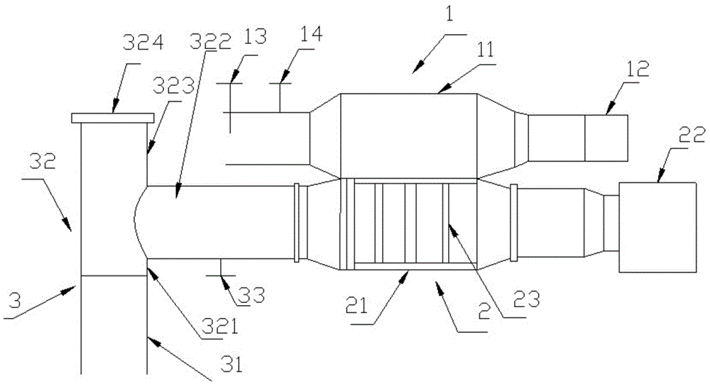
图1为一种热交换装置的示意图。FIG. 1 is a schematic diagram of a heat exchange device.
具体实施方式Detailed ways
以下实施例是对本发明的进一步说明,不是对本发明的限制。The following examples are to further illustrate the present invention, but not to limit the present invention.
实施例1Example 1
一种热交换装置,包括:A heat exchange device, comprising:
冷源1,所述冷源1包括第一箱体11和鼓风机12,所述第一箱体11同所述鼓风机12连通;
换热器2,所述换热器2包括第二箱体21、热管23、引风机22,所述热管23设置在第二箱体21内,所述引风机22同所述第二箱体21连接,所述第二箱体21同烟管3连接;Heat exchanger 2. The heat exchanger 2 includes a
所述第二箱体21同所述第一箱体11连接,所述热管23包括汽化段和液化段,所述液化段设置在所述第一箱体11与所述第二箱体21的连接处。所述热管23不少于一根,所述热管23的所述汽化段分布在第二箱体21内。所述烟管3内烟气的流量为15000~25000Nm3/h,所述烟气的温度为350~450℃。所述第一箱体11内空气的流量为15000~20000Nm3/h,所述空气的温度为25~35℃。所述鼓风机12同所述引风机22电性连接,所述鼓风机12停机后,所述引风机22也需停机。所述第一箱体11的空气入口处同所述鼓风机12连接,所述第一箱体11的空气出口处设置温度传感器13和压力传感器14。所述烟管内设置有压力传感器33,所述热管内设置有温度传感器。所述烟管3包括输送管31和三通32,所述输送管31同三通32连接,所述三通32包括进烟口321、第一分流口322和第二分流口323,所述进烟口321同所述输送管31连接,所述第一分流口322同所述第二箱体21连接,所述第二分流口323同蝶阀324连接;The
所述蝶阀324的开度为50~80%。所述第二箱体21上设置有检修口。The opening degree of the
利用陶瓷生产过程中产生烟气的热量有一部分经换热器吸收后,传递给冷源,冷源中的空气受热后可用于陶瓷生产。充分利用了烟气中热量,同时不会将烟气中污染物质引入到冷源中,提高了能量利用效率,节省了陶瓷生产过程中水煤气的用量。Part of the heat generated by the flue gas in the ceramic production process is absorbed by the heat exchanger and then transferred to the cold source, and the air in the cold source can be used for ceramic production after being heated. The heat in the flue gas is fully utilized, and the pollutants in the flue gas are not introduced into the cold source, which improves the energy utilization efficiency and saves the consumption of water and gas in the ceramic production process.
实施例2Example 2
一种热交换装置,包括:A heat exchange device, comprising:
冷源1,所述冷源1包括第一箱体11和鼓风机12,所述第一箱体11同所述鼓风机12连通;
换热器2,所述换热器2包括第二箱体21、热管23、引风机22,所述热管23设置在第二箱体21内,所述引风机22同所述第二箱体21连接,所述第二箱体21同烟管3连接;Heat exchanger 2. The heat exchanger 2 includes a
所述第二箱体21同所述第一箱体11连接,所述热管23包括汽化段和液化段,所述汽化段分布在所述第二箱体21内。所述热管23不少于一根,所述热管23的所述液化段穿过所述第一箱体11和第二箱体12的箱壁进入第一箱体11中。所述烟管3内烟气的流量为15000~25000Nm3/h,所述烟气的温度为350~450℃。所述第一箱体11内空气的流量为15000~20000Nm3/h,所述空气的温度为25~35℃。所述鼓风机12同所述引风机22电性连接,所述鼓风机12停机后,所述引风机22也需停机。所述第一箱体11的空气入口处同所述鼓风机12连接,所述第一箱体11的空气出口处设置温度传感器13和压力传感器14。所述烟管内设置有压力传感器33,所述热管内设置有温度传感器。所述烟管3包括输送管31和三通32,所述输送管31同三通32连接,所述三通32包括进烟口321、第一分流口322和第二分流口323,所述进烟口321同所述输送管31连接,所述第一分流口322同所述第二箱体21连接,所述第二分流口323同蝶阀324连接;The
所述蝶阀324的开度为50~80%。所述第二箱体21上设置有检修口。The opening degree of the
实施例3Example 3
实施例3同实施例1不同之处在于,所述热管上涂覆有自清洁涂层,所述自清洁涂层由自清洁涂料涂覆到热管上形成;所述自清洁涂料的制备方法为:The difference between Example 3 and Example 1 is that the heat pipe is coated with a self-cleaning coating, and the self-cleaning coating is formed by applying the self-cleaning coating to the heat pipe; the preparation method of the self-cleaning coating is as follows. :
取聚四氟乙烯树脂22Kg,聚醚砜树脂6Kg,改性纳米二氧化硅7量份,改性纳米二氧化钛6Kg,分散剂0.6Kg,消泡剂0.7Kg,流平剂0.7Kg,二甲苯110Kg;Take 22Kg of polytetrafluoroethylene resin, 6Kg of polyethersulfone resin, 7 parts of modified nano-silica, 6Kg of modified nano-titanium dioxide, 0.6Kg of dispersant, 0.7Kg of defoamer, 0.7Kg of leveling agent, and 110Kg of xylene ;
将聚醚砜树脂加入二甲苯中,加热搅拌溶解均匀,加入改性纳米二氧化硅、改性纳米二氧化钛、消泡剂、流平剂、分散剂,至于球磨机中球磨36h,将球磨得到的浆料与聚四氟乙烯树脂粉搅拌混合均匀,过筛,得到自清洁涂料。Add polyethersulfone resin into xylene, heat and stir to dissolve evenly, add modified nano-silicon dioxide, modified nano-titanium dioxide, defoaming agent, leveling agent, dispersing agent, as for ball milling in a ball mill for 36 hours, the slurry obtained by ball milling The material and polytetrafluoroethylene resin powder are stirred and mixed evenly, and sieved to obtain a self-cleaning coating.
所述改性纳米二氧化硅的制备方法为:将水玻璃的饱和溶液与碳酸氢钠的饱和溶液按1:1的体积比混合,加热至90摄氏度,充分搅拌1h,得到硅溶胶,加入硝酸银溶液进行离子交换反应,反应完成后洗涤干燥,得到改性纳米二氧化硅。The preparation method of the modified nano-silica is as follows: mixing a saturated solution of water glass and a saturated solution of sodium bicarbonate in a volume ratio of 1:1, heating to 90 degrees Celsius, fully stirring for 1 hour to obtain silica sol, adding nitric acid The silver solution is subjected to ion exchange reaction, and after the reaction is completed, it is washed and dried to obtain modified nano-silica.
所述改性纳米二氧化钛的制备方法:The preparation method of described modified nano titanium dioxide:
取木质素环酸盐6Kg,烷基三甲基溴化铵1.5Kg,钛酸丁酯6Kg,乙醇50Kg;Take lignin cyclate 6Kg, alkyl trimethylammonium bromide 1.5Kg, butyl titanate 6Kg, ethanol 50Kg;
将木质素磺酸盐和烷基三甲基溴化铵分别配置成2g/L的溶液,混合均匀,分离沉淀物,干燥,得到第一产物;The lignosulfonate and the alkyl trimethyl ammonium bromide are respectively configured into a 2g/L solution, mixed evenly, the precipitate is separated, and dried to obtain the first product;
将钛酸丁酯与乙醇混合,加入第一产物,搅拌均匀,缓慢滴加到pH为5的水中,水的用量是乙醇体积的3倍,搅拌40min,将混合液离心、洗涤后,在80摄氏度下干燥4h,得到的固体研磨后在氮气气氛中500摄氏度煅烧2h,冷却至室温,得到改性纳米二氧化钛。Mix butyl titanate and ethanol, add the first product, stir evenly, slowly drop into water with a pH of 5, the amount of water is 3 times the volume of ethanol, stir for 40 min, centrifuge and wash the mixture, and put it at 80 After drying at degrees Celsius for 4 hours, the obtained solid was ground and calcined at 500 degrees Celsius for 2 hours in a nitrogen atmosphere, and cooled to room temperature to obtain modified nano-titanium dioxide.
实施例4Example 4
实施例4同实施例2不同之处在于,所述热管上涂覆有自清洁涂层,所述自清洁涂层由自清洁涂料涂覆到热管上形成;所述自清洁涂料的制备方法为:The difference between Example 4 and Example 2 is that the heat pipe is coated with a self-cleaning coating, and the self-cleaning coating is formed by applying the self-cleaning coating to the heat pipe; the preparation method of the self-cleaning coating is as follows. :
取聚四氟乙烯树脂11Kg,聚醚砜树脂3Kg,改性纳米二氧化硅3.5量份,改性纳米二氧化钛3Kg,分散剂0.3Kg,消泡剂0.35Kg,流平剂0.35Kg,二甲苯55Kg;Take 11Kg of polytetrafluoroethylene resin, 3Kg of polyethersulfone resin, 3.5 parts of modified nano-silica, 3Kg of modified nano-titanium dioxide, 0.3Kg of dispersant, 0.35Kg of defoamer, 0.35Kg of leveling agent, and 55Kg of xylene ;
将聚醚砜树脂加入二甲苯中,加热搅拌溶解均匀,加入改性纳米二氧化硅、改性纳米二氧化钛、消泡剂、流平剂、分散剂,至于球磨机中球磨36h,将球磨得到的浆料与聚四氟乙烯树脂粉搅拌混合均匀,过筛,得到自清洁涂料。Add polyethersulfone resin into xylene, heat and stir to dissolve evenly, add modified nano-silicon dioxide, modified nano-titanium dioxide, defoaming agent, leveling agent, dispersing agent, as for ball milling in a ball mill for 36 hours, the slurry obtained by ball milling The material and polytetrafluoroethylene resin powder are stirred and mixed evenly, and sieved to obtain a self-cleaning coating.
所述改性纳米二氧化硅的制备方法为:将水玻璃的饱和溶液与碳酸氢钠的饱和溶液按1:1的体积比混合,加热至90摄氏度,充分搅拌1h,得到硅溶胶,加入硝酸银溶液进行离子交换反应,反应完成后洗涤干燥,得到改性纳米二氧化硅。The preparation method of the modified nano-silica is as follows: mixing a saturated solution of water glass and a saturated solution of sodium bicarbonate in a volume ratio of 1:1, heating to 90 degrees Celsius, fully stirring for 1 hour to obtain silica sol, adding nitric acid The silver solution is subjected to ion exchange reaction, and after the reaction is completed, it is washed and dried to obtain modified nano-silica.
所述改性纳米二氧化钛的制备方法:The preparation method of described modified nano titanium dioxide:
取木质素环酸盐3Kg,烷基三甲基溴化铵0.75Kg,钛酸丁酯3Kg,乙醇25Kg;Take 3Kg of lignin cyclic salt, 0.75Kg of alkyl trimethyl ammonium bromide, 3Kg of butyl titanate, and 25Kg of ethanol;
将木质素磺酸盐和烷基三甲基溴化铵分别配置成2g/L的溶液,混合均匀,分离沉淀物,干燥,得到第一产物;The lignosulfonate and the alkyl trimethyl ammonium bromide are respectively configured into a 2g/L solution, mixed evenly, the precipitate is separated, and dried to obtain the first product;
将钛酸丁酯与乙醇混合,加入第一产物,搅拌均匀,缓慢滴加到pH为5的水中,水的用量是乙醇体积的3倍,搅拌40min,将混合液离心、洗涤后,在80摄氏度下干燥4h,得到的固体研磨后在氮气气氛中500摄氏度煅烧2h,冷却至室温,得到改性纳米二氧化钛。Mix butyl titanate and ethanol, add the first product, stir evenly, slowly add dropwise to water with a pH of 5, the amount of water is 3 times the volume of ethanol, stir for 40 min, centrifuge and wash the mixture, and put it at 80 After drying at degrees Celsius for 4 hours, the obtained solid was ground and calcined at 500 degrees Celsius for 2 hours in a nitrogen atmosphere, and cooled to room temperature to obtain modified nano-titanium dioxide.
定期清洗实施例1~4中的热交换装置的热管,评价不同清洗周期对换热效率的影响。The heat pipes of the heat exchange devices in Examples 1 to 4 were cleaned regularly, and the effects of different cleaning cycles on the heat exchange efficiency were evaluated.
清洗方式为:The cleaning method is:
准备好高压清洗枪并接好水源。Have your pressure washer gun ready and connected to the water source.
手动打开脱硫主管蝶阀,使其处于全开状态。Manually open the butterfly valve of the main desulfurization and keep it fully open.
关闭换热器下层进口及引风机出口闸阀,把引风机及鼓风机频率降至最低安全频率。Close the lower inlet of the heat exchanger and the outlet gate valve of the induced draft fan, and reduce the frequency of the induced draft fan and the blower to the minimum safe frequency.
等换热器温度低于150度后,打开换热器两边侧门及污水出口。After the temperature of the heat exchanger is lower than 150 degrees, open the side doors on both sides of the heat exchanger and the sewage outlet.
直接用高压水枪冲洗器内热管。Directly flush the inner heat pipe with a high-pressure water gun.
实施例1中的换热器每隔1个月进行清洗,清洗后,冷源内空气最高温度可以达到210摄氏度;20天后,冷源内空气最高温度为190摄氏度;清洗前,冷源内最高温度可以达到180摄氏度。The heat exchanger in Example 1 is cleaned every 1 month. After cleaning, the maximum temperature of the air in the cold source can reach 210 degrees Celsius; 20 days later, the maximum temperature of the air in the cold source is 190 degrees Celsius; Before cleaning, the maximum temperature in the cold source can reach 210 degrees Celsius. 180 degrees Celsius.
实施例2中的换热器每隔1个月进行清洗,清洗后,冷源内空气最高温度可以达到215摄氏度;20天后,冷源内空气最高温度为190摄氏度;清洗前,冷源内最高温度可以达到186摄氏度。The heat exchanger in Example 2 is cleaned every 1 month. After cleaning, the maximum temperature of the air in the cold source can reach 215 degrees Celsius; 20 days later, the maximum temperature of the air in the cold source is 190 degrees Celsius; Before cleaning, the maximum temperature in the cold source can reach 215 degrees Celsius. 186 degrees Celsius.
实施例3中的换热器每隔2个月进行清洗,清洗后,冷源内空气最高温度可以达到212摄氏度;20天后,冷源内空气最高温度为203摄氏度;清洗前,冷源内最高温度可以达到201摄氏度。The heat exchanger in Example 3 is cleaned every 2 months. After cleaning, the maximum air temperature in the cold source can reach 212 degrees Celsius; 20 days later, the maximum air temperature in the cold source is 203 degrees Celsius; Before cleaning, the maximum temperature in the cold source can reach 212 degrees Celsius. 201 degrees Celsius.
实施例4中换热器每隔2个月进行清洗,清洗后,冷源内空气最高温度可以达到215摄氏度;20天后,冷源内空气最高温度为208摄氏度;清洗前,冷源内最高温度可以达到205摄氏度。In Example 4, the heat exchanger is cleaned every 2 months. After cleaning, the maximum air temperature in the cold source can reach 215 degrees Celsius; 20 days later, the maximum air temperature in the cold source is 208 degrees Celsius; Before cleaning, the maximum temperature in the cold source can reach 205 degrees Celsius. Celsius.
上列详细说明是针对本发明可行实施例的具体说明,以上实施例并非用以限制本发明的专利范围,凡未脱离本发明所为的等效实施或变更,均应包含于本案的专利范围中。The above detailed descriptions are specific descriptions of feasible embodiments of the present invention, and the above embodiments are not intended to limit the scope of the invention. middle.
Claims (10)
Priority Applications (1)
| Application Number | Priority Date | Filing Date | Title |
|---|---|---|---|
| CN202010797337.5A CN111895831A (en) | 2020-08-10 | 2020-08-10 | a heat exchange device |
Applications Claiming Priority (1)
| Application Number | Priority Date | Filing Date | Title |
|---|---|---|---|
| CN202010797337.5A CN111895831A (en) | 2020-08-10 | 2020-08-10 | a heat exchange device |
Publications (1)
| Publication Number | Publication Date |
|---|---|
| CN111895831A true CN111895831A (en) | 2020-11-06 |
Family
ID=73246923
Family Applications (1)
| Application Number | Title | Priority Date | Filing Date |
|---|---|---|---|
| CN202010797337.5A Pending CN111895831A (en) | 2020-08-10 | 2020-08-10 | a heat exchange device |
Country Status (1)
| Country | Link |
|---|---|
| CN (1) | CN111895831A (en) |
Citations (7)
| Publication number | Priority date | Publication date | Assignee | Title |
|---|---|---|---|---|
| WO1982001476A1 (en) * | 1980-10-23 | 1982-05-13 | Peter F Way | Apparatus for the recovery of vaporized phthalic anhydride from gas streams |
| CN101000175A (en) * | 2006-12-17 | 2007-07-18 | 崔付林 | Low temp. afterheat recovery type heat pipe boiler |
| CN102444901A (en) * | 2011-11-30 | 2012-05-09 | 辽宁赛沃斯节能技术有限公司 | Coal power plant combined type heat pipe flue gas waste heat recovery system and method |
| CN202338915U (en) * | 2011-11-30 | 2012-07-18 | 辽宁赛沃斯节能技术有限公司 | Corrosion-resisting heat pipe flue gas waste heat recovery system of coal power plant |
| CN206831545U (en) * | 2017-05-24 | 2018-01-02 | 新疆思凯压力容器制造有限公司 | Flue gas waste heat recovery apparatus |
| CN209371290U (en) * | 2018-12-11 | 2019-09-10 | 北京博惠通科技发展有限公司 | A kind of flue gas deep treatment and waste-heat recovery device based on heat pipe heat exchanging technology |
| CN212362930U (en) * | 2020-08-10 | 2021-01-15 | 广东欧文莱陶瓷有限公司 | a heat exchange device |
-
2020
- 2020-08-10 CN CN202010797337.5A patent/CN111895831A/en active Pending
Patent Citations (7)
| Publication number | Priority date | Publication date | Assignee | Title |
|---|---|---|---|---|
| WO1982001476A1 (en) * | 1980-10-23 | 1982-05-13 | Peter F Way | Apparatus for the recovery of vaporized phthalic anhydride from gas streams |
| CN101000175A (en) * | 2006-12-17 | 2007-07-18 | 崔付林 | Low temp. afterheat recovery type heat pipe boiler |
| CN102444901A (en) * | 2011-11-30 | 2012-05-09 | 辽宁赛沃斯节能技术有限公司 | Coal power plant combined type heat pipe flue gas waste heat recovery system and method |
| CN202338915U (en) * | 2011-11-30 | 2012-07-18 | 辽宁赛沃斯节能技术有限公司 | Corrosion-resisting heat pipe flue gas waste heat recovery system of coal power plant |
| CN206831545U (en) * | 2017-05-24 | 2018-01-02 | 新疆思凯压力容器制造有限公司 | Flue gas waste heat recovery apparatus |
| CN209371290U (en) * | 2018-12-11 | 2019-09-10 | 北京博惠通科技发展有限公司 | A kind of flue gas deep treatment and waste-heat recovery device based on heat pipe heat exchanging technology |
| CN212362930U (en) * | 2020-08-10 | 2021-01-15 | 广东欧文莱陶瓷有限公司 | a heat exchange device |
Non-Patent Citations (1)
| Title |
|---|
| 崔玉民: "绿色环保功能涂料", 31 January 2019, 中国书籍出版社, pages: 191 - 195 * |
Similar Documents
| Publication | Publication Date | Title |
|---|---|---|
| CN103193305B (en) | Drying production method and device for polyaluminium chloride water purifying agent | |
| CN105509492B (en) | A kind of Alumina Rotary Kiln fume afterheat and CO2 recovery systems and method | |
| CN102863061B (en) | Drying energy-saving method and device for producing polyaluminium chloride water purifying agent | |
| CN212362930U (en) | a heat exchange device | |
| CN102923719B (en) | For the waste heat recovery system of drying tail gas of white carbon black production | |
| CN201768448U (en) | Bag-type dust collector | |
| CN106215678B (en) | A cement kiln semi-dry desulfurization system | |
| CN210473593U (en) | Cement plant kiln tail flue gas cooling desulfurization increase system | |
| CN209934427U (en) | Energy-saving and environment-friendly nitrogen oxide emission reduction device for gas furnace | |
| CN203704683U (en) | Cleaning device used for maintaining furnace body pressure and realizing industrial waste gas and dust purification | |
| CN2670888Y (en) | Waste heat recovering and using system for annular brick kiln | |
| CN215995631U (en) | Spray drying tower entry air current equipartition structure and spray drying system | |
| CN209877487U (en) | A coal mill pipeline drying system | |
| CN207850097U (en) | A kind of reuse means of rotary kiln exhaust gas waste heat | |
| CN106196922A (en) | A kind of mercury catalyst switch type hot-air drying stove | |
| CN109624134A (en) | A kind of butadiene-styrene rubber drying device and drying means reducing discharge amount of exhaust gas | |
| CN223726819U (en) | A system for preparing fine powder slurry | |
| CN106440841A (en) | Exhaust gas recovery system for rotary kiln | |
| CN207313136U (en) | A kind of waste heat recycling system | |
| CN207850007U (en) | A kind of dry kiln heating system of dry laterite | |
| CN206724469U (en) | A kind of device for flue gas conversion heating thermal cycle | |
| CN205109559U (en) | Waste heat recovery formula spray granulation system | |
| CN222427161U (en) | Energy-saving mud drying device | |
| CN221706131U (en) | Reduce phosphorus compound fertilizer drying system of gas quantity | |
| CN216282800U (en) | Inlet flow-collecting type high-air energy-saving circulating air supply device |
Legal Events
| Date | Code | Title | Description |
|---|---|---|---|
| PB01 | Publication | ||
| PB01 | Publication | ||
| SE01 | Entry into force of request for substantive examination | ||
| SE01 | Entry into force of request for substantive examination | ||
| RJ01 | Rejection of invention patent application after publication | ||
| RJ01 | Rejection of invention patent application after publication |
Application publication date: 20201106 |