CN111889555A - Reciprocal quick production processingequipment of square board - Google Patents
Reciprocal quick production processingequipment of square board Download PDFInfo
- Publication number
- CN111889555A CN111889555A CN202010690050.2A CN202010690050A CN111889555A CN 111889555 A CN111889555 A CN 111889555A CN 202010690050 A CN202010690050 A CN 202010690050A CN 111889555 A CN111889555 A CN 111889555A
- Authority
- CN
- China
- Prior art keywords
- matching
- reciprocating
- gear
- welded
- processing
- Prior art date
- Legal status (The legal status is an assumption and is not a legal conclusion. Google has not performed a legal analysis and makes no representation as to the accuracy of the status listed.)
- Withdrawn
Links
- 238000004519 manufacturing process Methods 0.000 title claims abstract description 21
- 238000003754 machining Methods 0.000 claims abstract description 14
- 238000013016 damping Methods 0.000 claims description 30
- 239000000463 material Substances 0.000 claims description 26
- 230000008093 supporting effect Effects 0.000 claims description 22
- 238000009795 derivation Methods 0.000 claims description 18
- 230000006835 compression Effects 0.000 claims description 17
- 238000007906 compression Methods 0.000 claims description 17
- 238000003825 pressing Methods 0.000 claims description 17
- 238000006243 chemical reaction Methods 0.000 claims description 14
- 238000003466 welding Methods 0.000 claims description 3
- 238000004080 punching Methods 0.000 abstract description 11
- 229910052751 metal Inorganic materials 0.000 abstract description 4
- 239000002184 metal Substances 0.000 abstract description 4
- 238000000034 method Methods 0.000 description 9
- 230000008569 process Effects 0.000 description 9
- 230000006378 damage Effects 0.000 description 4
- 229910000838 Al alloy Inorganic materials 0.000 description 2
- RYGMFSIKBFXOCR-UHFFFAOYSA-N Copper Chemical compound [Cu] RYGMFSIKBFXOCR-UHFFFAOYSA-N 0.000 description 2
- 229910052802 copper Inorganic materials 0.000 description 2
- 239000010949 copper Substances 0.000 description 2
- 238000006073 displacement reaction Methods 0.000 description 2
- 230000000694 effects Effects 0.000 description 2
- 238000005381 potential energy Methods 0.000 description 2
- 238000007493 shaping process Methods 0.000 description 2
- 239000010935 stainless steel Substances 0.000 description 2
- 229910001220 stainless steel Inorganic materials 0.000 description 2
- 208000027418 Wounds and injury Diseases 0.000 description 1
- 230000009471 action Effects 0.000 description 1
- 239000004411 aluminium Substances 0.000 description 1
- 229910052782 aluminium Inorganic materials 0.000 description 1
- XAGFODPZIPBFFR-UHFFFAOYSA-N aluminium Chemical compound [Al] XAGFODPZIPBFFR-UHFFFAOYSA-N 0.000 description 1
- 230000009286 beneficial effect Effects 0.000 description 1
- 230000005540 biological transmission Effects 0.000 description 1
- 230000008602 contraction Effects 0.000 description 1
- 238000007599 discharging Methods 0.000 description 1
- 230000005489 elastic deformation Effects 0.000 description 1
- 230000001771 impaired effect Effects 0.000 description 1
- 208000014674 injury Diseases 0.000 description 1
- 230000003993 interaction Effects 0.000 description 1
- 238000012986 modification Methods 0.000 description 1
- 230000004048 modification Effects 0.000 description 1
- 230000001105 regulatory effect Effects 0.000 description 1
- 238000005096 rolling process Methods 0.000 description 1
Images




Classifications
-
- B—PERFORMING OPERATIONS; TRANSPORTING
- B21—MECHANICAL METAL-WORKING WITHOUT ESSENTIALLY REMOVING MATERIAL; PUNCHING METAL
- B21D—WORKING OR PROCESSING OF SHEET METAL OR METAL TUBES, RODS OR PROFILES WITHOUT ESSENTIALLY REMOVING MATERIAL; PUNCHING METAL
- B21D22/00—Shaping without cutting, by stamping, spinning, or deep-drawing
- B21D22/02—Stamping using rigid devices or tools
-
- B—PERFORMING OPERATIONS; TRANSPORTING
- B21—MECHANICAL METAL-WORKING WITHOUT ESSENTIALLY REMOVING MATERIAL; PUNCHING METAL
- B21D—WORKING OR PROCESSING OF SHEET METAL OR METAL TUBES, RODS OR PROFILES WITHOUT ESSENTIALLY REMOVING MATERIAL; PUNCHING METAL
- B21D55/00—Safety devices protecting the machine or the operator, specially adapted for apparatus or machines dealt with in this subclass
Landscapes
- Engineering & Computer Science (AREA)
- Mechanical Engineering (AREA)
- Presses And Accessory Devices Thereof (AREA)
Abstract
The invention relates to the technical field of metal plate processing, in particular to a reciprocating rapid production and processing device for square plates. The hydraulic push rod cylinder machining device comprises a machining carrying platform, wherein a plurality of feeding auxiliary wheels are fixed at the top end of the machining carrying platform, a positioning plate is welded at one end of the upper surface of the machining carrying platform, and a hydraulic push rod cylinder is fixed at one end of the positioning plate through a screw. According to the invention, through the design of the reciprocating punch forming structure, the device is convenient to achieve stable lifting frequency through gear matching conduction, and the matching design is counteracted by utilizing the return force, so that the forming punching efficiency of forming production, the uniformity of a formed outer pipe and the good service life are ensured.
Description
Technical Field
The invention relates to the technical field of metal plate processing, in particular to a reciprocating rapid production and processing device for square plates.
Background
The material kind of metal decorative board has aluminium, copper, stainless steel, aluminum alloy etc., select copper, stainless steel's decorative board grade is higher, the price is also high, general room is decorated, it is more suitable to select the aluminum alloy decorative board, current metal decorative board is mostly square board, corresponding square board processingequipment has appeared for the ease of machine-shaping, however, current device often receives the design restriction of deriving stamping structure in the production course of working, be not convenient for stable and quick uniform shaping, receive the counter-force injury easily, lead to the device impaired, and the position of cooperation pressure-bearing but send the component design, the punching press bearing capacity is relatively poor, produce a large amount of counter-forces easily.
Disclosure of Invention
The invention aims to provide a reciprocating rapid production and processing device for square plates, which solves the existing problems: the existing device is often limited by the design of deducing a stamping structure in the production and processing process, is inconvenient to stably and quickly form uniformly, and is easily damaged by counter force, so that the device is damaged.
In order to achieve the purpose, the invention adopts the following technical scheme:
a reciprocating rapid production and processing device for a square plate comprises a processing and carrying platform, wherein a plurality of feeding auxiliary wheels are fixed at the top end of the processing and carrying platform, a positioning plate is welded at one end of the upper surface of the processing and carrying platform, a hydraulic push rod cylinder is fixed at one end of the positioning plate through a screw, a feeding push plate is fixed at the output end of the hydraulic push rod cylinder, supporting arms are welded on two sides of the processing and carrying platform, and a reciprocating punch forming structure is welded on one side of each supporting arm;
the reciprocating punch forming structure comprises a containing box, a guide limiting block, a reciprocating machining driving structure, a connecting gasket, a stressed shell, a first damping spring and a reaction push guide rod, wherein the reciprocating machining driving structure is assembled inside the containing box, the connecting gasket is fixed at the bottom end of the reciprocating machining driving structure, the stressed shell is welded at the bottom end of the connecting gasket, the first damping spring and the reaction push guide rod are installed inside the stressed shell, the reaction push guide rod and the stressed shell are in clearance fit, the reaction push guide rod is located at the bottom end of the first damping spring, and a punching plate is welded at the bottom end of the reaction push guide rod;
the reciprocating machining driving structure comprises a stepping motor, a driving output gear, a driven driving gear, a limiting matching gear, a matching adjusting gear, a following motion block, a limiting carrying groove block and a derivation material pressing rod, wherein the output end of the stepping motor is rotatably connected with the driving output gear, one side of the driving output gear is meshed with the driven driving gear, one end of the driven driving gear is connected with the limiting matching gear through a roller bearing, one end of the outer surface of the driven driving gear is welded with a rotating shaft, the matching adjusting gear is sleeved on the outer side of the rotating shaft and is meshed with the limiting matching gear, one end of the matching adjusting gear is rotatably connected with the following motion block, the following motion block is slidably connected with the limiting carrying groove block, and the derivation material pressing rod is welded at the top end and the bottom end of the limiting carrying groove block, the derivation material pressing rod is in clearance fit with the guide limiting block.
Preferably, a matching placing deep groove is formed in the machining and assembling platform, a component force compression protection support structure is fixed at the top end of the matching placing deep groove, the component force compression protection support structure comprises a locking connection bottom plate, a carrying support frame, a component force matching guide pillar, a movable guide rod, an auxiliary stress plate, a stress main rod, a second damping spring and a third damping spring, the carrying support frame is welded at the top end of the locking connection bottom plate, the component force matching guide pillars are all installed in four end corners of the carrying support frame, the movable guide rod and the third damping spring are both located in the carrying support frame, the movable guide rod and the component force matching guide pillar are in clearance fit, the auxiliary stress plate is welded at the top end of the movable guide rod, the stress main rod is welded on the lower surface of the auxiliary stress plate, and the stress main rod is connected with the locking connection bottom plate through the second damping spring, and a top plate which is matched with the component force compression protection supporting structure is welded at the top end of the component force compression protection supporting structure.
Preferably, one end of the stepping motor is completely attached to one end of the containing box, and the stepping motor is fixedly connected with the containing box through screws.
Preferably, the top and the bottom of placing and holding the case and the inside spacing through-hole of cooperation that has all been seted up of direction stopper, it is clearance fit with the spacing through-hole of cooperation to deduce the material pole of pressing.
Preferably, square fit sliding grooves are formed in the top end and the bottom end of the derivation material pressing rod, and the square fit sliding grooves are in clearance fit with the limit carrying groove blocks.
Preferably, the inside of the matching adjusting gear is provided with a plane bearing, one end of the following moving block is welded with a matching rotating shaft, and the matching adjusting gear is connected with the matching rotating shaft and the rotating shaft through the plane bearing.
Preferably, a guide connecting through hole is formed in the top end of the carrying support frame, and the guide connecting through hole is in clearance fit with the stress main rod.
Preferably, the lower surface of the component force compression protection supporting structure is completely attached to the inner upper surface of the matched placing deep groove, and the component force compression protection supporting structure is fixedly connected with the matched placing deep groove through a screw.
Preferably, the bottom end of the reciprocating processing driving structure is completely attached to the top end of the connecting gasket, and the reciprocating processing driving structure is connected with the connecting gasket in a welding mode.
The invention has at least the following beneficial effects:
1. according to the invention, through the design of the reciprocating punch forming structure, the device is convenient for achieving stable lifting frequency through gear matching conduction, and the matching design is counteracted by utilizing the return force, so that the forming punching efficiency of forming production, the uniformity of a formed outer pipe and good service life are ensured;
2. according to the combined design of the component force compression protection supporting structure and the matched processing top plate, the device can form good stamping bearing in the use process, the damage of the bottom plate caused by excessive pressure in the stamping forming process is avoided, the forming of bottom counter force is reduced by using the design advantages of the structure, and the use effect of the device is improved.
Drawings
In order to more clearly illustrate the technical solution of the embodiments of the patent of the present invention, the drawings needed to be used in the description of the embodiments are briefly introduced below, and it is obvious that the drawings in the following description are some embodiments of the patent of the present invention, and it is obvious for those skilled in the art to obtain other drawings based on these drawings without creative efforts.
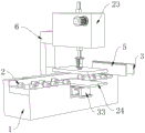
FIG. 1 is a schematic structural view of the present invention as a whole;
FIG. 2 is a side view of the present invention in its entirety;
FIG. 3 is a partial cross-sectional view of the invention as a whole;
FIG. 4 is a partial schematic structural view of a reciprocating punch forming structure according to the present invention;
FIG. 5 is a schematic view of a part of the reciprocating processing driving structure of the present invention;
FIG. 6 is a partial schematic structural view of a force component compression protection support structure according to the present invention;
fig. 7 is a partial cross-sectional view of a force component compression protection support structure of the present invention.
In the figure: 1. processing a lapping table; 2. a feeding auxiliary wheel; 3. positioning a plate; 4. a hydraulic push rod cylinder; 5. a feeding push plate; 6. a support arm; 7. placing the containing box; 8. a guide limiting block; 9. a stepping motor; 10. a drive output gear; 11. a driven driving gear; 12. a limit matching gear; 13. a regulating gear is matched; 14. a follow motion block; 15. a limiting carrying groove block; 16. deducing a material pressing rod; 17. reciprocating to process the driving structure; 18. connecting a gasket; 19. a stressed housing; 20. a first damping spring; 21. pushing the guide rod in a counterforce; 22. stamping a material plate; 23. a reciprocating punch forming structure; 24. processing a top plate in a matching way; 25. the bottom plate is locked; 26. carrying a support frame; 27. the component force is matched with the guide post; 28. a movable guide rod; 29. an auxiliary stress plate; 30. a stressed main rod; 31. a second damping spring; 32. a third damping spring; 33. the component force is pressed to protect the support structure.
Detailed Description
In order to make the objects, technical solutions and advantages of the present invention more clearly apparent, the present invention is further described in detail below with reference to the accompanying drawings and embodiments. It should be understood that the specific embodiments described herein are merely illustrative of the present invention and are not intended to limit the present invention.
Referring to fig. 1-7, the reciprocating rapid production and processing device for the square plate comprises a processing and erecting platform 1, wherein a plurality of feeding auxiliary wheels 2 are fixed at the top end of the processing and erecting platform 1, a positioning plate 3 is welded at one end of the upper surface of the processing and erecting platform 1, a hydraulic push rod cylinder 4 is fixed at one end of the positioning plate 3 through a screw, a feeding push plate 5 is fixed at the output end of the hydraulic push rod cylinder 4, supporting arms 6 are welded at two sides of the processing and erecting platform 1, and a reciprocating punch forming structure 23 is welded at one side of each supporting arm 6;
the reciprocating punch forming structure 23 comprises a containing box 7, a guide limiting block 8, a reciprocating machining driving structure 17, a connecting gasket 18, a stressed shell 19, a first damping spring 20 and a reaction push guide rod 21, the reciprocating machining driving structure 17 is assembled inside the containing box 7, the connecting gasket 18 is fixed at the bottom end of the reciprocating machining driving structure 17, the stressed shell 19 is welded at the bottom end of the connecting gasket 18, the first damping spring 20 and the reaction push guide rod 21 are installed inside the stressed shell 19, the reaction push guide rod 21 is in clearance fit with the stressed shell 19, the reaction push guide rod 21 is located at the bottom end of the first damping spring 20, and a punching plate 22 is welded at the bottom end of the reaction push guide rod 21;
the reciprocating processing driving structure 17 comprises a stepping motor 9, a driving output gear 10, a driven driving gear 11, a limit matching gear 12, a matching adjusting gear 13, a following motion block 14, a limit carrying groove block 15 and a derivation material pressing rod 16, wherein the output end of the stepping motor 9 is rotatably connected with the driving output gear 10, one side of the driving output gear 10 is meshed and connected with the driven driving gear 11, one end of the driven driving gear 11 is connected with the limit matching gear 12 through a roller bearing, one end of the outer surface of the driven driving gear 11 is welded with a rotating shaft, the matching adjusting gear 13 is sleeved on the outer side of the rotating shaft, the matching adjusting gear 13 is meshed and connected with the limit matching gear 12, one end of the matching adjusting gear 13 is rotatably connected with the following motion block 14, the following motion block 14 is slidably connected with the limit carrying groove block 15, and the derivation material pressing rods 16 are welded at the top end and the bottom end, the derivation material pressing rod 16 and the guide limiting block 8 are in clearance fit.
The scheme has the following working processes:
the output end of the hydraulic push rod cylinder 4 extends to push the feeding push plate 5, so that the feeding push plate 5 pushes the material plate, the stable discharging pushing is formed by matching the rolling of the feeding auxiliary wheel 2, one end of the material plate is positioned at the bottom end of the reciprocating punch forming structure 23 and the top end of the matching processing top plate 24, at the moment, the stepping motor 9 is started to rotate to drive the driving output gear 10 to rotate, the driven driving gear 11 is driven to synchronously rotate in a matching way, because the roller bearing between the driven driving gear 11 and the spacing matching gear 12 is a roller bearing with an inward-turning and outward-turning structure, the rotation of the driven driving gear 11 cannot influence the spacing matching gear 12, the spacing matching gear 12 does not rotate, at the moment, because the driven driving gear 11 is connected with the matching adjusting gear 13, the driven driving gear 11 can drive the matching adjusting gear 13 to rotate, the matching adjusting gear 13 is matched to drive the following moving block 14 to move, when the matching adjusting gear 13 is driven to one side of the limiting matching gear 12, the following moving block 14 slides to one end of the limiting carrying groove block 15, the derivation material pressing rod 16 is driven to form the same extending distance between the top end and the bottom end, when the matching adjusting gear 13 is driven to the highest point of the driven driving gear 11, the following moving block 14 slides to the middle position of the limiting carrying groove block 15, the derivation material pressing rod 16 slides upwards under the guidance of the guiding limiting block 8 to finish contraction, when the matching adjusting gear 13 is driven to the lowest point of the driven driving gear 11, the following moving block 14 is still located at the middle position of the limiting carrying groove block 15, and the derivation material pressing rod 16 forms downward punching under the guidance of the guiding limiting block 8 through limiting;
in the process of punching by the reciprocating processing driving structure 17 to drive the punching material plate 22, because the punching material plate 22 is subjected to the conduction of the counter-force to the top when being punched to the material plate, the punching material plate 22 drives the counter-force push guide rod 21 to extrude to the position of the stressed shell 19 to a certain extent, so that the stressed shell 19 is compressed to form pressure potential energy, the pressure potential energy is used as counteracting force, and the continuous conduction of the counter-force is reduced to damage the subsequent structure;
because the flitch is at the top end of the top plate 24, when the flitch is pressed, the top plate 24 is matched with the component force pressed protection supporting structure 33 to form a support, the impact pressure is directly pressed downwards through the matching of the top plate 24 and the auxiliary stress plate 29, the component force matching guide post 27 and the stress main rod 30 are respectively welded at the four corners and the lower surface of the bottom end of the auxiliary stress plate 29, the pressure on the edge is divided through the component force matching guide post 27, the pressure is prevented from being directly and completely acted on the stress main rod 30, the divided pressure is guided into the inside of the third damping spring 32 through the third damping spring 32 by the conduction of the movable guide rod 28, the pressure conducted by the stress main rod 30 is guided into the inside of the second damping spring 31 by compressing the second damping spring 31, and the elastic deformation of the third damping spring 32 and the second damping spring 31 is utilized to offset, the supporting effect is improved, and simultaneously, the reaction force formed after the force is counteracted is reduced due to the principle of force interaction.
According to the working process, the following steps are known:
1. according to the invention, through the design of the reciprocating punch forming structure 23, the device is convenient to achieve stable lifting frequency through gear matching conduction, and the matching design is counteracted by utilizing the return force, so that the forming and punching efficiency of the forming production, the uniformity of the formed outer pipe and the good service life are ensured;
2. according to the invention, through the combined design of the component force pressed protection supporting structure 33 and the matched processing top plate 24, the device can form good stamping bearing in the use process, the damage of the bottom plate caused by excessive pressure in the stamping forming process is avoided, the forming of bottom counter force is reduced by utilizing the design advantages of the structure, and the use effect of the device is improved.
Further, a matching deep groove is formed inside the machining carrying platform 1, a component force compression protection supporting structure 33 is fixed at the top end of the matching deep groove, the component force compression protection supporting structure 33 comprises a locking bottom plate 25, a carrying support frame 26, a component force matching guide post 27, a movable guide rod 28, an auxiliary stress plate 29, a stress main rod 30, a second damping spring 31 and a third damping spring 32, the carrying support frame 26 is welded at the top end of the locking bottom plate 25, the component force matching guide posts 27 are installed inside four end corners of the carrying support frame 26, the movable guide rod 28 and the third damping spring 32 are located inside the carrying support frame 26, the movable guide rod 28 and the component force matching guide post 27 are in clearance fit, the auxiliary stress plate 29 is welded at the top end of the movable guide rod 28, the stress main rod 30 is welded at the lower surface of the auxiliary stress plate 29, and the stress main rod 30 is connected with the locking bottom plate 25 through the second damping spring 31, the top end of the component force compression protection supporting structure 33 is welded with a matched processing top plate 24;
furthermore, one end of the stepping motor 9 is completely attached to one end of the placing and accommodating box 7, and the stepping motor 9 is fixedly connected with the placing and accommodating box 7 through screws, so that the stepping motor 9 can be conveniently positioned and installed;
furthermore, matching limiting through holes are formed in the top end and the bottom end of the accommodating box 7 and the inside of the guide limiting block 8, the derivation material pressing rod 16 is in clearance fit with the matching limiting through holes, the bottom end of the reciprocating processing driving structure 17 is completely attached to the top end of the connecting gasket 18, and the reciprocating processing driving structure 17 is connected with the connecting gasket 18 through welding, so that the derivation transmission of lifting reciprocation is formed conveniently;
furthermore, square matching sliding grooves are formed in the top end and the bottom end of the derivation material pressing rod 16, and the square matching sliding grooves are in clearance fit with the limiting carrying groove blocks 15, so that the reciprocating derivation limiting is formed through the limiting conduction of the limiting carrying groove blocks 15;
further, a plane bearing is installed inside the matching adjusting gear 13, a matching rotating shaft is welded at one end of the following moving block 14, and the matching adjusting gear 13, the matching rotating shaft and the rotating shaft are connected through the plane bearing, so that the matching adjusting gear 13 can rotate around the limiting matching gear 12 under the driving of the driven driving gear 11, and driving displacement is formed;
furthermore, a guide connecting through hole is formed in the top end of the carrying support frame 26, and the guide connecting through hole is in clearance fit with the stress main rod 30, so that sliding conduction during stress is facilitated, and the direct action of stress on the carrying support frame 26 is avoided;
further, the lower surface of the component force compression protection supporting structure 33 is completely attached to the inner upper surface of the matched placing deep groove, and the component force compression protection supporting structure 33 is fixedly connected with the matched placing deep groove through screws, so that positioning support is convenient to form, and stress displacement is avoided.
The foregoing shows and describes the general principles of the present patent, its essential features, and its advantages. It will be understood by those skilled in the art that the present invention is not limited to the embodiments described above, which are only for the purpose of illustrating the principles of the present invention, but that various changes and modifications may be made therein without departing from the spirit and scope of the present invention as defined by the appended claims. The scope of the invention patent claims is defined by the appended claims and their equivalents.
Claims (9)
1. A reciprocating rapid production and processing device for square plates comprises a processing and erecting platform (1), and is characterized in that a plurality of feeding auxiliary wheels (2) are fixed at the top end of the processing and erecting platform (1), a positioning plate (3) is welded at one end of the upper surface of the processing and erecting platform (1), a hydraulic push rod cylinder (4) is fixed at one end of the positioning plate (3) through screws, a feeding push plate (5) is fixed at the output end of the hydraulic push rod cylinder (4), supporting arms (6) are welded at two sides of the processing and erecting platform (1), and a reciprocating punch forming structure (23) is welded at one side of each supporting arm (6);
the reciprocating punch forming structure (23) comprises a containing box (7), a guide limiting block (8), a reciprocating processing driving structure (17), a connecting gasket (18), a stressed shell (19), a first damping spring (20) and a counter force derivation rod (21), the inside of the placing and containing box (7) is provided with a reciprocating processing driving structure (17), a connecting gasket (18) is fixed at the bottom end of the reciprocating processing driving structure (17), a stressed shell (19) is welded at the bottom end of the connecting gasket (18), a first damping spring (20) and a counter force derivation rod (21) are arranged in the stressed shell (19), the reaction push guide rod (21) is in clearance fit with the stressed shell (19), and the reaction push guide rod (21) is positioned at the bottom end of the first damping spring (20), the bottom end of the reaction push-guide rod (21) is welded with a stamping plate (22);
the reciprocating machining driving structure (17) comprises a stepping motor (9), a driving output gear (10), a driven driving gear (11), a limiting matching gear (12), a matching adjusting gear (13), a following motion block (14), a limiting carrying groove block (15) and a derivation material pressing rod (16), wherein the output end of the stepping motor (9) is rotatably connected with the driving output gear (10), one side of the driving output gear (10) is meshed with the driven driving gear (11), one end of the driven driving gear (11) is connected with the limiting matching gear (12) through a roller bearing, one end of the outer surface of the driven driving gear (11) is welded with a rotating shaft, the matching adjusting gear (13) is sleeved on the outer side of the rotating shaft, the matching adjusting gear (13) is meshed with the limiting matching gear (12) and connected, one end of the matching adjusting gear (13) is rotatably connected with the following motion block (14), follow motion piece (14) and spacing groove piece (15) sliding connection of carrying, the top and the bottom of spacing groove piece (15) all weld and derive and press material pole (16), it presses material pole (16) and direction stopper (8) to derive for clearance fit.
2. The reciprocating rapid production and processing device for the square plate as claimed in claim 1, wherein a matching deep groove is formed inside the processing and stacking platform (1), a force component compression protection support structure (33) is fixed at the top end of the matching deep groove, the force component compression protection support structure (33) comprises a locking bottom plate (25), a carrying support frame (26), a force component matching guide pillar (27), a movable guide rod (28), an auxiliary stress plate (29), a stress main rod (30), a second damping spring (31) and a third damping spring (32), the carrying support frame (26) is welded at the top end of the locking bottom plate (25), the force component matching guide pillars (27) are installed inside four end corners of the carrying support frame (26), the movable guide rod (28) and the third damping spring (32) are both located inside the carrying support frame (26), the movable guide rod (28) is in clearance fit with the component force fit guide pillar (27), an auxiliary stress plate (29) is welded at the top end of the movable guide rod (28), a stress main rod (30) is welded on the lower surface of the auxiliary stress plate (29), the stress main rod (30) is connected with the locking bottom plate (25) through a second damping spring (31), and a matching processing top plate (24) is welded at the top end of the component force compression protection supporting structure (33).
3. The reciprocating rapid production and processing device for the square plates as claimed in claim 1, wherein one end of the stepping motor (9) is completely attached to one end of the accommodating box (7), and the stepping motor (9) is fixedly connected with the accommodating box (7) through screws.
4. The reciprocating rapid production and processing device for the square plates as claimed in claim 1, wherein the top end and the bottom end of the accommodating box (7) and the inside of the guide limiting block (8) are both provided with a matching limiting through hole, and the derivation pressing rod (16) is in clearance fit with the matching limiting through hole.
5. The reciprocating rapid production and processing device for the square plates as claimed in claim 1, wherein square fit sliding grooves are formed at the top end and the bottom end of the material pushing and pressing rod (16), and the square fit sliding grooves are in clearance fit with the limit carrying groove blocks (15).
6. The reciprocating rapid production and processing device for the square plates as claimed in claim 1, wherein a plane bearing is installed inside the matching adjusting gear (13), a matching rotating shaft is welded at one end of the following moving block (14), and the matching adjusting gear (13), the matching rotating shaft and the rotating shaft are connected through the plane bearing.
7. The reciprocating rapid production and processing device for the square plates as claimed in claim 2, wherein a guide connecting through hole is formed inside the top end of the carrying support frame (26), and the guide connecting through hole is in clearance fit with the stress main rod (30).
8. The reciprocating rapid production and processing device for the square plate as claimed in claim 1, wherein the lower surface of the force component pressure protection supporting structure (33) is completely attached to the inner upper surface of the matched deep groove, and the force component pressure protection supporting structure (33) is fixedly connected with the matched deep groove through a screw.
9. The reciprocating rapid production and processing device for the square plate as claimed in claim 1, wherein the bottom end of the reciprocating processing driving structure (17) is completely attached to the top end of the connecting gasket (18), and the reciprocating processing driving structure (17) is connected with the connecting gasket (18) by welding.
Priority Applications (1)
| Application Number | Priority Date | Filing Date | Title |
|---|---|---|---|
| CN202010690050.2A CN111889555A (en) | 2020-07-17 | 2020-07-17 | Reciprocal quick production processingequipment of square board |
Applications Claiming Priority (1)
| Application Number | Priority Date | Filing Date | Title |
|---|---|---|---|
| CN202010690050.2A CN111889555A (en) | 2020-07-17 | 2020-07-17 | Reciprocal quick production processingequipment of square board |
Publications (1)
| Publication Number | Publication Date |
|---|---|
| CN111889555A true CN111889555A (en) | 2020-11-06 |
Family
ID=73189404
Family Applications (1)
| Application Number | Title | Priority Date | Filing Date |
|---|---|---|---|
| CN202010690050.2A Withdrawn CN111889555A (en) | 2020-07-17 | 2020-07-17 | Reciprocal quick production processingequipment of square board |
Country Status (1)
| Country | Link |
|---|---|
| CN (1) | CN111889555A (en) |
Cited By (1)
| Publication number | Priority date | Publication date | Assignee | Title |
|---|---|---|---|---|
| CN113019661A (en) * | 2021-04-09 | 2021-06-25 | 马鞍山市炆烨机械制造有限公司 | Waste crushing device for machine manufacturing and using method thereof |
Citations (7)
| Publication number | Priority date | Publication date | Assignee | Title |
|---|---|---|---|---|
| WO2008126590A1 (en) * | 2007-03-14 | 2008-10-23 | Ihi Corporation | Press machine |
| CN203068979U (en) * | 2012-12-04 | 2013-07-17 | 安徽省宁国市宁武耐磨材料厂 | Push type feed structure of resistance furnace |
| CN108097790A (en) * | 2018-01-30 | 2018-06-01 | 重庆市长寿区维凤商贸有限公司 | A kind of circle accessory decompressor |
| CN108620476A (en) * | 2018-06-06 | 2018-10-09 | 湖州坚美电声元件有限公司 | A kind of safe hole punched device of stamping parts |
| CN208944917U (en) * | 2018-09-11 | 2019-06-07 | 保定市沧龙不锈钢精密铸造有限公司 | A kind of five metalworking stamping devices |
| CN110644488A (en) * | 2019-09-26 | 2020-01-03 | 侯德萌 | Transmission ratio adjustable equidistance pile driver |
| CN210788969U (en) * | 2019-11-04 | 2020-06-19 | 常州盛悦金属新材料有限公司 | Feeding assembly for extension device |
-
2020
- 2020-07-17 CN CN202010690050.2A patent/CN111889555A/en not_active Withdrawn
Patent Citations (7)
| Publication number | Priority date | Publication date | Assignee | Title |
|---|---|---|---|---|
| WO2008126590A1 (en) * | 2007-03-14 | 2008-10-23 | Ihi Corporation | Press machine |
| CN203068979U (en) * | 2012-12-04 | 2013-07-17 | 安徽省宁国市宁武耐磨材料厂 | Push type feed structure of resistance furnace |
| CN108097790A (en) * | 2018-01-30 | 2018-06-01 | 重庆市长寿区维凤商贸有限公司 | A kind of circle accessory decompressor |
| CN108620476A (en) * | 2018-06-06 | 2018-10-09 | 湖州坚美电声元件有限公司 | A kind of safe hole punched device of stamping parts |
| CN208944917U (en) * | 2018-09-11 | 2019-06-07 | 保定市沧龙不锈钢精密铸造有限公司 | A kind of five metalworking stamping devices |
| CN110644488A (en) * | 2019-09-26 | 2020-01-03 | 侯德萌 | Transmission ratio adjustable equidistance pile driver |
| CN210788969U (en) * | 2019-11-04 | 2020-06-19 | 常州盛悦金属新材料有限公司 | Feeding assembly for extension device |
Cited By (1)
| Publication number | Priority date | Publication date | Assignee | Title |
|---|---|---|---|---|
| CN113019661A (en) * | 2021-04-09 | 2021-06-25 | 马鞍山市炆烨机械制造有限公司 | Waste crushing device for machine manufacturing and using method thereof |
Similar Documents
| Publication | Publication Date | Title |
|---|---|---|
| CN215239825U (en) | A grinding device for gear deburring | |
| CN214442220U (en) | Titanium alloy nut stamping device | |
| CN219052574U (en) | Punching machine capable of automatically ejecting stamping parts | |
| CN210997369U (en) | Bearing press-in device for machining | |
| CN210523501U (en) | Punch press is used in metal product processing | |
| CN211539113U (en) | Buffer device for punch press | |
| CN209288100U (en) | A kind of stamping die slid convenient for punching press bits | |
| CN214644253U (en) | Punching structure for storage battery shell | |
| CN213793710U (en) | Punching equipment is used in aluminum alloy ex-trusions production | |
| CN214976954U (en) | A punching machine for producing relay | |
| CN217595647U (en) | Stamping plate stamping device convenient to change mould | |
| CN216461263U (en) | Single-sequence punch die | |
| CN213496293U (en) | Full-automatic spin riveting press riveter | |
| CN117696717A (en) | Stamping forming device and method for stainless steel locking gasket for nuclear power | |
| CN212704010U (en) | Stamping die for sheet metal shell of electric device | |
| CN221388284U (en) | Stamping die for sheet metal part wrap angle | |
| CN210817153U (en) | Cable forming device | |
| CN222094398U (en) | A sheet metal stamping part bending forming mechanism | |
| CN113477793A (en) | Punching mechanism for processing battery steel shell metal plate | |
| CN220444778U (en) | A kind of transformer shell stamping machine | |
| CN205096309U (en) | Stabilize formula punching machine | |
| CN219335530U (en) | Stamping jig structure | |
| CN224208891U (en) | Stamping deformation device for automobile sheet metal parts | |
| CN222220833U (en) | Stamping device | |
| CN219616467U (en) | Punch press convenient to fixed work piece |
Legal Events
| Date | Code | Title | Description |
|---|---|---|---|
| PB01 | Publication | ||
| PB01 | Publication | ||
| SE01 | Entry into force of request for substantive examination | ||
| SE01 | Entry into force of request for substantive examination | ||
| WW01 | Invention patent application withdrawn after publication | ||
| WW01 | Invention patent application withdrawn after publication |
Application publication date: 20201106 |