CN111887273B - Medium-sized stretched noodle filament cutter for noodle shop - Google Patents
Medium-sized stretched noodle filament cutter for noodle shop Download PDFInfo
- Publication number
- CN111887273B CN111887273B CN202010742879.2A CN202010742879A CN111887273B CN 111887273 B CN111887273 B CN 111887273B CN 202010742879 A CN202010742879 A CN 202010742879A CN 111887273 B CN111887273 B CN 111887273B
- Authority
- CN
- China
- Prior art keywords
- bottom plate
- noodle
- motor
- rotating
- worm
- Prior art date
- Legal status (The legal status is an assumption and is not a legal conclusion. Google has not performed a legal analysis and makes no representation as to the accuracy of the status listed.)
- Active
Links
Images


Classifications
-
- A—HUMAN NECESSITIES
- A21—BAKING; EDIBLE DOUGHS
- A21C—MACHINES OR EQUIPMENT FOR MAKING OR PROCESSING DOUGHS; HANDLING BAKED ARTICLES MADE FROM DOUGH
- A21C11/00—Other machines for forming the dough into its final shape before cooking or baking
- A21C11/10—Other machines for forming the dough into its final shape before cooking or baking combined with cutting apparatus
Abstract
The invention relates to a filament cutter, in particular to a medium-sized stretched noodle filament cutter for a noodle shop. The technical problem to be solved is to provide a medium-sized stretched noodle filament cutter for a noodle house, which can realize the transmission of noodle skins and the cutting and collection of the noodle skins. The technical scheme of the invention is as follows: a medium-sized stretched noodle filament cutter for noodle houses comprises a bottom plate and a motor, wherein the motor is arranged on one side of the bottom plate; the middle of the bottom plate is connected with the workbench; the dough sheet conveying mechanism is connected between the workbench and the bottom plate, and parts of the dough sheet conveying mechanism are connected with the motor; a dough cutting mechanism is connected between the bottom plate and the dough sheet feeding mechanism. Through the cooperation between motor, send face skin mechanism and the tangent plane mechanism, can realize constantly conveying the face skin and shredding the effect to the face skin, need not the staff with its constantly cutting, labour saving and time saving improves work efficiency.
Description
Technical Field
The invention relates to a filament cutter, in particular to a medium-sized stretched noodle filament cutter for a noodle shop.
Background
The hand-pulled noodles are also called as throwing, pulling and stretching noodles, and are traditional cooked wheaten foods with unique local flavor in cities and countryside in northern China, and are popular among people and have been named after stretched noodles in Shandong Fushan mountain. The technical performance of making the stretched noodles is very strong, and the correct key must be mastered to make the stretched noodles, namely, the kneaded noodles must be prevented from being dehydrated, the shaking strips must be uniform, the strips are uniformly rolled, the noodles are put into a pot and spread, and the lumps and lumps in a pan are prevented, so that the stretched noodles are cut into shreds very important.
The patent application CN201820100771.1 discloses a novel stretched noodle cutting device, which comprises a support and at least two racks, wherein the racks are movably arranged on the support, and the novel stretched noodle cutting device is characterized by further comprising a rotating shaft, a pull wire, a wire wheel arranged on the rotating shaft and a spring; the rotating shaft is provided with a gear matched with the racks, one end of the stay wire is wound on the wire wheel, and the other end of the stay wire is fixed on the spring by bypassing the end parts of the two racks on the same side. This equipment can replace the cutter to cut the noodle, can avoid dragging the dough ball that the adhesion produced when drawing the face absolutely with the hand, but needs people to promote the face skin, can grow certain manpower like this.
In order to improve the prior art, a medium-sized stretched noodle filament cutter for a noodle house, which can realize the dough delivery and the dough cutting and collecting, is developed.
Disclosure of Invention
In order to overcome the cutting face skin of the existing equipment, need manual conveying face skin, the shortcoming that wastes time and energy, the technical problem that solves is: provides a medium-sized stretched noodle filament cutter for noodle houses, which can realize the transmission of noodle wrappers and the cutting and collection of the noodle wrappers.
The technical scheme of the invention is as follows: a medium-sized stretched noodle filament cutter for noodle houses comprises:
the motor is arranged on one side of the bottom plate;
the middle of the bottom plate is connected with the workbench;
the dough sheet conveying mechanism is connected between the workbench and the bottom plate, and parts of the dough sheet conveying mechanism are connected with the motor;
a dough cutting mechanism is connected between the bottom plate and the dough sheet feeding mechanism.
As a preferred technical scheme of the invention, the dough delivering mechanism comprises:
the side of the bottom plate, which is close to the motor, is rotatably connected with a worm, and the side part of the worm is connected with a tangent plane mechanism;
the first transmission device is connected between the worm and the output shaft of the motor;
the worm wheel is rotatably connected on one side of the bottom plate, which is close to the worm, and the worm wheel is meshed with the worm;
the bottom plate is rotatably connected with a rotating shaft close to one side of the worm wheel, and a first bevel gear set is connected between the rotating shaft and the worm wheel;
the front part of the left side of the bottom plate is rotatably connected with a rotating shaft which is positioned at the side part of the motor;
the second conveying device is connected between the rotating shaft and the left side of the rotating shaft;
the end part of the rotating shaft is connected with the trombone connecting rod;
the tail end of the long connecting rod is rotatably connected with the short connecting rod;
the driving plate is connected with the driving plate used for placing dough sheets in a sliding mode at the top of the workbench, and the driving plate is connected with the short connecting rod in a rotating mode.
As a preferred technical scheme of the invention, the section cutting mechanism comprises:
the right side of the bottom plate is rotatably connected with a first transmission shaft;
the second bevel gear set is connected between the first transmission shaft and the worm;
the rear part of the right side of the bottom plate is connected with the fixed vertical rod;
the third conveying device is connected between the first rotating pin and the rear end of the first transmission shaft;
the chain device is connected between the second rotating pin and the first rotating pin;
the second rotating pin is connected with the circular rotating disc;
the eccentric position of the front side of the circular rotating disc is rotatably connected with the matching connecting rod;
the fixed upright stanchion is connected with a square sliding sleeve in a sliding way, and the bottom of the square sliding sleeve is connected with a matching connecting rod in a rotating way;
the rear part of the left side of the bottom plate is connected with a guide post;
the cutter, square sliding sleeve rear end is connected with the cutter that is used for cutting the face skin, and the cutter is connected with the guide post slidingtype.
As a preferred technical scheme of the invention, the device also comprises a surface blocking mechanism, and the surface blocking mechanism comprises:
the side of the bottom plate, which is far away from the first transmission shaft, is rotatably connected with the third transmission shaft;
a third bevel gear set is connected between the third bevel gear set and the third bevel gear set;
the rear part of the left side of the bottom plate is rotatably connected with a gear lack which is positioned on the side part of the guide post;
the fourth conveying device is connected between the front end of the missing gear and the third-letter transmission shaft;
the rear part of the right side of the bottom plate is connected with a slotted long rod;
the baffle plate is connected with the slotted long rod in a sliding mode, a rack is arranged on the left side of the baffle plate, and the rack is meshed with the gear lacking.
As a preferred embodiment of the present invention, the present invention further comprises:
a collecting box for collecting the stretched noodles is arranged at the rear side of the bottom plate.
Compared with the prior art, the invention has the following advantages: 1. through the cooperation between motor, send face skin mechanism and the tangent plane mechanism, can realize constantly conveying the face skin and shredding the effect to the face skin, need not the staff with its constantly cutting, labour saving and time saving improves work efficiency.
2. Through keeping off the cooperation between face mechanism and the collection box, can realize receiving the stretched noodles that cut and scrape and collect.
Drawings
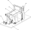
Fig. 1 is a schematic perspective view of the present invention.
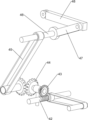
FIG. 2 is a schematic structural view of a dough delivery mechanism of the present invention.
FIG. 3 is a schematic view of a part of the structure of the dough delivery mechanism of the present invention.
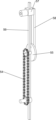
Fig. 4 is a schematic structural diagram of a section cutting mechanism of the present invention.
FIG. 5 is a schematic view of a section mechanism of the present invention.
Fig. 6 is a schematic structural diagram of the surface blocking mechanism of the present invention.
Wherein: 1. the device comprises a base plate, 2, a motor, 3, a workbench, 4, a dough sheet conveying mechanism, 41, a first conveying device, 42, a worm, 43, a worm wheel, 44, a first bevel gear set, 45, a second conveying device, 46, a rotating shaft, 47, a trombone connecting rod, 48, a trombone connecting rod, 49, a driving plate, 5, a tangent plane mechanism, 51, a second bevel gear set, 52, a transmission shaft A, 53, a third conveying device, 54, a chain device, 55, a circular rotating disc, 56, a fixed vertical rod, 57, a square sliding sleeve, 58, a matching connecting rod, 59, a cutter, 510, a guide column, 6, a face blocking mechanism, 61, a third bevel gear set, 62, a transmission shaft C, 63, a fourth conveying device, 64, a missing gear, 65, a baffle, 66, a slotted long rod, 7 and a collecting box.
Detailed Description
It is to be noted that, in the case of the different described embodiments, identical components are provided with the same reference numerals or the same component names, wherein the disclosure contained in the entire description can be transferred to identical components having the same reference numerals or the same component names in a meaningful manner. The positional references selected in the description, such as upper, lower, lateral, etc., refer also to the directly described and illustrated figures and are to be read into the new position in the sense of a change in position.
Example 1
A middle-sized stretched noodle filament cutter for a noodle shop is shown in figure 1 and comprises a bottom plate 1, a motor 2, a workbench 3, a noodle delivering mechanism 4 and a noodle cutting mechanism 5, wherein the motor 2 is arranged on the left part of the front side of the bottom plate 1, the workbench 3 is connected in the middle of the bottom plate 1, the noodle delivering mechanism 4 is connected between the workbench 3 and the bottom plate 1, the part of the noodle delivering mechanism 4 is connected with the motor 2, and the noodle cutting mechanism 5 is connected between the bottom plate 1 and the noodle delivering mechanism 4.
When people need shred the stretched noodles, place the dough sheet on sending the part of dough sheet mechanism 4 earlier, motor 2 is restarted, motor 2 output shaft rotates and drives and send dough sheet mechanism 4 to rotate, and then drive dough sheet back-and-forth movement, when the dough sheet moves backward to the part below of tangent plane mechanism 5, motor 2 output shaft rotates and drives tangent plane mechanism 5 and constantly cuts the dough sheet, after the cutting, people take out the stretched noodles, send the part of dough sheet mechanism 4 to move forward, place new dough sheet on sending the part of dough sheet mechanism 4 again, when need not use this device, it can to close motor 2.
Example 2
On the basis of embodiment 1, as shown in fig. 2-6, the dough sheet delivering mechanism 4 comprises a first conveying device 41, a worm 42, a worm wheel 43, a first bevel gear set 44, a second conveying device 45, a rotating shaft 46, a long connecting rod 47, a short connecting rod 48 and a driving plate 49, the worm 42 is rotatably connected to the right part of the front side of the bottom plate 1, the right side of the worm 42 is connected with the dough cutting mechanism 5, the first conveying device 41 is connected between the middle side of the worm 42 and the output shaft of the motor 2, the worm wheel 43 is rotatably connected to the middle part of the front side of the bottom plate 1, the worm wheel 43 is meshed with the worm 42, the rotating shaft is rotatably connected to the left part of the front side of the bottom plate 1, the first bevel gear set 44 is connected between the right end of the rotating shaft and the rear end of the worm wheel 43, the rotating shaft 46 is rotatably connected to the front part of the left side of the bottom plate 1, the rotating shaft 46 is located at the rear side of the motor 2, the second conveying device 45 is connected between the rotating shaft 46 and the left side of the rotating shaft, the right end of the rotating shaft 46 is connected with a trombone connecting rod 47, the right side of the trombone connecting rod 47 is rotatably connected with a trombone connecting rod 48, the top of the workbench 3 is slidably connected with a driving plate 49, and the front side of the driving plate 49 is rotatably connected with the trombone connecting rod 48.
When people need to shred the stretched noodles, the stretched noodles are firstly placed on the driving plate 49, then the motor 2 is started, the output shaft of the motor 2 rotates to drive the first transmission device 41, the worm 42, the worm wheel 43, the first bevel gear set 44, the rotating shaft, the second transmission device 45 and the rotating shaft 46 to rotate, the rotating shaft 46 rotates to drive the long connecting rod 47 and the short connecting rod 48 to continuously rotate, and further drive the driving plate 49 to move back and forth, when the driving plate 49 and the stretched noodles move backwards, the cut noodles are cut by the noodle cutting mechanism 5, after the cutting is finished, people take out the stretched noodles, when the driving plate 49 moves forwards, the next stretched noodles are placed on the driving plate 49, the operation is repeated, the noodle conveying action can be finished, and when the device is not needed, the motor 2 is closed.
The section cutting mechanism 5 comprises a second bevel gear set 51, a first transmission shaft 52, a third transmission device 53, a chain device 54, a circular rotating disc 55, a fixed upright rod 56, a square sliding sleeve 57, a matching connecting rod 58, a cutter 59 and a guide column 510, the front part of the right side of the bottom plate 1 is rotatably connected with the first transmission shaft 52, the second bevel gear set 51 is connected between the front end of the first transmission shaft 52 and the right end of the worm 42, the rear part of the right side of the bottom plate 1 is connected with the fixed upright rod 56, the lower side of the fixed upright rod 56 is rotatably connected with a first rotating pin, the middle part of the fixed upright rod 56 is rotatably connected with a second rotating pin, the third transmission device 53 is connected between the rear side of the first rotating pin and the rear end of the first transmission shaft 52, the chain device 54 is connected between the second rotating pin and the first rotating pin, the front part of the second rotating pin is connected with the circular rotating disc 55, the eccentric position of the front side of the circular rotating disc 55 is rotatably connected with the matching connecting rod 58, the upside of fixed pole setting 56 is sliding type to be connected with square sliding sleeve 57, and square sliding sleeve 57 bottom is connected with supporting connecting rod 58 rotary type, and bottom plate 1 left side rear portion is connected with guide post 510, and square sliding sleeve 57 rear end is connected with cutter 59, cutter 59 and guide post 510 sliding type connection.
When the dough sheet is conveyed, the output shaft of the motor 2 rotates to drive the second bevel gear set 51, the first transmission shaft 52, the third transmission device 53, the first rotating pin, the chain device 54, the second rotating pin and the circular rotating disc 55 to rotate continuously, the matching connecting rod 58 is driven to swing continuously, the square sliding sleeve 57 and the cutter 59 are driven to move up and down continuously, the cutter 59 is enabled to cut the dough sheet into threads continuously under the cooperation of the driving plate 49, and the threads cutting of the stretched dough sheet can be finished by repeating the operations.
Example 3
On the basis of embodiment 2, as shown in fig. 6, the present invention further includes a face blocking mechanism 6, the face blocking mechanism 6 includes a third bevel gear set 61, a third transmission shaft 62, a fourth transmission device 63, a missing gear 64, a baffle 65 and a slotted long rod 66, the third transmission shaft 62 is rotatably connected in the middle of the left side of the bottom plate 1, the third bevel gear set 61 is connected between the front end of the third transmission shaft 62 and the left end of the rotating shaft 46, the missing gear 64 is rotatably connected to the rear portion of the left side of the bottom plate 1, the missing gear 64 is located at the rear side of the guide column 510, the fourth transmission device 63 is connected between the front end of the missing gear 64 and the rear side of the third transmission shaft 62, the slotted long rod 66 is connected to the rear portion of the right side of the bottom plate 1, the baffle 65 is slidably connected to the upper portion of the slotted long rod 66, and the rack is arranged on the left side of the baffle 65 and meshed with the missing gear 64.
When people need to take off the cut pulled noodles, the second conveying device 45 rotates to drive the rotating shaft 46 and the third bevel gear set 61, the third bevel gear set 61 rotates to drive the third-letter transmission shaft 62, the fourth conveying device 63 and the gear lacking wheel 64 to rotate anticlockwise, when a toothed place of the gear lacking wheel 64 is meshed with the rack, the rack and the baffle plate 65 are driven to move upwards, meanwhile, under the action of the motor 2, the driving plate 49 and the dough sheet move backwards, the dough sheet is cut into threads, when the driving plate 49 and the cut dough sheet move backwards, the toothed place of the gear lacking wheel 64 is separated from the rack, the rack and the baffle plate 65 move downwards to be in contact with the driving plate 49, the cut dough sheet is pushed out by the baffle plate 65 along with the forward movement of the driving plate 49 and the cut dough sheet, people collect the cut dough sheet, and the collection can be completed by repeating the operations.
The device also comprises a collecting box 7, and the collecting box 7 is arranged at the rear side of the bottom plate 1.
When the baffle 65 is in the process of collecting and scraping, the pulling face directly falls into the collecting box 7 so as to be convenient for people to collect.
The above description is only for the specific embodiments of the present invention, but the scope of the present invention is not limited thereto, and any person skilled in the art can easily conceive of the changes or substitutions within the technical scope of the present invention, and all the changes or substitutions should be covered within the scope of the present invention. Therefore, the protection scope of the present invention shall be subject to the protection scope of the appended claims.
Claims (1)
1. The utility model provides a medium-sized stretched noodle filament cutter is used in noodle shop which characterized in that, including: the motor-driven bicycle comprises a bottom plate (1) and a motor (2), wherein the motor (2) is arranged on one side of the bottom plate (1); the middle of the bottom plate (1) is connected with the workbench (3); the dough sheet conveying mechanism (4) is connected between the workbench (3) and the bottom plate (1), and the part of the dough sheet conveying mechanism (4) is connected with the motor (2); a dough cutting mechanism (5), wherein the dough cutting mechanism (5) is connected between the bottom plate (1) and the dough sheet conveying mechanism (4); send face skin mechanism (4) including: the worm (42) is rotatably connected to one side, close to the motor (2), of the bottom plate (1), and the side part of the worm (42) is connected with the tangent plane mechanism (5); the first transmission device (41) is connected between the worm (42) and the output shaft of the motor (2); the worm wheel (43) is rotationally connected to one side, close to the worm (42), of the bottom plate (1), and the worm wheel (43) is meshed with the worm (42); a rotating shaft is rotatably connected to one side, close to the worm wheel (43), of the bottom plate (1), and the first bevel gear set (44) is connected between the rotating shaft and the worm wheel (43); the rotating shaft (46) is rotatably connected to the front part of the left side of the bottom plate (1), and the rotating shaft (46) is positioned on the side part of the motor (2); the second conveying device (45) is connected between the rotating shaft (46) and the left side of the rotating shaft; the end part of the rotating shaft (46) is connected with the trombone connecting rod (47); the tail end of the long connecting rod (47) is rotatably connected with the short connecting rod (48); the top of the workbench (3) is connected with a driving plate (49) used for placing dough sheets in a sliding mode, and the driving plate (49) is connected with a short connecting rod (48) in a rotating mode; the noodle cutting mechanism (5) comprises: the right side of the bottom plate (1) is rotatably connected with a first transmission shaft (52); the second bevel gear set (51) is connected between the first bevel gear set (52) and the worm (42); the rear part of the right side of the bottom plate (1) is connected with a fixed vertical rod (56); the third conveying device (53), one side of the fixed vertical rod (56) close to the first transmission shaft (52) is rotatably connected with a first rotating pin, one side of the fixed vertical rod (56) far away from the first rotating pin is rotatably connected with a second rotating pin, and the third conveying device (53) is connected between the first rotating pin and the rear end of the first transmission shaft (52); a chain device (54), wherein the chain device (54) is connected between the second rotating pin and the first rotating pin; the second rotating pin is connected with the circular rotating disc (55); the eccentric position of the front side of the circular rotating disc (55) is rotatably connected with the matching connecting rod (58); the fixed upright stanchion (56) is connected with a square sliding sleeve (57) in a sliding way, and the bottom of the square sliding sleeve (57) is connected with a matching connecting rod (58) in a rotating way; the rear part of the left side of the bottom plate (1) is connected with a guide post (510); the rear end of the square sliding sleeve (57) is connected with a cutter (59) used for cutting dough sheets, and the cutter (59) is connected with the guide column (510) in a sliding manner; still including keeping off a face mechanism (6), keep off a face mechanism (6) including: the base plate (1) is rotatably connected with the third-letter transmission shaft (62) on one side far away from the first-letter transmission shaft (52); a third bevel gear set (61), wherein the third bevel gear set (61) is connected between the third bevel gear set (62) and the rotating shaft (46); the rear part of the left side of the bottom plate (1) is rotatably connected with the gear lack (64), and the gear lack (64) is positioned on the side part of the guide column (510); a fourth conveying device (63), wherein the fourth conveying device (63) is connected between the front end of the missing gear (64) and the third-letter transmission shaft (62); the rear part of the right side of the bottom plate (1) is connected with a slotted long rod (66); the baffle (65) is connected with the slotted long rod (66) in a sliding manner, a rack is arranged on the left side of the baffle (65), and the rack is meshed with the gear lacking wheel (64); also includes: a collecting box (7), wherein the collecting box (7) for collecting the stretched noodles is arranged at the rear side of the bottom plate (1).
Priority Applications (1)
| Application Number | Priority Date | Filing Date | Title |
|---|---|---|---|
| CN202010742879.2A CN111887273B (en) | 2020-07-29 | 2020-07-29 | Medium-sized stretched noodle filament cutter for noodle shop |
Applications Claiming Priority (1)
| Application Number | Priority Date | Filing Date | Title |
|---|---|---|---|
| CN202010742879.2A CN111887273B (en) | 2020-07-29 | 2020-07-29 | Medium-sized stretched noodle filament cutter for noodle shop |
Publications (2)
| Publication Number | Publication Date |
|---|---|
| CN111887273A CN111887273A (en) | 2020-11-06 |
| CN111887273B true CN111887273B (en) | 2021-11-30 |
Family
ID=73182431
Family Applications (1)
| Application Number | Title | Priority Date | Filing Date |
|---|---|---|---|
| CN202010742879.2A Active CN111887273B (en) | 2020-07-29 | 2020-07-29 | Medium-sized stretched noodle filament cutter for noodle shop |
Country Status (1)
| Country | Link |
|---|---|
| CN (1) | CN111887273B (en) |
Families Citing this family (2)
| Publication number | Priority date | Publication date | Assignee | Title |
|---|---|---|---|---|
| CN112776077B (en) * | 2020-12-24 | 2022-05-31 | 罗源县凤山镇企业服务中心 | Mulching film punching machine |
| CN113367169B (en) * | 2021-06-15 | 2023-06-13 | 山西鑫炳记食业股份有限公司 | Be used for flour cake cut flower device |
Family Cites Families (11)
| Publication number | Priority date | Publication date | Assignee | Title |
|---|---|---|---|---|
| KR100959104B1 (en) * | 2008-07-16 | 2010-05-25 | 삼성모바일디스플레이주식회사 | Flat display panel breaking apparatus |
| CN204377772U (en) * | 2014-12-15 | 2015-06-10 | 登封市惠达食品厂 | A kind of dough automatic cutting equipment of deep-fried twisted dough sticks |
| CN206760599U (en) * | 2017-05-20 | 2017-12-19 | 冯永华 | A kind of hobboing cutter automatic wheaten food cutting machine |
| CN206963831U (en) * | 2017-07-11 | 2018-02-06 | 严馨华 | A kind of noodles cut air-dried all-in-one |
| CN207744650U (en) * | 2017-11-01 | 2018-08-21 | 安徽嘉诺自动化设备有限公司 | A kind of Novel wheaten food cutting bed |
| CN109531646B (en) * | 2018-10-24 | 2021-10-26 | 威海松龄诺可佳中药饮片股份有限公司 | Ginseng section device that security is strong |
| CN109623928A (en) * | 2019-01-24 | 2019-04-16 | 刘景岳 | A kind of Tofu processing cutting device with automatic propulsion functions |
| CN209882921U (en) * | 2019-03-28 | 2020-01-03 | 廊坊市盛兴食品机械有限公司 | Full-automatic spring roll system skin machine |
| CN209812423U (en) * | 2019-04-27 | 2019-12-20 | 山东方舟生物科技有限公司 | Medicinal material cutting device for preparing traditional Chinese medicine preparation |
| CN210436195U (en) * | 2019-08-14 | 2020-05-01 | 唐山聚业机械设备制造有限公司 | Slicer for food processing |
| CN210850450U (en) * | 2019-09-29 | 2020-06-26 | 合肥国瑞橡胶制品有限公司 | Rubber tire capsule slitter |
-
2020
- 2020-07-29 CN CN202010742879.2A patent/CN111887273B/en active Active
Also Published As
| Publication number | Publication date |
|---|---|
| CN111887273A (en) | 2020-11-06 |
Similar Documents
| Publication | Publication Date | Title |
|---|---|---|
| CN111887273B (en) | Medium-sized stretched noodle filament cutter for noodle shop | |
| CN203251915U (en) | Multifunctional sugarcane machine | |
| CN111844481A (en) | Stone moving machine | |
| CN111086037B (en) | Radish pickling and dicing device and using method thereof | |
| CN111496851A (en) | Bamboo shoots shred device of dried bamboo shoots preparation usefulness | |
| CN213765967U (en) | Sugarcane cutting device | |
| CN111687918B (en) | Quick potato chip cutting machine | |
| CN111633702B (en) | Traditional chinese medicine branch of academic or vocational study medicinal material rolls equipment | |
| CN112518846A (en) | Sugarcane equidistance cutter for food processing | |
| CN111906835A (en) | Device for cutting ham into flower | |
| CN111941504B (en) | Agricultural garlic auxiliary cutting device | |
| CN209737801U (en) | Forest cutting device | |
| CN212464704U (en) | Novel face sprinkling device suitable for noodle processing | |
| CN205325804U (en) | Automatic buster of portable pineapple of double knives utensil fruit eye | |
| CN111838232A (en) | Cut-off type dough blocking device | |
| CN208854691U (en) | Cake cutting machine | |
| CN213081649U (en) | Novel automatic sugarcane chopping device | |
| CN205213434U (en) | Lotus leaf reaping apparatus | |
| CN220638313U (en) | Indoor firewood cutter | |
| CN213074247U (en) | Noodle slitting device | |
| CN218891946U (en) | Efficient dicing equipment for potato seed preparation | |
| CN220308380U (en) | Cleaning and collecting device for flammulina velutipes root fungus residues | |
| CN219323122U (en) | Dough layering cutting device | |
| CN211164104U (en) | Toilet paper production and processing is with cutting package and put | |
| CN219628723U (en) | Cutting equipment for processing minced meat |
Legal Events
| Date | Code | Title | Description |
|---|---|---|---|
| PB01 | Publication | ||
| PB01 | Publication | ||
| SE01 | Entry into force of request for substantive examination | ||
| SE01 | Entry into force of request for substantive examination | ||
| CB02 | Change of applicant information | ||
| CB02 | Change of applicant information |
Address after: 518000 Guangming District, Shenzhen City, Guangdong Province Applicant after: Wu Huimin Address before: 511300 room 1601, building 12, entrepreneurship center, Zengcheng low carbon headquarters, No. 400, Xincheng Avenue, Zengcheng District, Guangzhou, Guangdong Applicant before: Wu Huimin |
|
| CB03 | Change of inventor or designer information | ||
| CB03 | Change of inventor or designer information |
Inventor after: Yang Yanlin Inventor after: Wu Huimin Inventor before: Wu Huimin |
|
| GR01 | Patent grant | ||
| GR01 | Patent grant |