Disclosure of Invention
The invention aims to relate to a self-propelled straw returning and cultivating integrated machine, which integrates straw cleaning, rotary tillage and sowing into a whole in a small volume, cleans the straws again before sowing, and crushes the straws for multiple times before cleaning, has small vehicle load, accelerates the decomposition of the straws and does not influence the sowing and seedling emergence.
The purpose of the invention is realized by the following technical scheme:
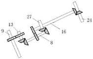
a self-propelled straw returning and farming all-in-one machine comprises a frame 26, wherein a straw smashing and cleaning machine is mounted at the front end of the frame 26, an engine 25 is mounted below the front end of the frame 26, front and rear wheels are mounted below the frame 26, a rotary cultivator is mounted on the frame between the front and rear wheels, and a seeder is mounted at the rear end of the frame 26; the output shaft 8 of the engine 25 is connected with the second transmission shaft 9 of the straw crushing and cleaning machine through a crossed shaft gear pair, the output shaft 8 is connected with the fourth transmission shaft 24 of the rotary cultivator through a crossed shaft gear pair, and the output shaft 8 is connected with the wheel driving shaft 27 through a crossed shaft gear pair.
As a more excellent technical scheme of the invention: the straw crushing and cleaning machine comprises a mounting frame 7 connected to a suspension mechanism at the front end of a frame, a cleaning mechanism, a transmission mechanism and a crushing mechanism are mounted on the mounting frame 7, and the crushing mechanism is positioned at the front end of the cleaning mechanism; the transmission mechanism comprises an engine output shaft 8, a first transmission shaft 2, a second transmission shaft 9 and a third transmission shaft 13 of a matched tractor, which are connected on the mounting frame 7 through bearings, the third transmission shaft 13 is connected with the output shaft 8 of the engine 25 through a crossed shaft gear pair, the third transmission shaft 13 is connected with the second transmission shaft through a parallel shaft gear pair, and the first transmission shaft 2 is in transmission connection with the second transmission shaft 9 through a belt; the cleaning mechanism comprises a cleaning rake rod 14, a cleaning rake 5 fixedly connected to the cleaning rake rod 14 and cleaning teeth 15 fixed to the mounting frame 7, the cleaning teeth 15 are located behind the cleaning rake 5, the cleaning rake rod 14 is connected to a cross beam of the mounting frame 7 through a bearing, and one end of the cleaning rake rod 14 is connected with the second transmission shaft 9 through a crossed shaft gear pair; the crushing mechanism include crushing wheel 4 and hammer leaf 1, the fixed connection that 4 slopes of crushing wheel is on first transmission shaft 2, hammer leaf 1 fixed connection is on the first transmission shaft 2 of 4 both sides of crushing wheel, crushing wheel 4 on fixedly connected with smash tooth 3.
As a more excellent technical scheme of the invention: the rotary cultivator comprises a rotary cultivator frame 23, a fourth transmission shaft 24, a fifth transmission shaft 17 and a sixth transmission shaft 16 are fixed on the rotary cultivator frame 23, the fourth transmission shaft 24 is in belt transmission connection with the fifth transmission shaft 17, a rotary blade 22 is fixed on the fifth transmission shaft 17, rotary blade teeth 28 are fixed on the rotary blade, the fourth transmission shaft 24 is connected with the sixth transmission shaft 16 through a crossed shaft gear pair, and the sixth transmission shaft 16 is connected with an engine output shaft 8 through a parallel shaft gear pair; the middle part of the rear end of the rotary tillage frame 23 is provided with a deep tillage plough 29, two sides of the deep tillage plough 29 are provided with fertilizer application ploughs 19, and the fertilizer application ploughs 19 are communicated with a fertilizer storage box 20 through fertilizer application pipes.
As a more excellent technical scheme of the invention: the seeder comprises a seed storage box 21 connected with the tail of the matched tractor, and the lower end of the seed storage box 21 is connected with a seeder 18.
As a more excellent technical scheme of the invention: the engine output shaft 8 is connected with a wheel driving shaft 27 through a crossed shaft gear pair.
As a more excellent technical scheme of the invention: the center of the crushing wheel piece 4 is provided with an inclined hole, the edge of the inclined hole extends out of a circular convex edge 12, the first transmission shaft 2 penetrates through the inclined hole and the circular convex edge 12, the circular convex edge 12 and the first transmission shaft 2 are provided with through holes, and the crushing wheel piece 4 and the first transmission shaft 2 penetrate through the through holes through bolts to be fixedly connected.
As a more excellent technical scheme of the invention: the end surface of the crushing wheel piece 4 is provided with more than two grooves 11 along the diameter, and the crushing teeth 3 are arranged in the grooves 11 and connected through fixing bolts 10; the acute angle between the diameter of the crushing wheel piece 4 and the axis of the first transmission shaft 2 is 15-85 degrees.
As a more excellent technical scheme of the invention: the hammer pieces 1 are arranged on two sides of the crushing wheel piece, and the edges of the hammer pieces 1 are in a sawtooth shape.
As a more excellent technical scheme of the invention: the cleaning harrow 5 is Y-shaped.
As a more excellent technical scheme of the invention: the driver's seat is mounted on a frame 26 above the engine 25.
As a more excellent technical scheme of the invention: the output shaft 8 is provided with a universal connecting shaft device 30.
As a more excellent technical scheme of the invention: the sixth transmission shaft 16 is provided with a universal coupling 30.
As a more excellent technical scheme of the invention: the mounting frame 7 of the straw crushing and cleaning machine, the rotary tillage frame 23 of the rotary cultivator and the seeder are all connected with a hydraulic lifting mechanism.
The beneficial effects are as follows:
the self-propelled straw returning and cultivating integrated machine provided by the invention realizes integration of straw cleaning, rotary tillage and sowing into a whole in a small volume, realizes fine crushing of straws, has small vehicle load, accelerates decomposition of straws and does not influence sowing and seedling emergence. The straw at the bottom of the ridge is firstly crushed by the crushing blades of the straw crushing and cleaning machine, the straw is cleaned to the adjacent ridge, the hammer blade which corresponds to the upper part of the ridge crushes the straw again, the crushing harrow is crushed for the third time under the driving of the crushing harrow rod, the uncrushed straw at the ridge is driven to the bottom of the ridge, and the uncrushed straw at the bottom of the ridge is concentrated to one position by the cleaning rod. The straw is completely crushed for three times before being cleaned, the covering width of the crushing mechanism is the same as that of the cleaning mechanism, the cleaning speed is accelerated, the burden of a cleaning vehicle is reduced, the decomposition of the straw is accelerated, and the seeding and seedling emergence are not influenced.
The invention solves the problems that the rotting of the straws after returning to the field does not thoroughly affect the next year cultivation and the like due to the phenomena of fertilizer competition with seedlings, low ground temperature, water leakage, weed cluster or straw rotting caused by insufficient rainfall and the like, and the yield of the crops is obviously increased.
The invention has simple structure, low manufacturing and working cost and large operation width, improves the soil quality to the maximum extent and meets the requirement of agricultural production development.
Detailed Description
The present invention will be described in further detail with reference to the accompanying drawings.
As shown in figures 1 and 3, the invention provides a self-propelled straw returning and cultivating integrated machine, which is characterized in that: the straw crushing and cleaning machine comprises a frame 26, wherein a straw crushing and cleaning machine is installed at the front end of the frame 26, an engine 25 is installed below the front end of the frame 26, front and rear wheels are installed below the frame 26, a rotary cultivator is installed on the frame between the front and rear wheels, and a seeder is installed at the rear end of the frame 26; the output shaft 8 of the engine 25 is connected with the second transmission shaft 9 of the straw crushing and cleaning machine through a crossed shaft gear pair, the output shaft 8 is connected with the fourth transmission shaft 24 of the rotary cultivator through a crossed shaft gear pair, and the output shaft 8 is connected with the wheel driving shaft 27 through a crossed shaft gear pair.
In some embodiments, the straw crushing and cleaning machine comprises a mounting frame 7 connected to a suspension mechanism at the front end of a frame, the mounting frame 7 is provided with a cleaning mechanism, a transmission mechanism and a crushing mechanism, and the crushing mechanism is positioned at the front end of the cleaning mechanism; the transmission mechanism comprises an engine output shaft 8, a first transmission shaft 2, a second transmission shaft 9 and a third transmission shaft 13 of a matched tractor, which are connected on the mounting frame 7 through bearings, the third transmission shaft 13 is connected with the output shaft 8 of the engine 25 through a crossed shaft gear pair, the third transmission shaft 13 is connected with the second transmission shaft through a parallel shaft gear pair, and the first transmission shaft 2 is in transmission connection with the second transmission shaft 9 through a belt; the cleaning mechanism comprises a cleaning rake rod 14, a cleaning rake 5 fixedly connected to the cleaning rake rod 14 and cleaning teeth 15 fixed to the mounting frame 7, the cleaning teeth 15 are located behind the cleaning rake 5, the cleaning rake rod 14 is connected to a cross beam of the mounting frame 7 through a bearing, and one end of the cleaning rake rod 14 is connected with the second transmission shaft 9 through a crossed shaft gear pair; the crushing mechanism include crushing wheel 4 and hammer leaf 1, the fixed connection that 4 slopes of crushing wheel is on first transmission shaft 2, hammer leaf 1 fixed connection is on the first transmission shaft 2 of 4 both sides of crushing wheel, crushing wheel 4 on fixedly connected with smash tooth 3.
In some embodiments, the rotary cultivator comprises a rotary cultivator frame 23, a fourth transmission shaft 24, a fifth transmission shaft 17 and a sixth transmission shaft 16 are fixed on the rotary cultivator frame 23, the fourth transmission shaft 24 is in belt transmission connection with the fifth transmission shaft 17, a rotary blade 22 is fixed on the fifth transmission shaft 17, rotary blade teeth 28 are fixed on the rotary blade, the fourth transmission shaft 24 is connected with the sixth transmission shaft 16 through a crossed shaft gear pair, and the sixth transmission shaft 16 is connected with an output shaft 8 of the engine through a parallel shaft gear pair; the middle part of the rear end of the rotary tillage frame 23 is provided with a deep tillage plough 29, two sides of the deep tillage plough 29 are provided with fertilizer application ploughs 19, and the fertilizer application ploughs 19 are communicated with a fertilizer storage box 20 through fertilizer application pipes.
In some embodiments, the seeder comprises a seed storage box 21 connected with the tail of the matched tractor, and the lower end of the seed storage box 21 is connected with a seeder 18.
In some embodiments, the engine output shaft 8 is coupled to the wheel drive shaft 27 via a crossed-axis gear pair.
In some embodiments, an inclined hole is formed in the center of the crushing wheel piece 4, an annular convex edge 12 extends out of the edge of the inclined hole, the first transmission shaft 2 penetrates through the inclined hole and the annular convex edge 12, through holes are formed in the annular convex edge 12 and the first transmission shaft 2, and the crushing wheel piece 4 and the first transmission shaft 2 penetrate through the through holes through bolts to be fixedly connected.
In some embodiments, the end surface of the crushing wheel sheet 4 is provided with more than two grooves 11 along the diameter, and the crushing teeth 3 are arranged in the grooves 11 and connected through fixing bolts 10; the acute angle between the diameter of the crushing wheel piece 4 and the axis of the first transmission shaft 2 is 15-85 degrees.
In some embodiments, the hammer pieces 1 are arranged on two sides of the crushing wheel piece, and the edges of the hammer pieces 1 are in a sawtooth shape.
In some embodiments, the cleaning rake 5 is Y-shaped.
In some embodiments, the driver's seat is mounted on the frame 26 above the engine 25.
In some embodiments, the output shaft 8 is provided with a universal joint coupling 30.
In some embodiments, the sixth drive shaft 16 has a universal joint adapter 30 mounted thereon.
In some embodiments, the mounting frame 7 of the straw crushing and cleaning machine, the rotary tillage frame 23 of the rotary cultivator and the seeding machine are all connected with a hydraulic lifting mechanism.
The specific working process of the invention is as follows:
as shown in figure 2, an engine output shaft 8 of the self-propelled straw returning and farming all-in-one machine of the invention rotates, a bevel gear drives a third transmission shaft 13 to rotate, the third transmission shaft 13 drives a second transmission shaft 9 to rotate through a flat gear, the second transmission shaft 9 drives cleaning rake rods 14 to rotate through a bevel gear, meanwhile, the second transmission shaft 9 drives a belt pulley on a first transmission shaft 2 to rotate through a belt 6, further, the first transmission shaft 2 rotates to drive a hammer 1 and a crushing wheel 4 to rotate, crushing teeth 3 on the crushing wheel 4 crush or turn the straws out to the range covered by the hammer 1, the saw-tooth hammer 1 crushes the straws more thoroughly, then the cleaning rake rods 14 of the cleaning mechanism rotate, the number of the cleaning rake rods 14 is 4, two adjacent cleaning rake rods 14 form one group, the rotating directions of the two cleaning rake rods in each group are the same, and the rotating directions of the two cleaning rake rods 14 are opposite, simultaneously, the straw is further smashed and moved to a position between the two ridge tables along with the rotation of the cleaning harrow rods 14, the residual straw after being processed by the cleaning harrow 5 is picked up by the cleaning teeth 15 and is cleaned to a fallow area together with the straw in the field, the absence of straw in the fallow area is ensured, or only a small amount of straw is left, and the high-quality cultivation standard is reached. The output shaft 8 of the engine 25 is connected with a tractor wheel driving shaft 27 through a bevel gear. The output shaft 8 is connected with a sixth transmission shaft 16 through a flat gear, the sixth transmission shaft 16 is connected with a fourth transmission shaft 24 through a bevel gear, and the rotary cultivator works under the driving of the output shaft 8 of the engine.
The straw smashing and cleaning machine provided by the invention realizes fine smashing, wherein the smashing wheel sheet smashes straws at the ridge bottom firstly, and cleans the straws to the ridge, the hammer sheet which is right corresponding to the upper side of the ridge crush the straws again, the cleaning harrow is driven by the cleaning harrow rod to smash for the third time, the uncrushed straws at the ridge are driven to the ridge bottom, and the cleaning rod concentrates the uncrushed straws at the ridge bottom to one place. The crushing roller 4 is located right above the ridge bottom, the hammer is located right above two adjacent ridges, two cleaning raking rods 14 are arranged above each ridge, the rotating directions of the two cleaning raking rods 14 are the same, the two cleaning raking rods are both rotated to the ridge bottom between the two adjacent ridges, one of the two cleaning raking rods 14 on each ridge is located above the center of the ridge, and the other cleaning raking rod is located above the edge of the ridge. Two cleaning rakes 5 which are arranged on the same straight line are arranged on the same circumference of each cleaning rake rod 14. The Y-shaped branch distance of two cleaning rakes 5 on adjacent cleaning rake rods 14 is very close to fit, and the two cleaning rakes 5 form a crushing cleaning rake group.
In some working processes, when two ridges or three ridges are worked, the number of the crushing wheel sheets 4 is one, the crushing wheel sheets are arranged in the middle of the first transmission shaft 2, and the hammer sheets 1 are fixedly connected to the first transmission shafts 2 on two sides of the crushing wheel sheets 4.
In some working processes, when the working is carried out for more than four ridges, the number of the crushing wheel pieces 4 is two or three, the two or three crushing wheel pieces are uniformly distributed on the first transmission shaft 2, and the hammer piece 1 is fixedly connected to the first transmission shaft 2 between every two adjacent crushing wheel pieces 4.
In some working processes, when the operation of four ridges, a clearance machine is smashed to straw be two, the belt pulley of one side of one of them first transmission shaft 2 and the belt pulley fixed connection of one side of another first transmission shaft 2 are as an organic whole, the belt pulley of one side of one of them second transmission shaft 9 and the belt pulley fixed connection of one side of another second transmission shaft 9 are as an organic whole, the side of clearance harrow support of clearance mechanism passes through link fixed connection as an organic whole.
In some working processes, when six ridges work, the straw crushing and cleaning machine provided by the utility model has three machines, and the work above six ridges can be analogized.
The invention has small damage degree to soil cultivation layers, and is an ideal soil protective tillage machine.
In the present invention, unless otherwise expressly stated or limited, the terms "mounted," "connected," "secured," and the like are to be construed broadly and can, for example, be fixedly connected, detachably connected, or integrally formed; can be mechanically connected or electrically connected; they may be directly connected or indirectly connected through intervening media, or they may be connected internally or in any other suitable relationship, unless expressly stated otherwise. The specific meanings of the above terms in the present invention can be understood according to specific situations by those of ordinary skill in the art.
In the description herein, references to the description of the term "one embodiment," "some embodiments," "an example," "a specific example," or "some examples," etc., mean that a particular feature, structure, material, or characteristic described in connection with the embodiment or example is included in at least one embodiment or example of the invention. In this specification, the schematic representations of the terms used above are not necessarily intended to refer to the same embodiment or example. Furthermore, the particular features, structures, materials, or characteristics described may be combined in any suitable manner in any one or more embodiments or examples. Furthermore, various embodiments or examples and features of different embodiments or examples described in this specification can be combined and combined by one skilled in the art without contradiction.
Although embodiments of the present invention have been shown and described above, it is understood that the above embodiments are exemplary and should not be construed as limiting the present invention, and that variations, modifications, substitutions and alterations can be made to the above embodiments by those of ordinary skill in the art within the scope of the present invention.
The above-described embodiments of the present invention should not be construed as limiting the scope of the present invention. Any other corresponding changes and modifications made according to the technical idea of the present invention should be included in the protection scope of the claims of the present invention.