Curtain paving tool structure and operation method
Technical Field
The invention relates to the technical field of curtain paving tools, in particular to a curtain paving tool structure and an operation method.
Background
The bamboo-wood composite board is manufactured by stacking and pressing 24 layers of blank materials, and all the materials are required to be placed on a production line station from raw materials in the manufacturing process. One of the blanks (bamboo curtain or spread curtain) was of size 2500 x 1300 x 3. At present, curtain paving actions in the manufacturing process of the bamboo-wood composite board are all completed manually, the manual efficiency is low, the working environment is poor, and the injury to human bodies is great.
As shown in fig. 9, bamboo curtain a adopts the rope b establishment that a plurality of equidistance parallel fixed, the bamboo curtain is the slope form when placing on the platform 3 at the raw materials, and inclination is indefinite (generally not more than 45 degrees), in the subsequent handling, need carry the bamboo curtain to the assembly line place on the platform 5, and can put right after requiring the bamboo curtain to carry to the assembly line place on the platform 5, consequently need to design one kind and spread curtain frock structure urgently for replace the manual work to spread curtain (bamboo curtain) and carry out automatic just and transport.
Based on the technical scheme, the invention designs a curtain paving tool structure and an operation method to solve the problems.
Disclosure of Invention
The invention aims to provide a curtain paving tool structure and an operation method, so as to solve the technical problems.
In order to realize the purpose, the invention provides the following technical scheme: the utility model provides a spread curtain frock structure, mainly includes truss mechanism, truss mechanism inner chamber below is installed and is ajusted the mechanism, it can control the removal in truss mechanism to ajust the mechanism, the horizontal slip table subassembly of both sides around the mechanism includes, install vertical lifting unit on the horizontal slip table subassembly, vertical lifting unit's bottom is installed and is got the subassembly, truss mechanism's inner chamber below is provided with the raw materials side by side and places the platform, seeks limit correction platform and assembly line and place the platform.
Preferably, the truss mechanism comprises gantry vertical frames arranged on the left side and the right side, two groups of channel steel tracks which are parallel to each other in the front-back direction are fixedly arranged between the tops of the gantry vertical frames on the two sides, openings of the two groups of channel steel tracks are arranged oppositely, two ends of each channel steel track are respectively provided with a sprocket bearing seat, a fixed sprocket is rotatably arranged on each sprocket bearing seat through a sprocket shaft, a driving motor for driving the sprocket shaft is arranged at the top of the gantry vertical frame on one side, and a non-closed transmission chain is arranged between the fixed sprockets on the two sides; the mechanism of ajusting includes the frame of ajusting of rectangle mechanism, horizontal slip table subassembly be provided with respectively in both sides around the frame of ajusting, the top of the frame of ajusting be provided with two pairs respectively with two sets of the pulley of channel-section steel track slip gomphosis, the left and right sides of the frame of ajusting respectively be provided with be used for with the fixed chain fixed plate in driving chain both ends.
Preferably, the horizontal sliding table assembly is a screw rod sliding table driven by a stepping motor, the vertical lifting assembly comprises a lifting mounting plate mounted on a movable slider at the front side of the horizontal sliding table assembly, a lifting cylinder is vertically mounted in the middle of the lifting mounting plate, a lifting mounting frame is mounted at a bottom telescopic end of the lifting cylinder, limiting slide bars are fixedly mounted on the left side and the right side of the top of the lifting mounting frame respectively, the upper ends of the limiting slide bars penetrate through the lifting mounting plate and are slidably mounted with the lifting mounting plate through linear bearings, and the clamping assembly is fixedly mounted at the bottom of the lifting mounting plate;
preferably, the clamping assembly comprises a support mounting plate, a sliding rail sliding block assembly and a fixed rack are arranged on the front side of the support mounting plate along the horizontal direction, a translation mounting plate is fixedly mounted on the front side of a sliding block in the sliding rail sliding block assembly, a translation speed reduction motor is mounted on the front side of the translation mounting plate, a driving gear is sleeved at the output end of the translation speed reduction motor after the output end of the translation speed reduction motor penetrates through the translation mounting plate, and the driving gear is meshed with the fixed rack;
the lower end of the translation mounting plate is vertically connected with a horizontal mounting plate, the horizontal mounting plate is provided with a abdicating chute along the left-right direction, the left side and the right side of the top of the abdicating chute are fixedly provided with a supporting side plate, two ends of the supporting side plate are transversely and fixedly provided with a fixed slide bar, the abdicating chute is provided with two guiding mounting plates which are distributed at intervals front and back, four rollers are arranged between the guiding mounting plates in a rectangular array shape, the inner cavity of each roller is rotatably mounted with the guiding mounting plates through a penetrating bolt, the four rollers are symmetrically distributed at the upper side and the lower side of the fixed slide bar in a pairwise manner and are in sliding fit with the fixed slide bar, the outer wall of the fixed slide bar and the left side of the roller are sleeved with a reset pressure spring, the front side wall of the guiding mounting plates is provided with a swing speed reducing motor, and the output end of the swing speed reducing motor extends into the two guiding mounting plates, and is sleeved with a clamping hook plate.
Preferably, the support mounting plate is an L-shaped plate with an upward short edge, and a bolt hole fixedly mounted with the outer wall equipment is formed in the top of the support mounting plate; the left side and the right side of the front side wall of the support mounting plate are symmetrically provided with first limit switches; a second limit switch is arranged on the left side of the top of the horizontal mounting plate; the guide mounting panel is L shape plate, two that the minor face is down the bottom minor face of guide mounting panel is two both sides around the orientation of keeping away from mutually two the bottom minor face left and right sides of guide mounting panel all is provided with the guide chamfer.
Preferably, seek limit and correct the platform including correcting the platform table, the four foot bottoms of correcting the platform table are provided with the universal wheel, correct the platform table and press close to a lateral margin that the platform was placed to the raw materials is spaced apart around being equipped with the inspection hole, the bottom surface of correcting the platform table with the detection sensor is installed to the department that corresponds of inspection hole.
An operation method of a curtain paving tool structure is characterized in that: the method comprises the following steps:
s1: operating the driving motor to move the aligning mechanism to be right above the raw material placing table;
s2: synchronously controlling the vertical lifting components on the front side and the rear side to drive the clamping components to descend to be in contact with the bamboo curtain;
s3: synchronously controlling the clamping components on the front side and the rear side to hook the bamboo curtain;
s4: synchronously controlling the vertical lifting components on the front side and the rear side to drive the clamping components to ascend so as to lift the bamboo curtain;
s5: controlling a driving motor to enable a straightening mechanism to move above a detection sensor;
s6: synchronously controlling the vertical lifting components on the front side and the rear side to drive the clamping components to descend until the bamboo curtains are contacted with the top surface of the edge finding correction table;
s7: the driving motor is controlled to move the straightening mechanism rightwards until one side edge of the bead curtain far away from the advancing direction just crosses one of the detection sensors;
s8: independently controlling the bead curtain not to cross the horizontal sliding table assembly on one side of the detection sensor until the side edge of the bead curtain just crosses the detection sensors on the two sides, and finishing the alignment;
s9: synchronously controlling the vertical lifting components on the front side and the rear side to drive the clamping components to ascend so as to lift the bamboo curtain;
s10: operating a driving motor to enable the aligning mechanism to move to the upper part of the assembly line placing table;
s11: synchronously controlling the vertical lifting components on the front side and the rear side to drive the clamping components to descend until the bamboo curtains are contacted with the top surface of the assembly line placing table;
s12: the clamping assemblies on the front side and the rear side are synchronously controlled to release the bamboo curtains on the assembly line placing table.
Compared with the prior art, the invention has the beneficial effects that:
the curtain paving tool structure mainly comprises a truss mechanism, a swing mechanism, a raw material placing table, an edge searching correction table and a production line placing table, wherein the swing mechanism comprises a horizontal sliding table assembly, a vertical lifting assembly and a clamping assembly.
Drawings
In order to more clearly illustrate the technical solutions of the embodiments of the present invention, the drawings used in the description of the embodiments will be briefly introduced below, and it is obvious that the drawings in the following description are only some embodiments of the present invention, and it is obvious for those skilled in the art that other drawings can be obtained based on these drawings without creative efforts.
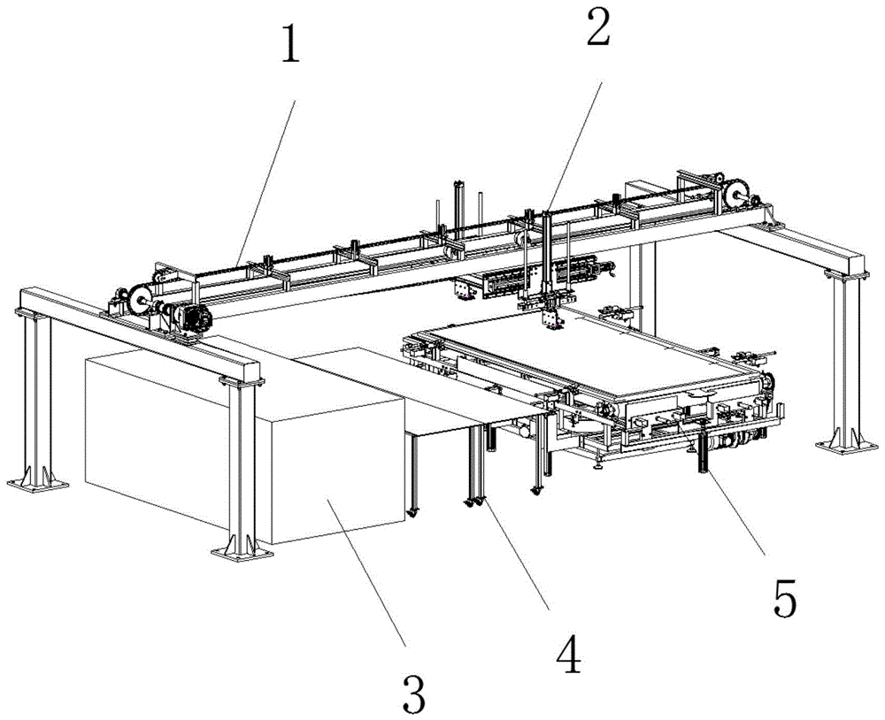
FIG. 1 is a schematic view of the overall structure of the present invention;
FIG. 2 is a schematic structural view of a truss mechanism and a straightening mechanism according to the present invention;
FIG. 3 is a schematic structural view of a centering mechanism of the present invention;
FIG. 4 is a schematic view of an edge-finding correction station according to the present invention;
FIG. 5 is a schematic view of the gripping assembly of the present invention shown in FIG. 1;
FIG. 6 is a schematic view of the gripping assembly of the present invention, shown in FIG. 2;
FIG. 7 is a schematic view of the gripping assembly of the present invention shown in FIG. 3;
FIG. 8 is a schematic view of the gripping assembly of the present invention 4;
fig. 9 is a schematic view 4 of the transportation and straightening state of the bamboo curtain.
In the drawings, the components represented by the respective reference numerals are listed below:
1-a truss mechanism, 11-a gantry vertical frame, 12-a channel steel track, 13-a sprocket bearing seat, 14-a sprocket shaft, 15-a fixed sprocket, 16-a driving motor, 17-a transmission chain, 2-a straightening mechanism, 21-a horizontal sliding table assembly, 22-a vertical lifting assembly, 221-a lifting mounting plate, 222-a lifting cylinder, 223-a lifting mounting frame, 224-a limiting slide bar, 23-a clamping assembly, 3-a raw material placing table, 4-an edge finding correcting table, 41-a correcting table, 42-a universal wheel, 43-a detection hole, 44-a detection sensor and 5-a production line placing table;
231-bracket mounting plate, 232-sliding rail sliding block assembly, 233-translation mounting plate, 234-translation speed reducing motor, 235-driving gear, 236-horizontal mounting plate, 237-abdicating sliding groove, 238-supporting side plate, 239-fixing sliding rod, 2310-guiding mounting plate, 2311-roller, 2312-resetting pressure spring, 2313-swinging speed reducing motor, 2314-clamping hook plate, 2315-bolt hole, 2316-first limit switch, 2317-second limit switch, 2318-limit bolt and 2319-fixing rack.
Detailed Description
The technical solutions in the embodiments of the present invention will be clearly and completely described below with reference to the drawings in the embodiments of the present invention, and it is obvious that the described embodiments are only a part of the embodiments of the present invention, and not all of the embodiments. All other embodiments, which can be derived by a person skilled in the art from the embodiments given herein without making any creative effort, shall fall within the protection scope of the present invention.
Referring to fig. 1, the present invention provides a technical solution: the utility model provides a spread curtain frock structure which characterized in that: mainly include truss mechanism 1, truss mechanism 1 inner chamber below is installed and is ajusted mechanism 2, and mechanism 2 of ajusting can remove about truss mechanism 1, and mechanism 2 of ajusting includes the horizontal slip table subassembly 21 of both sides around, installs vertical lifting unit 22 on the horizontal slip table subassembly 21, and the bottom of vertical lifting unit 22 is installed and is got subassembly 23, and truss mechanism 1's inner chamber below is provided with the raw materials side by side and places platform 3, seeks limit correction platform 4 and assembly line and place platform 5.
Example 1:
referring to fig. 2-3, the truss mechanism 1 includes gantry stands 11 disposed on the left and right sides, two sets of channel steel rails 12 arranged in parallel in the front and back are fixedly disposed between the tops of the gantry stands 11 on the two sides, the openings of the two sets of channel steel rails 12 are oppositely disposed, sprocket bearing seats 13 are respectively disposed at the two ends of the channel steel rails 12, fixed sprockets 15 are rotatably mounted on the sprocket bearing seats 13 through sprocket shafts 14, a driving motor 16 for driving the sprocket shafts 14 is mounted at the top of the gantry stand 11 on one side, and a non-closed transmission chain 17 is disposed between the fixed sprockets 15 on the two sides; the centering mechanism 2 comprises a centering rack 24 of a rectangular mechanism, the horizontal sliding table assemblies 21 are respectively arranged on the front side and the rear side of the centering rack 24, two pairs of pulleys 25 which are respectively in sliding embedded with the two groups of channel steel tracks 12 are arranged at the top of the centering rack 24, and chain fixing plates 26 which are used for being fixed with two ends of the transmission chain 17 are respectively arranged on the left side and the right side of the centering rack 24;
in actual work, the driving motor 16 rotates to drive the fixed chain wheel 15 on the left side to rotate, so that the driving chain 17 is driven to roll, the driving chain 17 is of an open structure, two ends of the driving chain 17 are fixed to the left side and the right side of the straightening rack 24 through the chain fixing plates 26 respectively, when the driving motor 16 rotates, power is provided for left-right translation of the straightening rack 24 through transmission of the fixed chain wheel 15 and the driving chain 17, in addition, the top of the straightening rack 24 is in sliding fit with the channel steel rails 12 through the pulleys 25, the straightening rack 24 can be supported to move left and right on the truss mechanism 1, the openings of the two groups of channel steel rails 12 are oppositely arranged, the pulleys 25, namely the straightening rack 24, can be limited front and back, the whole straightening mechanism 2 is ensured to move along a straight line, and the accuracy and the stability of the structure are improved.
Further, the horizontal sliding table assembly 21 is a screw rod sliding table driven by a stepping motor, the vertical lifting assembly 22 comprises a lifting mounting plate 221 mounted on a movable slider at the front side of the horizontal sliding table assembly 21, a lifting cylinder 222 is vertically mounted in the middle of the lifting mounting plate 221, a lifting mounting frame 223 is mounted at a bottom telescopic end of the lifting cylinder 222, limit slide bars 224 are fixedly mounted on the left side and the right side of the top of the lifting mounting frame 223 respectively, the upper ends of the limit slide bars 224 penetrate through the lifting mounting plate 221 and are slidably mounted with the lifting mounting plate 221 through linear bearings, and the clamping assembly 23 is fixedly mounted at the bottom of the lifting mounting plate 221;
when the bamboo curtain clamping device works actually, the horizontal sliding table assembly 21 is driven by a stepping motor, the horizontal sliding table assemblies 21 on the front side and the rear side can independently run, when the horizontal sliding table assembly 21 on one side translates, the projection angle of the connecting line of the two groups of clamping assemblies 23 on the bottom of the horizontal sliding table assembly on the horizontal plane generates corresponding linear change, and the bamboo curtain clamped by the clamping assemblies 23 can be swung through translation of the horizontal sliding table assembly 21 on one side;
the lifting mounting rack 223 and the clamping component 23 arranged at the bottom of the lifting mounting rack 223 can be driven to move up and down through the telescopic motion of the lifting cylinder 222, so that the bamboo curtain can be lifted and dropped;
example 2: referring to fig. 5-8, the clamping assembly 23 includes a bracket mounting plate 231, a sliding rail slider assembly 232 and a fixed rack 2319 are horizontally disposed on the front side of the bracket mounting plate 231, a translation mounting plate 233 is fixedly mounted on the front side of a slider in the sliding rail slider assembly 232, a translation speed-reducing motor 234 is mounted on the front side of the translation mounting plate 233, an output end of the translation speed-reducing motor 234 penetrates through the translation mounting plate 233 and then is sleeved with a driving gear 235, and the driving gear 235 is engaged with the fixed rack 233;
the lower end of the translation mounting plate 233 is vertically connected with a horizontal mounting plate 236, the horizontal mounting plate 236 is provided with a yielding chute 237 along the left-right direction, the left side and the right side of the top of the yielding chute 237 are fixedly provided with supporting side plates 238, a fixed slide bar 239 is transversely and fixedly arranged between the supporting side plates 238 at two ends, two guide mounting plates 2310 which are distributed at intervals front and back are arranged in the yielding chute 237, four rollers 2311 are arranged between the guide mounting plates 2310 in a rectangular array shape, the inner cavity of each roller 2311 is rotatably mounted with the guide mounting plates 2310 through penetrating bolts, the four rollers 2311 are symmetrically distributed at the upper side and the lower side of the fixed slide bar 239 in pairs and are in sliding fit with the fixed slide bar 239, a reset pressure spring 2312 is sleeved on the outer wall of the fixed slide bar 239 and positioned at the left side of the roller 2311, a swinging speed reducing motor 2313 is mounted on the front side wall of the guide mounting plate 2310, and the output end of the swinging speed reducing motor 2313 extends into the two guide mounting plates 2310, and sleeved with a clamping hook plate 2314;
the support mounting plate 231 is an L-shaped plate with an upward short side, and the top of the support mounting plate 231 is provided with a bolt hole 2315 fixedly mounted with outer wall equipment and used for being fixedly mounted with an external main frame in a matched manner through a bolt; first limit switches 2316 are symmetrically arranged on the left side and the right side of the front side wall of the support mounting plate 231 and are used for limiting the stroke of the translation mounting plate 233; a second limit switch 2317 is installed on the left side of the top of the horizontal installation plate 236 and used for limiting the stroke of the guide installation plate 2310; the guide mounting plate 2310 is a L-shaped plate with a downward short edge, the bottom short edges of the two guide mounting plates 2310 face away from the front side and the rear side, guide chamfers are arranged on the left and right sides of the short edges of the bottoms of the two guide mounting plates 2310, a groove structure is arranged on one side of the lower end of the clamping hook plate 2314, and the height of the groove structure is lower than that of the bottom of the guide mounting plate 2310. During actual use, the bottoms of the guide mounting plates 2310 at the front side and the rear side are firstly moved to be attached to and contacted with the upper surface of the stacked products, and the groove structures below the clamping hook plates 2314 are clamped between the first layer of products and the second layer of products along with the translation of the structures, so that clamping is realized; a limiting bolt 2318 is arranged on the front side wall of the guide mounting plate 2310, after the clamping hook plate 2314 rotates clockwise to be in a horizontal state, the side edge of the clamping hook plate 2314 is abutted to the limiting bolt 2318, and the clamping hook plate 2314 swings upwards in a rotating mode to play a limiting role;
the device is fixedly installed with the lifting installation frame 223 through the support installation plate 231, when in use, the whole mechanism is placed above the side of the stacked bamboo curtain, the bottom of the guide installation plate 2310 on the front side and the rear side is moved to be attached and contacted with the upper surface of the stacked products, the groove structure below the clamping hook plate 2314 is clamped between the first layer of products and the second layer of products along with the structure translation, the clamping is realized, the swinging speed reducing motor 2313 drives the clamping hook plate 2314 to rotate and extend out and into the gap of the bamboo curtain, the translation speed reducing motor 234 drives the driving gear 235 to be meshed and rolled relative to the fixed gear strip 2319, the translation installation plate 233 and the whole hook mechanism installed on the translation installation plate 233 are translated, when the groove structure below the clamping hook plate 2314 hooks the braided wire of the bamboo curtain, the guide installation plate 2310 and the clamping hook plate 2314 installed on the guide installation plate 2310 continue to be translated, since the clamping hook plate 2314 hooks the braided wire to stay in place, then the side edge of the guide mounting plate 2310 touches and presses the second limit switch 2317, the translation speed reducing motor 234 stops running, the whole device mechanism is lifted through lifting the outer wall rack, and the bamboo curtain is grabbed.
Example 3:
please refer to fig. 4: the edge-searching correction table 4 comprises a correction table 41, universal wheels 42 are arranged at the bottoms of four legs of the correction table 41, detection holes 43 are arranged at the front and back of one side edge of the correction table 41 close to the raw material placing table 3 at intervals, and detection sensors 44 are arranged at the positions, corresponding to the detection holes 43, of the bottom surface of the correction table 41;
when the bamboo curtain is clamped on the correcting table 41 in an inclined state, the connecting line between the side edge of the bamboo curtain and the two detecting sensors 44 is not parallel, the positions of the two detecting sensors 44 are used as the reference for the straightness of the side edge of the bamboo curtain, and the bamboo curtain clamped by the clamping assembly 23 can be swung and rotated by the translation of the single-side horizontal sliding table assembly 21.
The specific application operation method of the invention comprises the following steps:
s1: the driving motor 16 is controlled to move the aligning mechanism 2 to be right above the raw material placing table 3;
s2: the vertical lifting components 22 on the front side and the rear side are synchronously controlled to drive the clamping components 23 to descend to be in contact with the bamboo curtains, and the positions of the clamping components 23 on the two sides are shown as clamping points c on the raw material placing table 3 in fig. 9;
s3: synchronously controlling the clamping components 23 on the front side and the rear side to hook the bamboo curtains;
s4: synchronously operating the vertical lifting components 22 at the front side and the rear side to drive the clamping components 23 to ascend so as to lift the bamboo curtain;
s5: operating the driving motor 16 to move the correcting mechanism 2 above the detection sensor 44;
s6: the vertical lifting components 22 on the front side and the rear side are synchronously controlled to drive the clamping components 23 to descend until the bamboo curtains contact with the top surface of the edge finding correction table 4;
s7: the driving motor 16 is controlled to drive the straightening mechanism 2 to move rightwards until one side edge of the bead curtain far away from the traveling direction just passes over one of the detection sensors 44;
s8: independently controlling the bead curtain not to cross the horizontal sliding table assembly 21 on one side of the detection sensor 44 until the side edge of the bead curtain just crosses the detection sensors 44 on the two sides, and finishing the straightening; at this time, the two groups of clamping assemblies 23 are staggered from left to right by a certain distance, as shown by a clamping point c on the edge-finding correction table 4 in fig. 9;
s9: synchronously operating the vertical lifting components 22 at the front side and the rear side to drive the clamping components 23 to ascend so as to lift the bamboo curtain;
s10: the driving motor 16 is controlled to move the aligning mechanism 2 to the upper part of the assembly line placing platform 5;
s11: the vertical lifting components 22 on the front side and the rear side are synchronously controlled to drive the clamping components 23 to descend until the bamboo curtains contact with the top surface of the assembly line placing table 5;
s12: the clamping assemblies 23 on the front side and the rear side are synchronously controlled to release the bamboo curtains on the assembly line placing table 5, and the two groups of clamping assemblies 23 are arranged in parallel and level from front to rear after being reset, as shown by a clamping point c in fig. 9 and on the assembly line placing table 5.
In the description of the invention, it is to be understood that the terms "coaxial", "bottom", "one end", "top", "middle", "other end", "upper", "one side", "top", "inner", "front", "center", "two ends", and the like, indicate orientations or positional relationships based on those shown in the drawings, and are used only for convenience in describing the invention and for simplicity in description, and do not indicate or imply that the device or element being referred to must have a particular orientation, be constructed in a particular orientation, and be operated, and thus, are not to be construed as limiting the invention.
In the present invention, unless otherwise specifically stated or limited, the terms "mounted," "disposed," "connected," "fixed," "screwed" and the like are to be construed broadly, e.g., as being fixedly connected, detachably connected, or integrated; can be mechanically or electrically connected; the terms may be directly connected or indirectly connected through an intermediate, and may be communication between two elements or interaction relationship between two elements, unless otherwise specifically defined, and the specific meaning of the terms in the invention is understood by those skilled in the art according to specific situations.
Although embodiments of the present invention have been shown and described, it will be appreciated by those skilled in the art that changes, modifications, substitutions and alterations can be made in these embodiments without departing from the principles and spirit of the invention, the scope of which is defined in the appended claims and their equivalents.