CN111851787A - A structure of joints connected by side bars of longitudinal and transverse walls of a superimposed shear wall with openings - Google Patents
A structure of joints connected by side bars of longitudinal and transverse walls of a superimposed shear wall with openings Download PDFInfo
- Publication number
- CN111851787A CN111851787A CN202010537586.0A CN202010537586A CN111851787A CN 111851787 A CN111851787 A CN 111851787A CN 202010537586 A CN202010537586 A CN 202010537586A CN 111851787 A CN111851787 A CN 111851787A
- Authority
- CN
- China
- Prior art keywords
- prefabricated wall
- vertical
- wall
- opening
- steel bars
- Prior art date
- Legal status (The legal status is an assumption and is not a legal conclusion. Google has not performed a legal analysis and makes no representation as to the accuracy of the status listed.)
- Granted
Links
Images


Classifications
-
- E—FIXED CONSTRUCTIONS
- E04—BUILDING
- E04B—GENERAL BUILDING CONSTRUCTIONS; WALLS, e.g. PARTITIONS; ROOFS; FLOORS; CEILINGS; INSULATION OR OTHER PROTECTION OF BUILDINGS
- E04B2/00—Walls, e.g. partitions, for buildings; Wall construction with regard to insulation; Connections specially adapted to walls
- E04B2/56—Load-bearing walls of framework or pillarwork; Walls incorporating load-bearing elongated members
-
- E—FIXED CONSTRUCTIONS
- E04—BUILDING
- E04B—GENERAL BUILDING CONSTRUCTIONS; WALLS, e.g. PARTITIONS; ROOFS; FLOORS; CEILINGS; INSULATION OR OTHER PROTECTION OF BUILDINGS
- E04B2/00—Walls, e.g. partitions, for buildings; Wall construction with regard to insulation; Connections specially adapted to walls
-
- E—FIXED CONSTRUCTIONS
- E04—BUILDING
- E04C—STRUCTURAL ELEMENTS; BUILDING MATERIALS
- E04C5/00—Reinforcing elements, e.g. for concrete; Auxiliary elements therefor
- E04C5/16—Auxiliary parts for reinforcements, e.g. connectors, spacers, stirrups
- E04C5/162—Connectors or means for connecting parts for reinforcements
- E04C5/163—Connectors or means for connecting parts for reinforcements the reinforcements running in one single direction
- E04C5/165—Coaxial connection by means of sleeves
-
- E—FIXED CONSTRUCTIONS
- E04—BUILDING
- E04G—SCAFFOLDING; FORMS; SHUTTERING; BUILDING IMPLEMENTS OR AIDS, OR THEIR USE; HANDLING BUILDING MATERIALS ON THE SITE; REPAIRING, BREAKING-UP OR OTHER WORK ON EXISTING BUILDINGS
- E04G21/00—Preparing, conveying, or working-up building materials or building elements in situ; Other devices or measures for constructional work
- E04G21/12—Mounting of reinforcing inserts; Prestressing
Landscapes
- Engineering & Computer Science (AREA)
- Architecture (AREA)
- Civil Engineering (AREA)
- Structural Engineering (AREA)
- Physics & Mathematics (AREA)
- Electromagnetism (AREA)
- Mechanical Engineering (AREA)
- Reinforcement Elements For Buildings (AREA)
Abstract
Description
技术领域technical field
本发明属于建筑技术领域,涉及叠合剪力墙,特别涉及一种带洞口叠合剪 力墙纵横墙侧面出筋连接节点构造。The invention belongs to the technical field of construction, relates to a superimposed shear wall, and in particular relates to a longitudinal and transverse wall side reinforced connection node structure of a superimposed shear wall with holes.
背景技术Background technique
叠合剪力墙加工、安装精度要求低,可有效降低预制墙连接成本,连接质 量可控,是一类符合当下中国国情的装配式混凝土结构体系,其代表性体系为 双面叠合剪力墙结构。Laminated shear walls have low processing and installation accuracy requirements, which can effectively reduce the cost of prefabricated wall connection, and the connection quality is controllable. It is a type of fabricated concrete structure system that conforms to the current Chinese national conditions. wall structure.
双面叠合剪力墙结构中,纵、横向预制墙多通过竖向后浇段实现连接,尤 其是住宅建筑南北立面,存在大量的带洞口预制墙,且一侧墙肢长度较短、长 度多低于800mm,需设置预制边缘构件方可实现预制墙拆分,此时带洞口预制 墙的预制边缘构件将与竖向后浇段直接连接,该位置现有节点构造中带洞口预 制墙空腔内需布设水平连接钢筋实现带洞口预制墙与竖向后浇段的连接,且带 洞口预制墙的预制边缘构件空腔内需布设连接钢筋与预制墙内边缘构件竖向钢 筋搭接连接,导致预制墙内边缘构件竖向钢筋搭接范围内水平连接钢筋皮净距 仅为30mm,水平连接钢筋外皮与预制墙混凝土壁板内侧净距仅为25mm,空 腔内无法插入混凝土振捣棒,后浇混凝土无法振捣,实际工程中大范围采用自 密实混凝土成本较高。In the double-sided superimposed shear wall structure, the vertical and horizontal prefabricated walls are mostly connected by the vertical post-casting section, especially on the north and south facades of residential buildings, there are a large number of prefabricated walls with openings, and the length of one side wall is short, The length is mostly less than 800mm, and prefabricated edge members need to be installed to realize prefabricated wall splitting. At this time, the prefabricated edge members of the prefabricated wall with openings will be directly connected to the vertical post-cast section, and the prefabricated walls with openings in the existing node structure at this location are Horizontal connecting steel bars need to be laid in the cavity to realize the connection between the prefabricated wall with openings and the vertical post-casting section, and the prefabricated edge members of the prefabricated wall with openings need to be laid in the cavity of the prefabricated wall. The clear distance between the horizontal connecting steel bar skin and the inner side of the prefabricated wall concrete siding is only 30mm within the vertical steel bar overlap range of the inner edge members of the prefabricated wall. The poured concrete cannot be vibrated, and the cost of using self-compacting concrete on a large scale in practical projects is relatively high.
发明内容SUMMARY OF THE INVENTION
为了克服上述现有带洞口叠合剪力墙纵横墙连接节点构造的缺点,本发明 的目的在于提供一种带洞口叠合剪力墙纵横墙侧面出筋连接节点构造,在带洞 口叠合剪力墙纵横墙连接节点位置,通过带洞口预制墙侧面伸出钢筋与竖向后 浇段连接,带洞口预制墙空腔内无需布设专门水平连接钢筋,可避免现有构造 中水平连接钢筋与带洞口预制墙空腔内边缘构件竖向钢筋附加连接钢筋相互干 扰的问题,可保证带洞口预制墙边缘构件位置空腔内后浇混凝土浇筑时的振捣 空间,有利于带洞口预制墙边缘构件位置后浇混凝土的质量控制,保证结构关 键受力部位的施工质量、改善结构抗震性能。In order to overcome the above-mentioned shortcomings of the existing longitudinal and transverse wall connection node structures of superimposed shear walls with holes, the purpose of the present invention is to provide a structure of connecting nodes with ribs on the sides of superimposed shear walls with holes. The vertical and horizontal wall connection nodes of the force wall are connected with the vertical post-casting section through the lateral extension of the prefabricated wall with openings. There is no need to lay special horizontal connecting steel bars in the cavity of the prefabricated wall with openings, which can avoid the horizontal connecting steel bars and belts in the existing structure. The problem of mutual interference between the vertical reinforcing bars of the edge members in the cavity of the prefabricated wall with the opening and the mutual interference of the additional connecting steel bars can ensure the vibration space when the post-cast concrete is poured in the cavity of the edge member of the prefabricated wall with the opening, which is beneficial to the position of the edge member of the prefabricated wall with the opening. The quality control of post-cast concrete ensures the construction quality of the key stress-bearing parts of the structure and improves the seismic performance of the structure.
为了实现上述目的,本发明采用的技术方案是:In order to achieve the above object, the technical scheme adopted in the present invention is:
一种带洞口叠合剪力墙纵横墙侧面出筋连接节点构造,主要包括带洞口预 制墙1、无洞口预制墙2和竖向后浇段3,带洞口预制墙1和无洞口预制墙2均 包括两层预制混凝土壁板14,两预制混凝土壁板14之间形成空腔15,其特征 在于,带洞口预制墙1洞口一侧设置预制墙边缘构件区域11且与竖向后浇段3 直接连接,带洞口预制墙1的预制墙边缘构件箍筋116采用组合箍筋,组合箍 筋的开口箍筋113在带洞口预制墙1端部弯折后经空腔15伸入竖向后浇段3, 借助开口箍筋113伸出段实现纵横墙连接节点位置带洞口预制墙1与竖向后浇 段3的连接,带洞口预制墙1的空腔15内无需布设水平连接钢筋,避免现有构 造中水平连接钢筋与带洞口预制墙空腔内边缘构件竖向钢筋附加连接钢筋相互 干扰的问题。A superimposed shear wall with an opening is a longitudinal and transverse wall side reinforcement connection node structure, which mainly includes a prefabricated wall with openings 1, a prefabricated wall without
所述开口箍筋113开口端位于竖向后浇段3内,在带洞口预制墙1侧边端 部内侧从预制混凝土壁板14内壁伸入空腔15内,经由空腔15伸入竖向后浇段 3,而非直接从预制混凝土壁板14侧面伸入竖向后浇段3,可实现预制墙生产过 程边模不开孔,有利于预制墙模具的标准化、通用化,且可避免开口箍筋113 与边模的对位问题,提高预制墙生产效率;开口箍筋113位于竖向后浇段3内 的端部设置弯钩,以增强其在竖向后浇段内的锚固性能。The open end of the
在预制墙边缘构件区域11远离竖向后浇段3的预制混凝土壁板14内配置 预制墙边缘构件竖向受力钢筋111,靠近开口箍筋113弯折位置配置预制墙边缘 构件竖向构造钢筋112,在空腔15楼面位置布设预制墙边缘构件竖向受力钢筋 双排附加连接钢筋115与上下层预制墙边缘构件竖向受力钢筋111搭接连接; 或仅在预制墙边缘构件区域11内配置预制墙边缘构件竖向构造钢筋112与开口 箍筋113、预制墙边缘构件拉筋114形成钢筋骨架,在预制墙边缘构件区域11 的空腔15内配置单排大直径边缘构件竖向受力钢筋117,大直径边缘构件竖向 受力钢筋117在空腔15内上下贯通、沿墙体厚度中线布置,参与结构受力计算。In the prefabricated wall
所述预制墙边缘构件竖向受力钢筋111和大直径边缘构件竖向受力钢筋117 的配筋总面积满足剪力墙抗弯承载力验算要求,或按照同一强度等级钢筋等面 积代换的原则代替传统剪力墙的多根边缘构件竖向钢筋,或满足现行规范对边 缘构件竖向钢筋的最小配筋率要求;上下层大直径边缘构件竖向受力钢筋117 采用钢筋接头32连接,钢筋接头32布置在同一高度或错开一定距离。The total reinforcement area of the vertical
所述无洞口预制墙2中布设水平分布钢筋121,其中:水平分布钢筋121靠 近竖向后浇段3的一端不伸出,无洞口预制墙2与竖向后浇段3通过穿设于其 空腔15内的水平连接钢筋35实现连接;或者,水平分布钢筋121靠近竖向后 浇段3的一端在无洞口预制墙2端部弯折后经空腔15伸入竖向后浇段3,借助 弯折伸出水平分布钢筋124实现纵横墙连接节点位置无洞口预制墙2与竖向后 浇段3的连接,不在空腔15内布设水平连接钢筋35,此时无洞口预制墙2所在 一侧墙肢的边缘构件区域全部采用现浇边缘构件。The horizontal
所述无洞口预制墙2所在一侧墙肢的边缘构件区域全部采用现浇边缘构件, 此时无洞口预制墙2不设置预制墙边缘构件区域11;或者,无洞口预制墙2所 在一侧墙肢的边缘构件区域采用预制墙边缘构件区域11和竖向后浇段3组合实 现,此时竖向后浇段3宽度与墙体厚度等同,无洞口预制墙2端部设置预制墙 边缘构件区域11,预制墙边缘构件区域11内配置不伸出无洞口预制墙2的小直 径的预制墙边缘构件竖向构造钢筋112,不配置普通规格的预制墙边缘构件竖向 受力钢筋111,配置预制墙边缘构件箍筋116或预制墙边缘构件拉筋114对预制 墙边缘构件区域11混凝土形成箍筋约束作用,在空腔15楼面位置布设预制墙 边缘构件竖向构造钢筋单排附加连接钢筋118与上下层预制墙边缘构件竖向构 造钢筋112搭接连接。The edge component area of the side wall where the
所述无洞口预制墙2端部设置预制墙边缘构件区域11时,原配置于预制墙 边缘构件区域11的边缘构件竖向钢筋集中配置于竖向后浇段3内,竖向后浇段 边缘构件竖向钢筋31、预制墙边缘构件竖向构造钢筋112的总面积满足剪力墙 抗弯承载力验算要求,或按照同一强度等级钢筋等面积代换的原则代替传统剪 力墙的多根边缘构件竖向钢筋,或满足现行规范对边缘构件竖向钢筋的最小配 筋率要求;此时竖向后浇段边缘构件竖向钢筋31采用钢筋接头32连接,钢筋 接头32布置在同一高度或错开一定距离。When the prefabricated wall
所述大直径边缘构件竖向受力钢筋117的直径不小于14mm;所述预制墙 边缘构件竖向构造钢筋112的直径不大于10mm,设置于预制混凝土壁板14内, 根数根据预制墙边缘构件区域11的范围设置;预制墙边缘构件区域11长度不 大于300mm时,设置4根预制墙边缘构件竖向构造钢筋112;预制墙边缘构件 区域11长度介于300~600mm时,设置6根预制墙边缘构件竖向构造钢筋112。The diameter of the vertical force-bearing
所述水平连接钢筋35穿设于竖向后浇段3与无洞口预制墙2之间,直径不 小于无洞口预制墙2内水平分布钢筋121的直径,沿竖向的间距不大于水平分 布钢筋121的间距。The horizontal connecting
在空腔15内的预制墙竖向分布钢筋底部搭接区段17,水平连接钢筋35采 用U形钢筋,开口端伸入无洞口预制墙2内,封闭端与竖向后浇段边缘构件箍 筋33绑扎定位;在空腔15内预制墙竖向分布钢筋底部搭接以外区段18,水平 连接钢筋35采用封闭环状钢筋、开口端设弯钩的U形钢筋或U形钢筋。The prefabricated wall in the
与现有技术相比,本发明的有益效果是:Compared with the prior art, the beneficial effects of the present invention are:
(1)本发明借助带洞口预制墙伸出开口箍筋实现纵横墙连接节点位置带洞 口预制墙与竖向后浇段的连接,带洞口预制墙的空腔内无需布设专门水平连接 钢筋,可避免现有构造中水平连接钢筋与带洞口预制墙空腔内边缘构件竖向钢 筋附加连接钢筋相互干扰的问题,便于预制墙边缘构件区域空腔内后浇混凝土 的振捣。(1) The present invention realizes the connection between the prefabricated wall with an opening and the vertical post-casting section at the connection node position of the vertical and horizontal walls by extending the opening stirrups from the prefabricated wall with the opening. The problem of mutual interference between the horizontal connecting steel bar and the vertical connecting steel bar of the inner edge member of the prefabricated wall cavity with the opening in the existing structure is avoided, and the vibration of the post-cast concrete in the cavity of the prefabricated wall edge member region is facilitated.
(2)本发明开口箍筋不直接从预制混凝土壁板侧面伸出,可实现预制墙生 产过程边模不开孔,有利于预制墙模具的标准化、通用化,且可避免预制墙边 缘构件开口箍筋与边模的对位问题,提高预制墙生产效率。(2) The opening stirrups of the present invention do not directly protrude from the side of the prefabricated concrete wall panel, so that the side molds of the prefabricated wall can be produced without opening holes, which is beneficial to the standardization and generalization of the prefabricated wall molds, and can avoid the opening of the prefabricated wall edge components. The alignment of stirrups and side molds improves the production efficiency of prefabricated walls.
(3)本发明带洞口预制墙的空腔内无需布设专门水平连接钢筋,钢筋用量 少,现场钢筋绑扎量小,可减少一定的成本。(3) The cavity of the prefabricated wall with the opening of the present invention does not need to lay out special horizontal connecting steel bars, the amount of steel bars is small, and the amount of on-site steel bar binding is small, which can reduce a certain cost.
(4)本发明纵横墙连接节点处竖向后浇段尺寸可控制在与墙体厚度等同, 竖向后浇段范围明显减小,且竖向后浇段内竖向钢筋、箍筋及水平连接钢筋构 造简单,竖向后浇段钢筋绑扎效率高、现场支模量小,可大大提高现场施工效 率。(4) The dimension of the vertical post-cast section at the connection node of the vertical and horizontal walls of the present invention can be controlled to be equal to the thickness of the wall, the range of the vertical post-cast section is significantly reduced, and the vertical steel bars, stirrups and horizontal bars in the vertical post-cast section can be controlled to be equal to the thickness of the wall. The connecting steel bar has a simple structure, the vertical post-casting section steel bar binding efficiency is high, and the on-site support modulus is small, which can greatly improve the on-site construction efficiency.
(5)本发明带洞口预制墙内可采用空腔内贯通的大直径竖向钢筋避免边缘 构件竖向钢筋的间接搭接,有助于控制边缘构件竖向钢筋用量,且钢筋机械连 接技术成熟、传力性能好,可保证墙体在大变形下的抗震性能。(5) In the prefabricated wall with holes of the present invention, large-diameter vertical steel bars that penetrate through the cavity can be used to avoid the indirect overlap of the vertical steel bars of the edge members, which is helpful to control the amount of vertical steel bars of the edge members, and the mechanical connection technology of steel bars is mature , Good force transmission performance, which can ensure the seismic performance of the wall under large deformation.
附图说明Description of drawings
图1为本发明应用于叠合剪力墙结构L形节点、一侧预制墙为带洞口预制 墙的典型构造的三维示意图,其中带洞口预制墙的边缘构件竖向钢筋采用间接 搭接连接。Fig. 1 is the three-dimensional schematic diagram that the present invention is applied to the L-shaped node of superimposed shear wall structure, one side prefabricated wall is the typical structure of prefabricated wall with opening, wherein the vertical reinforcement of edge member of prefabricated wall with opening adopts indirect lap connection.
图2为图1中带洞口预制墙的三维示意图。FIG. 2 is a three-dimensional schematic diagram of the prefabricated wall with openings in FIG. 1 .
图3为图2中C-C截面示意图。FIG. 3 is a schematic cross-sectional view of C-C in FIG. 2 .
图4为图1所示L形连接节点预制墙竖向分布钢筋底部搭接区段A-A截面 示意图。Figure 4 is a schematic cross-sectional view of the lap joint section A-A at the bottom of the vertically distributed steel bars of the prefabricated wall of the L-shaped connection node shown in Figure 1 .
图5为图1所示预制边缘构件区域水平接缝的构造示意图,其中空腔内布 设预制墙边缘构件竖向受力钢筋双排附加连接钢筋与预制墙边缘构件竖向受力 钢筋搭接连接。Figure 5 is a schematic diagram of the structure of the horizontal joint in the area of the prefabricated edge member shown in Figure 1, wherein double rows of additional connecting steel bars for vertical stress on the edge member of the prefabricated wall are arranged in the cavity to overlap and connect with the vertical stress bar on the edge member of the prefabricated wall .
图6为图1所示L形连接节点预制墙竖向分布钢筋底部搭接以外区段B-B 截面示意图,其中水平连接钢筋采用环状封闭钢筋。Fig. 6 is a schematic cross-sectional view of the section B-B of the prefabricated wall of the L-shaped connecting node prefabricated wall shown in Fig. 1 except for the bottom overlap of the bottom of the vertical distribution, wherein the horizontal connecting reinforcing bars are annular closed reinforcing bars.
图7为图1所示L形连接节点预制墙竖向分布钢筋底部搭接以外区段B-B 截面示意图,其中水平连接钢筋采用U形钢筋、开口端设弯钩。Figure 7 is a schematic cross-sectional view of the section B-B of the prefabricated wall of the L-shaped connection node prefabricated wall shown in Figure 1 except for the bottom overlap of the bottom lap, wherein the horizontal connection reinforcement adopts U-shaped reinforcement and the open end is provided with hooks.
图8为图1所示L形连接节点预制墙竖向分布钢筋底部搭接以外区段B-B 截面示意图,其中水平连接钢筋采用U形钢筋。Fig. 8 is a schematic cross-sectional view of the section B-B of the prefabricated wall of the prefabricated wall of the L-shaped connection node shown in Fig. 1 except for the bottom overlap of the vertically distributed steel bars, wherein the horizontal connection steel bars are U-shaped steel bars.
图9为图1所示L形连接节点的改进型一,其中带洞口预制墙的边缘构件 空腔内配置大直径边缘构件竖向受力钢筋。Figure 9 is an improved version 1 of the L-shaped connection node shown in Figure 1, wherein the edge member cavity of the prefabricated wall with openings is equipped with a large-diameter edge member vertical stress steel bar.
图10为图9中带洞口预制墙的三维示意图。FIG. 10 is a three-dimensional schematic diagram of the prefabricated wall with openings in FIG. 9 .
图11为图10中E-E截面示意图。FIG. 11 is a schematic cross-sectional view of E-E in FIG. 10 .
图12为图9所示L形连接节点预制墙竖向分布钢筋底部搭接区段D-D截面 示意图。Figure 12 is a schematic cross-sectional view of the D-D section of the lap joint section at the bottom of the vertically distributed reinforcement bars of the prefabricated wall of the L-shaped connection node shown in Figure 9 .
图13、图14为本发明的改进型二,其中无洞口侧预制墙水平分布钢筋弯折 伸出。Fig. 13 and Fig. 14 are the second modification of the present invention, wherein the horizontally distributed reinforcing bars of the prefabricated wall on the side without openings are bent and extended.
图15、图16为本发明的改进型三,仅设置宽度与墙体厚度等同的小尺寸竖 向后浇段。Figure 15 and Figure 16 show the third modification of the present invention, only a small-sized vertical post-casting section with a width equal to the thickness of the wall is provided.
图17为图15、图16中竖向分布钢筋122与竖向分布钢筋双排附加连接钢 筋123的搭接连接构造示意图。Figure 17 is a schematic diagram of the lap connection structure of the vertical
图18、图19为图15、图16的开口箍筋改进型,其中预制墙边缘构件开口 箍筋伸入竖向后浇段的末端设置弯钩。Figures 18 and 19 are the improved open stirrups shown in Figures 15 and 16, wherein a hook is provided at the end of the open stirrup of the prefabricated wall edge member extending into the vertical post-casting section.
图20为叠合剪力墙结构L形节点、一侧预制墙为带洞口预制墙的现有构造 示意图,即本发明的对比例。Fig. 20 is the existing structural schematic diagram of the L-shaped node of the superimposed shear wall structure, and the prefabricated wall on one side is the prefabricated wall with openings, that is, the comparative example of the present invention.
图中:1-带洞口预制墙;2-无洞口预制墙;3-竖向后浇段;11-预制墙边缘构 件区域;12-预制墙洞口区域;13-预制墙墙身区域;14-预制混凝土壁板;15-空 腔;16-钢筋桁架;17-预制墙竖向分布钢筋底部搭接区段;18-预制墙竖向分布 钢筋底部搭接以外区段;111-预制墙边缘构件竖向受力钢筋;112-预制墙边缘构 件竖向构造钢筋;113-开口箍筋;114-预制墙边缘构件拉筋;115-预制墙边缘构 件竖向受力钢筋双排附加连接钢筋;116-预制墙边缘构件箍筋;117-大直径边缘 构件竖向受力钢筋;118-预制墙边缘构件竖向构造钢筋单排附加连接钢筋;121- 水平分布钢筋;122-竖向分布钢筋;123-竖向分布钢筋双排附加连接钢筋;124- 弯折伸出水平分布钢筋;31-竖向后浇段边缘构件竖向钢筋;32-钢筋接头;33- 竖向后浇段边缘构件箍筋;34-竖向后浇段边缘构件拉筋;35-水平连接钢筋;36-安装缝;37-洞口侧水平连接钢筋;41-预制墙底部水平接缝;42-预制墙顶部水 平后浇带;43-预制楼板。In the figure: 1- prefabricated wall with opening; 2- prefabricated wall without opening; 3- vertical post-casting section; 11- prefabricated wall edge component area; 12- prefabricated wall opening area; 13- prefabricated wall body area; 14- Precast concrete siding; 15-cavity; 16-rebar truss; 17-prefabricated wall vertical distribution steel bottom overlap section; 18-precast wall vertical distribution steel bottom overlap section; 111-precast wall edge member Vertical stress bars; 112 - Vertical structural steel bars for prefabricated wall edge members; 113 - Open stirrups; 114 - Prefabricated wall edge members tie bars; - prefabricated wall edge member stirrups; 117-large diameter edge member vertical stress reinforcement; 118-prefabricated wall edge member vertical structural reinforcement single row additional connecting reinforcement; 121-horizontal distribution reinforcement; 122-vertical distribution reinforcement; 123 - Double rows of additional connecting steel bars for vertical distribution; 124- Bending and extending horizontal distribution steel bars; 31- Vertical steel bars for edge members of vertical post-cast sections; 32- Steel bar joints; 33- Stirrups for edge members of vertical post-cast sections ;34- Vertical post-casting section edge member tie bars; 35-Horizontal connecting steel bars; 36-Installation joints; 37-Horizontal connecting steel bars on the side of openings; ; 43 - Prefabricated floor slabs.
具体实施方式Detailed ways
下面结合附图和实施例详细说明本发明的实施方式。The embodiments of the present invention will be described in detail below with reference to the accompanying drawings and examples.
如图1~图19所示,本发明一种带洞口叠合剪力墙纵横墙侧面出筋连接节点 构造,用于叠合剪力墙结构纵横墙连接节点位置,主要包括带洞口预制墙1、无 洞口预制墙2和竖向后浇段3,带洞口预制墙1和无洞口预制墙2均包括两层预 制混凝土壁板14,两预制混凝土壁板14之间形成空腔15,带洞口预制墙1包 括预制墙洞口区域12,无洞口预制墙2包括预制墙墙身区域13。本发明的优化、 改进在于带洞口预制墙1,其预制墙洞口区域12一侧墙肢长度较短,多小于800 mm,因此在该侧端部需设置与竖向后浇段3直接连接的预制墙边缘构件区域 11。As shown in Figures 1 to 19, the present invention is a superimposed shear wall longitudinal and transverse wall side reinforced connection node structure with a hole, which is used for the connection node position of the longitudinal and transverse walls of the superimposed shear wall structure, mainly including a prefabricated wall with a hole 1 , the
带洞口预制墙1的预制墙边缘构件箍筋116采用组合箍筋,组合箍筋由开 口箍筋113和预制墙边缘构件拉筋114组成。开口箍筋113开口端位于竖向后 浇段3内,封闭端位于预制墙边缘构件区域11内,在带洞口预制墙1端部附近 弯折,伸入竖向后浇段3,借助开口箍筋113实现带洞口预制墙1与竖向后浇段 3的连接。带洞口预制墙1的空腔15内无需布设专门水平连接钢筋,避免现有 构造中水平连接钢筋与带洞口预制墙空腔内边缘构件竖向钢筋附加连接钢筋相 互干扰的问题。开口箍筋113可进一步在带洞口预制墙1侧边内侧从预制混凝 土壁板14内壁伸入空腔15内,进而伸出带洞口预制墙1、伸入竖向后浇段3, 而非直接从预制混凝土壁板14侧面伸出,可实现预制墙生产过程边模不开孔, 有利于预制墙模具的标准化、通用化,且可避免预制墙生产过程中开口箍筋113 与边模的对位问题,提高预制墙生产效率。The prefabricated wall
进一步地,可在开口箍筋113伸入竖向后浇段3的端部设置90°或135° 弯钩,以增强其在竖向后浇段3内的锚固性能。Further, a 90° or 135° hook can be provided at the end of the
相应地,带洞口预制墙1的预制墙边缘构件区域11的竖向钢筋可采用两种 构造。其一,边缘构件竖向钢筋可采用搭接连接,在预制墙边缘构件区域11远 离竖向后浇段3的预制混凝土壁板14内配置预制墙边缘构件竖向受力钢筋111, 在空腔15楼面位置布设预制墙边缘构件竖向受力钢筋双排附加连接钢筋115与 上下层预制墙边缘构件竖向受力钢筋111搭接连接,预制墙边缘构件竖向受力 钢筋双排附加连接钢筋115在空腔15内上下不贯通、长度满足钢筋搭接要求, 直径不应小于预制墙边缘构件竖向受力钢筋111;在开口箍筋113弯折位置配置 预制墙边缘构件竖向构造钢筋112,不伸出预制墙,不参与结构受力,直径不宜 大于10mm。Accordingly, the vertical reinforcement of the prefabricated wall
其二,带洞口预制墙1的预制墙边缘构件区域11的竖向钢筋构造也可与申 请人所申请的名称为“空腔内配置大直径边缘构件竖向钢筋的叠合暗柱及预制 墙”的专利一致(预制墙包括叠合暗柱区域和墙身区域,叠合暗柱区域采用所 述叠合暗柱,预制混凝土壁板延伸形成墙身区域,叠合暗柱,包括两侧的预制 混凝土壁板,两预制混凝土壁板之间形成空腔,在预制混凝土壁板中仅配置小 直径的边缘构件竖向构造钢筋与边缘构件箍筋、边缘构件拉筋形成暗柱钢筋骨 架,边缘构件竖向构造钢筋上下端均不伸出预制混凝土壁板、不参与结构受力 计算;在空腔内配置单排大直径竖向钢筋作为边缘构件竖向受力钢筋,参与结 构受力计算,上下层边缘构件竖向受力钢筋在空腔内采用钢筋接头直接连接, 现场浇筑空腔内后浇混凝土)。预制墙边缘构件区域11的预制混凝土壁板14 内仅配置小直径的预制墙边缘构件竖向构造钢筋112(不参与结构受力计算、直 径不宜大于10mm),不配置普通规格的边缘构件竖向钢筋,与开口箍筋113、 预制墙边缘构件拉筋114形成钢筋骨架;在空腔15内靠近预制墙洞口区域12 一侧配置单排大直径边缘构件竖向受力钢筋117,在空腔15内上下贯通、沿墙 体厚度中线布置,参与结构受力计算。当边缘构件竖向钢筋计算配筋面积较大 时,配置两根大直径边缘构件竖向受力钢筋117会导致钢筋直径较大,可在空 腔15内配置三根或三根以上的边缘构件竖向受力钢筋117控制其直径。Secondly, the vertical reinforcement structure of the prefabricated wall
特别地,预制墙边缘构件竖向受力钢筋111、大直径边缘构件竖向受力钢筋117为带洞口预制墙1的预制墙边缘构件区域11的边缘构件竖向受力钢筋,其 配筋总面积应满足剪力墙抗弯承载力验算要求,或按照同一强度等级钢筋等面 积代换的原则代替传统剪力墙的多根边缘构件竖向钢筋,或满足现行规范对边 缘构件竖向钢筋的最小配筋率要求。上下层大直径边缘构件竖向受力钢筋117 采用钢筋接头32连接,钢筋接头32可布置在同一高度,也可错开一定距离。In particular, the vertical stress reinforcement bars 111 of the prefabricated wall edge members and the vertical stress reinforcement bars 117 of the large-diameter edge members are the vertical stress reinforcement bars of the edge members of the prefabricated wall
本发明中,无洞口预制墙2的构造有水平分布钢筋121伸出和不伸出两种 形式。In the present invention, the structure of the
水平分布钢筋121不伸出时,无洞口预制墙2与竖向后浇段3通过穿设于 空腔15内的水平连接钢筋35实现连接。无洞口预制墙2所在一侧墙肢的边缘 构件区域可全部采用现浇边缘构件,此时无洞口预制墙2不设置预制墙边缘构 件区域11,无洞口预制墙2与普通叠合剪力墙构造一致,竖向后浇段3的范围 应包含现行规范建议的无洞口预制墙2所在一侧墙肢的边缘构件范围。When the horizontal
无洞口预制墙2所在一侧墙肢的边缘构件区域也可采用预制墙边缘构件区 域11和竖向后浇段3组合实现,此时竖向后浇段3宽度与墙体厚度等同,此时 带洞口预制墙1与无洞口预制墙2之间应设置安装缝36,安装缝36的宽度不宜 小于20mm,以保证预制墙安装效率及精度,同时用于穿设竖向后浇段3的模 板固定工装。无洞口预制墙2端部设置预制墙边缘构件区域11,预制墙边缘构 件区域11构造与前述专利一致,预制墙边缘构件区域11内配置不伸出预制墙 的小直径预制墙边缘构件竖向构造钢筋112,不配置普通规格的预制墙边缘构件 竖向受力钢筋111,配置预制墙边缘构件箍筋116或预制墙边缘构件拉筋114对预制墙边缘构件区域11的混凝土形成箍筋约束作用,在空腔15楼面位置布设 预制墙边缘构件竖向构造钢筋单排附加连接钢筋118与上下层预制墙边缘构件 竖向构造钢筋112搭接连接。原配置于预制墙边缘构件区域11的边缘构件竖向 钢筋集中配置于小尺寸的竖向后浇段3内,竖向后浇段边缘构件竖向钢筋31、 预制墙边缘构件竖向构造钢筋112的总面积应满足剪力墙抗弯承载力验算要求, 或按照同一强度等级钢筋等面积代换的原则代替传统剪力墙的多根边缘构件竖 向钢筋,或满足现行规范对边缘构件竖向钢筋的最小配筋率要求。此时竖向后 浇段边缘构件竖向钢筋31的直径往往较大,宜采用钢筋机械连接,钢筋接头32 可布置在同一高度,也可错开一定距离。钢筋接头32宜优先采用直螺纹接头, 在技术可靠的前提下,也可采用其他形式的钢筋接头。The edge member area of the side wall where the
无洞口预制墙2的预制墙边缘构件区域11长度不大于300mm时,可设置 4根预制墙边缘构件竖向构造钢筋112;预制墙边缘构件区域11长度介于300~ 600mm时,可设置6根预制墙边缘构件竖向构造钢筋112。大直径边缘构件竖 向受力钢筋117的直径不宜小于14mm;预制墙边缘构件竖向构造钢筋112的 直径不宜大于10mm,设置于预制混凝土壁板14内,根数根据预制墙边缘构件 区域11的范围设置;4根或6根预制墙边缘构件竖向构造钢筋112可分别采用 1根或2根预制墙边缘构件竖向构造钢筋单排附加竖向连接钢筋118与其搭接连接。When the length of the prefabricated wall
特别地,无洞口预制墙2与竖向后浇段3之间的水平连接钢筋35的直径不 宜小于无洞口预制墙2内水平分布钢筋121的直径,沿竖向的间距不宜大于水 平分布钢筋121的间距。空腔内竖向钢筋底部搭接区段,水平连接钢筋35宜采 用U形钢筋,开口端伸入无洞口预制墙2内,封闭端与竖向后浇段边缘构件箍 筋33绑扎定位;空腔内竖向钢筋底部搭接以外区段,水平连接钢筋35可采用 封闭环状钢筋、开口端设弯钩的U形钢筋或U形钢筋。In particular, the diameter of the horizontal connecting
水平分布钢筋121不伸出时,可参考带洞口预制墙1的预制边缘构件开口 箍筋113的构造,水平分布钢筋121靠近竖向后浇段3的一端在无洞口预制墙2 端部弯折后经空腔15伸入竖向后浇段3,借助弯折伸出水平分布钢筋124实现 纵横墙连接节点位置无洞口预制墙2与竖向后浇段3的连接,可不在空腔15内 布设水平连接钢筋35,此时无洞口预制墙2所在一侧墙肢的边缘构件区域可全 部采用现浇边缘构件。When the horizontally distributed reinforcing
本发明中,预制墙边缘构件区域11、竖向后浇段3内的箍筋或拉筋的直径、 构造应满足现行规范《建筑抗震设计规范》《高层建筑混凝土结构技术规程》 的有关规定,以保证混凝土的箍筋约束效果。In the present invention, the diameter and structure of the stirrups or tie bars in the prefabricated wall
本发明中,带洞口预制墙1和无洞口预制墙2的两侧预制混凝土壁板14可 采用钢筋桁架16连接,也可采用混凝土纵肋或平面钢筋焊接网连接,即本发明 可用于现有双面叠合剪力墙、SPCS钢筋焊接网叠合剪力墙等一类叠合剪力墙的 纵横墙连接节点。In the present invention, the prefabricated
图1~图8所示为本发明优选实施例一,用于叠合剪力墙结构L形节点,竖 向后浇段3一侧为带洞口预制墙1,另一侧为无洞口预制墙2。如图2和图3所 示,带洞口预制墙1的预制边缘构件箍筋采用组合箍筋,组合箍筋由开口箍筋 113和预制墙边缘构件拉筋114组成。开口箍筋113在预制墙端部附近弯折,在 预制墙侧边内侧从预制混凝土壁板14内壁伸入空腔15内,进而伸出带洞口预 制墙1。如图1、图4所示,开口箍筋113伸入竖向后浇段3,实现带洞口预制 墙1与竖向后浇段3的连接,带洞口预制墙1的空腔15内无需布设专门水平连接钢筋。Figures 1 to 8 show the first preferred embodiment of the present invention, which is used for overlapping L-shaped nodes of shear wall structures. One side of the vertical
如图1~图4,在带洞口预制墙1的预制墙边缘构件区域11的预制混凝土壁 板14内配置预制墙边缘构件竖向受力钢筋111,在开口箍筋113弯折位置配置 直径不大于10mm的预制墙边缘构件竖向构造钢筋112,预制墙边缘构件竖向 受力钢筋111和预制墙边缘构件竖向构造钢筋112均不伸出预制墙。如图5所 示,在空腔15楼面位置布设预制墙边缘构件竖向受力钢筋双排附加连接钢筋115 与上下层预制墙边缘构件竖向受力钢筋111搭接连接,预制墙边缘构件竖向受 力钢筋双排附加连接钢筋115在空腔15内上下不贯通、长度满足钢筋搭接要求, 直径不应小于预制墙边缘构件竖向受力钢筋111。预制墙边缘构件竖向受力钢筋 111参与结构受力,其配筋总面积应满足剪力墙抗弯承载力验算要求,或按照同 一强度等级钢筋等面积代换的原则代替传统剪力墙的多根边缘构件竖向钢筋, 或满足现行规范对边缘构件竖向钢筋的最小配筋率要求。上下层预制墙边缘构 件竖向构造钢筋112不连接,不参与结构受力。图5中预制墙底部水平接缝41 高度不宜低于50mm,通过预制墙顶部水平后浇带42实现预制墙与两侧预制楼 板43的连接。As shown in Fig. 1 to Fig. 4 , the vertical stress reinforcement bars 111 of the prefabricated wall edge members are arranged in the prefabricated
无洞口侧预制墙2所在一侧墙肢的边缘构件区域全部采用现浇边缘构件, 即竖向后浇段3的范围应包含现行规范建议的无洞口预制墙2所在一侧墙肢的 边缘构件范围。无洞口侧预制墙2水平分布钢筋121不伸出,在空腔15内穿设 水平连接钢筋35实现无洞口预制墙2与竖向后浇段3的连接,其直径不宜小于 无洞口预制墙2内水平分布钢筋121的直径,沿竖向的间距不宜大于水平分布 钢筋121的间距。The edge member area of the wall pier on the side of the
特别地,如图4所示,预制墙竖向分布钢筋底部搭接区段17内的水平连接 钢筋35宜采用U形钢筋,开口端伸入无洞口预制墙2内,封闭端与竖向后浇段 边缘构件箍筋33绑扎定位,在水平连接钢筋35的范围内的竖向分布钢筋双排 附加连接钢筋123应布置于水平连接钢筋35内侧;如图6~图8所示,预制墙竖 向分布钢筋底部搭接以外区段18内的水平连接钢筋35可采用封闭环状钢筋、 开口端设弯钩的U形钢筋或U形钢筋。In particular, as shown in Figure 4, the horizontal connecting
竖向后浇段3内的边缘构件箍筋33和竖向后浇段边缘构件拉筋34的直径、 构造应满足现行规范《建筑抗震设计规范》《高层建筑混凝土结构技术规程》 的有关规定,竖向后浇段边缘构件竖向钢筋31总面积应满足剪力墙抗弯承载力 验算要求和现行规范对边缘构件竖向钢筋的最小配筋率要求。上下层竖向后浇 段边缘构件竖向钢筋31宜采用钢筋接头32连接,钢筋接头32可布置在同一高 度,也可错开一定距离;直径较小时,也可采用绑扎搭接连接,此时需注意竖 向后浇段3内边缘构件箍筋33和带洞口预制墙1安装时的相对关系。The diameter and structure of the
优选实施例一的现场施工工序如下:安装带洞口预制墙1、无洞口预制墙2, 调整其垂直度、水平度;借助预制墙开口箍筋113伸出段绑扎竖向后浇段边缘 构件箍筋33,穿设竖向后浇段边缘构件竖向钢筋31并完成钢筋接头连接;绑扎 竖向后浇段内边缘构件拉筋34,穿设水平连接钢筋35并与竖向后浇段边缘构件 箍筋33箍筋绑扎定位;支设竖向后浇段3模板,在预制墙空腔15上方相应位 置布设带洞口预制墙1的预制墙边缘构件竖向受力钢筋双排附加连接钢筋115、 无洞口预制墙2的竖向分布钢筋双排附加连接钢筋123;浇筑空腔15和竖向后 浇段3内的后浇混凝土实现带洞口预制墙1、无洞口预制墙2的连接,养护拆模。The on-site construction procedures of the preferred embodiment 1 are as follows: install prefabricated walls 1 with openings and
图9~图12为本发明优选实施例一的改进型一,在优选实施例一的基础上, 对带洞口预制墙1预制墙边缘构件区域11的竖向钢筋构造进行优化、改进,其 构造与本人所申请的名称为“空腔内配置大直径边缘构件竖向钢筋的叠合暗柱 及预制墙”的专利一致。如图10和图11所示,带洞口预制墙1预制墙边缘构 件区域11的预制混凝土壁板14内配置直径不大于10mm的预制墙边缘构件竖 向构造钢筋112,不配置普通规格的边缘构件竖向钢筋,与开口箍筋113、预制 墙边缘构件拉筋114形成钢筋骨架。如图9、图12所示,在空腔15内靠近预制 墙洞口区域12一侧配置单排大直径边缘构件竖向受力钢筋117,在空腔15内上 下贯通、沿墙体厚度中线布置,参与结构受力计算。当边缘构件竖向钢筋计算 配筋面积较大时,配置两根大直径边缘构件竖向受力钢筋117会导致钢筋直径 较大,可在空腔15内配置三根或三根以上的边缘构件竖向受力钢筋117控制其 直径。Figures 9 to 12 are the improved version 1 of the preferred embodiment 1 of the present invention. On the basis of the preferred embodiment 1, the vertical reinforcement structure of the prefabricated wall
大直径边缘构件竖向受力钢筋117为带洞口预制墙1的预制墙边缘构件区 域11的边缘构件竖向受力钢筋,其配筋总面积应满足剪力墙抗弯承载力验算要 求,或按照同一强度等级钢筋等面积代换的原则代替传统剪力墙的多根边缘构 件竖向钢筋,或满足现行规范对边缘构件竖向钢筋的最小配筋率要求。上下层 预制墙大直径边缘构件竖向受力钢筋117采用钢筋接头32连接,钢筋接头32 可布置在同一高度,也可错开一定距离。The large-diameter edge member vertical
改进型一的现场施工工序如下:将带洞口预制墙1本层大直径边缘构件竖 向受力钢筋117与下层伸出的大直径边缘构件竖向受力钢筋117采用钢筋接头 32连接;安装带洞口预制墙1、无洞口预制墙2,调整其垂直度、水平度,需注 意防止大直径边缘构件竖向受力钢筋117干扰带洞口预制墙1的下落;后续施 工工序与优选实施例一基本一致。本层大直径边缘构件竖向受力钢筋117也可 在带洞口预制墙1安装完成后穿设,此时带洞口预制墙1底部预留安装孔的构 造及施工顺序参考本人所申请的名称为“空腔内配置大直径边缘构件竖向钢筋 的叠合暗柱及预制墙”的专利。The on-site construction process of the improved type 1 is as follows: connect the vertical stress reinforcement bars 117 of the large-diameter edge members of the prefabricated wall with openings 1 on this layer and the vertical stress-bearing steel bars 117 of the large-diameter edge members protruding from the lower layer by using
图13、图14所示为本发明的改进型二,在优选实施例一、改进型一的基础 上,参考带洞口预制墙1的预制边缘构件开口箍筋113的构造,将无洞口预制 墙2的水平分布钢筋在预制墙端部弯折后经预制墙空腔15伸入竖向后浇段3, 借助弯折伸出水平分布钢筋124实现无洞口预制墙2与竖向后浇段3的连接, 可不在空腔15内布设水平连接钢筋35,无洞口预制墙2所在一侧墙肢的边缘构 件区域宜全部采用现浇边缘构件。改进型二的现场施工顺序与优选实施例一、 改进型一基本一致。Figures 13 and 14 show the second improvement of the present invention. On the basis of the preferred embodiment one and the first improvement, referring to the structure of the
图15~图17所示为本发明的改进型三,在优选实施例一、改进型一的基础 上,对无洞口预制墙2的构造进行优化、改进。无洞口预制墙2所在一侧墙肢 的边缘构件区域由预制墙边缘构件区域11和竖向后浇段3组合实现,竖向后浇 段3宽度与墙体厚度等同,尺寸明显缩小。带洞口预制墙1与无洞口预制墙2 之间设置安装缝36,安装缝36的宽度不宜小于20mm,以保证预制墙安装效率 及精度,同时用于穿设竖向后浇段3的模板固定工装。Figures 15 to 17 show the third modification of the present invention. On the basis of the first preferred embodiment and the first modification, the structure of the
为保证改进型三边缘构件区域的受力性能,参考本人所申请的名称为“竖 向后浇段集中配筋的叠合剪力墙纵横墙高效连接节点构造”的专利,在无洞口 预制墙2端部设置预制墙边缘构件区域11,内部配置不伸出预制墙的小直径预 制墙边缘构件竖向构造钢筋112,配置预制边缘构件箍筋116或拉筋114对预制 墙边缘构件区域11的混凝土形成箍筋约束作用。In order to ensure the mechanical performance of the improved three-edge member area, with reference to the patent I applied for "Efficient Connection Node Structure of Longitudinal and Horizontal Walls of Laminated Shear Walls with Concentrated Reinforcement in Vertical Post-cast Sections", prefabricated walls without
如图17所示,在空腔15楼面位置布设预制墙边缘构件竖向构造钢筋单排 附加连接钢筋118与上下层预制墙边缘构件竖向构造钢筋112搭接连接,同时 示出了竖向分布钢筋122以及竖向分布钢筋双排附加连接钢筋123。无洞口预制 墙2的预制墙边缘构件区域11长度不大于300mm时,可设置4根预制墙边缘 构件竖向构造钢筋112;预制墙边缘构件区域11长度介于300~600mm时,可 设置6根预制墙边缘构件竖向构造钢筋112。预制墙边缘构件竖向构造钢筋112 的直径不宜大于10mm,4根或6根预制墙边缘构件竖向构造钢筋112可分别采 用1根或2根预制墙边缘构件竖向构造钢筋单排附加竖向连接钢筋118。As shown in FIG. 17 , a single row of additional connecting
原配置于预制墙边缘构件区域11的边缘构件竖向钢筋集中配置于小尺寸竖 向后浇段3内,竖向后浇段边缘构件竖向钢筋31、预制墙边缘构件竖向构造钢 筋112的总面积应满足剪力墙抗弯承载力验算要求,或按照同一强度等级钢筋 等面积代换的原则代替传统剪力墙的多根边缘构件竖向钢筋,或满足现行规范 对边缘构件竖向钢筋的最小配筋率要求。竖向后浇段边缘构件竖向钢筋31的直 径往往较大,宜采用钢筋机械连接,钢筋接头32可布置在同一高度,也可错开 一定距离。The vertical reinforcement bars of the edge members originally arranged in the prefabricated wall
改进型三的现场施工顺序与优选实施例一、改进型一基本一致。The on-site construction sequence of the
图18、图19为改进型三的开口箍筋改进型,在改进型三的基础上,在开口 箍筋113伸入竖向后浇段3的端部设置90°或135°弯钩,以增强其在竖向后 浇段3内的锚固性能。Fig. 18 and Fig. 19 are the improved open stirrups of the
图20分别为本发明优选实施例一对应的现有连接节点构造,即对比例一, 其中洞口侧水平连接钢筋37位于预制墙边缘构件竖向受力钢筋双排附加连接钢 筋115内侧。将本发明改进型三与图20所示对比例一进行了对比,见表1。Figure 20 shows the existing connection node structure corresponding to the preferred embodiment 1 of the present invention, that is, the comparative example 1, wherein the horizontal connecting reinforcing
表1Table 1
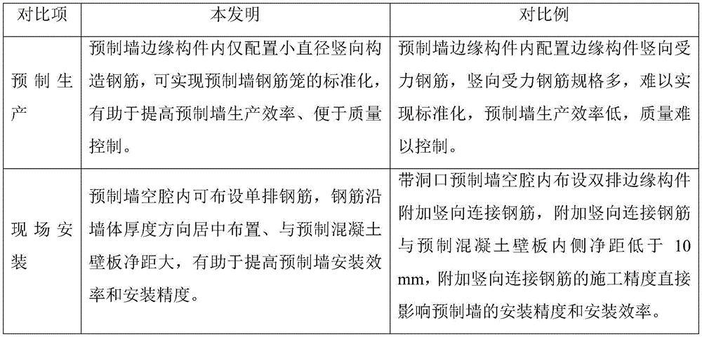
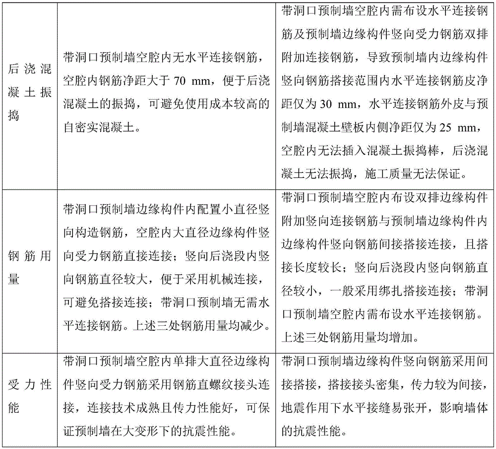
综上,本发明公开了一种带洞口叠合剪力墙纵横墙侧面出筋连接节点构造, 带洞口预制墙的预制边缘构件箍筋采用组合箍筋,组合箍筋的开口箍筋弯折后 经预制墙空腔伸入与预制墙相连的竖向后浇段,借助开口箍筋实现纵横墙连接 节点位置带洞口预制墙与竖向后浇段的连接。本发明带洞口预制墙空腔内无需 布设专门水平连接钢筋,可避免现有构造中水平连接钢筋与带洞口预制墙空腔 内边缘构件竖向钢筋附加连接钢筋相互干扰的问题,可保证带洞口预制墙边缘 构件位置空腔内后浇混凝土浇筑时的振捣空间;同时借助空腔实现侧面出筋可 避免预制墙边模开孔,有利于预制墙模具的标准化、通用化,且可避免侧面出 筋与边模的对位问题,可提高预制墙的生产效率。To sum up, the present invention discloses a structure for connecting the joints of the longitudinal and transverse walls of a superimposed shear wall with a hole. The prefabricated wall cavity extends into the vertical post-casting section connected to the prefabricated wall, and the connection between the vertical and horizontal wall connection nodes with openings and the vertical post-casting section is realized by means of opening stirrups. The invention does not need to arrange special horizontal connecting steel bars in the cavity of the prefabricated wall with holes, which can avoid the problem of mutual interference between the horizontal connecting steel bars and the additional connecting steel bars of vertical steel bars in the edge members of the prefabricated wall cavity with holes in the existing structure, and can ensure that there are holes with holes. The vibrating space for post-cast concrete pouring in the cavity of the prefabricated wall edge member; meanwhile, the side out of the cavity can avoid the opening of the prefabricated wall edge mold, which is conducive to the standardization and generalization of the prefabricated wall mold, and can avoid the side The alignment problem between the rib and the side mold can improve the production efficiency of the prefabricated wall.
以上,仅为本发明较佳的具体实施方式,但本发明的保护范围并不局限于 此,任何熟悉本技术领域的技术人员在本发明揭露的技术范围内,可轻易想到 的变化和替换,都应涵盖在本发明的保护范围之内。因此,本发明的保护范围 应该以权力要求的保护范围为准。The above are only preferred specific embodiments of the present invention, but the protection scope of the present invention is not limited thereto. Any person skilled in the art can easily think of changes and substitutions within the technical scope disclosed by the present invention, All should be included within the protection scope of the present invention. Therefore, the protection scope of the present invention should be subject to the protection scope of the claims.
Claims (10)
Priority Applications (1)
| Application Number | Priority Date | Filing Date | Title |
|---|---|---|---|
| CN202010537586.0A CN111851787B (en) | 2020-06-12 | 2020-06-12 | A joint structure for connecting vertical and horizontal walls of a composite shear wall with openings and reinforcement |
Applications Claiming Priority (1)
| Application Number | Priority Date | Filing Date | Title |
|---|---|---|---|
| CN202010537586.0A CN111851787B (en) | 2020-06-12 | 2020-06-12 | A joint structure for connecting vertical and horizontal walls of a composite shear wall with openings and reinforcement |
Publications (2)
| Publication Number | Publication Date |
|---|---|
| CN111851787A true CN111851787A (en) | 2020-10-30 |
| CN111851787B CN111851787B (en) | 2025-08-26 |
Family
ID=72987910
Family Applications (1)
| Application Number | Title | Priority Date | Filing Date |
|---|---|---|---|
| CN202010537586.0A Active CN111851787B (en) | 2020-06-12 | 2020-06-12 | A joint structure for connecting vertical and horizontal walls of a composite shear wall with openings and reinforcement |
Country Status (1)
| Country | Link |
|---|---|
| CN (1) | CN111851787B (en) |
Cited By (1)
| Publication number | Priority date | Publication date | Assignee | Title |
|---|---|---|---|---|
| CN112376801A (en) * | 2020-12-04 | 2021-02-19 | 中国建筑标准设计研究院有限公司 | Coincide shear wall edge member of high-efficient configuration vertical reinforcement |
Citations (10)
| Publication number | Priority date | Publication date | Assignee | Title |
|---|---|---|---|---|
| JPH06306977A (en) * | 1993-04-22 | 1994-11-01 | Shimizu Corp | Precast wall formwork, earthquake-resistant wall using it, and its construction method |
| CN104652654A (en) * | 2015-02-11 | 2015-05-27 | 沈阳建筑大学 | Novel assembled shear wall structure |
| CN108049504A (en) * | 2017-12-19 | 2018-05-18 | 浙江绿筑集成科技有限公司 | A kind of assembled faced wall connection method |
| CN109537773A (en) * | 2017-09-22 | 2019-03-29 | 天津远大兴辰住宅工业有限公司 | Connection structure at vertical abutment joint at prefabricated concrete structure L shape shear wall |
| CN109868918A (en) * | 2019-02-26 | 2019-06-11 | 武汉理工大学 | A kind of connecting structure of L shape overlapped shear wall edge member |
| CN110700419A (en) * | 2019-09-16 | 2020-01-17 | 锦萧建筑科技有限公司 | Novel integrated connecting structure for quickly assembling membrane shell wall and hidden column |
| CN111119378A (en) * | 2020-01-14 | 2020-05-08 | 韩静 | Prefabricated hollow superposed shear wall with vertical steel bars penetrating through edge members |
| CN111119398A (en) * | 2020-01-14 | 2020-05-08 | 净小平 | Prefabricated hollow superposed shear wall based on flat die production and steel bar lapping |
| CN111119377A (en) * | 2020-01-14 | 2020-05-08 | 韩静 | Prefabricated Hollow Laminated Shear Wall with Vertical Reinforcement Out of Reinforcement and Shaped Pipe Holes |
| CN212562032U (en) * | 2020-06-12 | 2021-02-19 | 中国建筑标准设计研究院有限公司 | Take entrance to a cave superimposed shear wall to go out muscle connected node structure in side of indulging and violently wall |
-
2020
- 2020-06-12 CN CN202010537586.0A patent/CN111851787B/en active Active
Patent Citations (10)
| Publication number | Priority date | Publication date | Assignee | Title |
|---|---|---|---|---|
| JPH06306977A (en) * | 1993-04-22 | 1994-11-01 | Shimizu Corp | Precast wall formwork, earthquake-resistant wall using it, and its construction method |
| CN104652654A (en) * | 2015-02-11 | 2015-05-27 | 沈阳建筑大学 | Novel assembled shear wall structure |
| CN109537773A (en) * | 2017-09-22 | 2019-03-29 | 天津远大兴辰住宅工业有限公司 | Connection structure at vertical abutment joint at prefabricated concrete structure L shape shear wall |
| CN108049504A (en) * | 2017-12-19 | 2018-05-18 | 浙江绿筑集成科技有限公司 | A kind of assembled faced wall connection method |
| CN109868918A (en) * | 2019-02-26 | 2019-06-11 | 武汉理工大学 | A kind of connecting structure of L shape overlapped shear wall edge member |
| CN110700419A (en) * | 2019-09-16 | 2020-01-17 | 锦萧建筑科技有限公司 | Novel integrated connecting structure for quickly assembling membrane shell wall and hidden column |
| CN111119378A (en) * | 2020-01-14 | 2020-05-08 | 韩静 | Prefabricated hollow superposed shear wall with vertical steel bars penetrating through edge members |
| CN111119398A (en) * | 2020-01-14 | 2020-05-08 | 净小平 | Prefabricated hollow superposed shear wall based on flat die production and steel bar lapping |
| CN111119377A (en) * | 2020-01-14 | 2020-05-08 | 韩静 | Prefabricated Hollow Laminated Shear Wall with Vertical Reinforcement Out of Reinforcement and Shaped Pipe Holes |
| CN212562032U (en) * | 2020-06-12 | 2021-02-19 | 中国建筑标准设计研究院有限公司 | Take entrance to a cave superimposed shear wall to go out muscle connected node structure in side of indulging and violently wall |
Cited By (1)
| Publication number | Priority date | Publication date | Assignee | Title |
|---|---|---|---|---|
| CN112376801A (en) * | 2020-12-04 | 2021-02-19 | 中国建筑标准设计研究院有限公司 | Coincide shear wall edge member of high-efficient configuration vertical reinforcement |
Also Published As
| Publication number | Publication date |
|---|---|
| CN111851787B (en) | 2025-08-26 |
Similar Documents
| Publication | Publication Date | Title |
|---|---|---|
| CN105569224B (en) | Concrete filled steel tube edge constraint overlaps monoblock type shear wall and preparation and installation method | |
| CN207878747U (en) | A kind of laminated floor slab prefabricated board | |
| CN111691581A (en) | On-site formwork-free longitudinal and transverse wall connecting structure for superposed shear wall and construction process | |
| CN105256891A (en) | Prefabricated concrete frame structure with high-strength bottom bars | |
| CN105822000A (en) | Steel plate and concrete composite beam and slab structure system | |
| CN106522552B (en) | A kind of assembled plate-column structure floor and its division methods and floor panels component | |
| CN102418425B (en) | Prefabrication integral casting building structure system with cast-in-site haunched beams, and construction method for prefabrication integral casting building structure system | |
| CN101503892B (en) | Connection nodes between steel reinforced concrete full prefabricated assembly structural shear wall and beam | |
| CN114482400A (en) | Superposed beam connected with prefabricated vertical component | |
| CN101503888B (en) | Interlayer connection node between outer shear wall, plate and shear walls | |
| CN112695914B (en) | Assembly type shear wall structure system and construction method thereof | |
| CN111691580A (en) | Superposed embedded column with large-diameter edge member vertical stress reinforcing steel bars arranged in cavity and prefabricated wall | |
| CN101435233A (en) | Steel tube concrete - punching steel plate - concrete combined shear wall and manufacturing method thereof | |
| CN104929294A (en) | Concrete composite plate with built-in cross hollow square steel pipes | |
| CN111691601A (en) | Overlapped column with corner vertical holes in centralized arrangement and directly connected with stressed longitudinal bars and construction process | |
| CN105569222A (en) | Vertical connection technology for precast assembled large panel shear walls with concealed supports | |
| CN111691583B (en) | A composite shear wall vertical and horizontal wall connection node structure with concentrated reinforcement in vertical post-cast sections | |
| CN201395870Y (en) | Connection node between reinforced concrete fully pre-fabricated assembly structural shear wall and beam | |
| CN212562032U (en) | Take entrance to a cave superimposed shear wall to go out muscle connected node structure in side of indulging and violently wall | |
| CN102704597A (en) | Encased concrete composite shear wall embedded with dense steel plate beams between concrete-filled steel tube columns and construction method thereof | |
| CN108086535A (en) | A kind of assembled square steel tube steel plate concrete combined shear wall | |
| CN212562033U (en) | Superposed embedded column with large-diameter vertical stress reinforcing steel bars arranged in cavity and prefabricated wall | |
| CN103924741B (en) | Band cross constraint batten plate box-shaped reinforcing bar confined concrete models and the practice | |
| CN111691579B (en) | Reinforced horizontal joint structure capable of inhibiting concentrated opening of horizontal joints of superimposed shear wall | |
| CN201395859Y (en) | Connection node between inner shear wall and plate and shear wall layer |
Legal Events
| Date | Code | Title | Description |
|---|---|---|---|
| PB01 | Publication | ||
| PB01 | Publication | ||
| SE01 | Entry into force of request for substantive examination | ||
| SE01 | Entry into force of request for substantive examination | ||
| GR01 | Patent grant | ||
| GR01 | Patent grant |