CN111849641A - A kind of plant essential oil preparation process - Google Patents
A kind of plant essential oil preparation process Download PDFInfo
- Publication number
- CN111849641A CN111849641A CN202010708134.4A CN202010708134A CN111849641A CN 111849641 A CN111849641 A CN 111849641A CN 202010708134 A CN202010708134 A CN 202010708134A CN 111849641 A CN111849641 A CN 111849641A
- Authority
- CN
- China
- Prior art keywords
- essential oil
- pipe
- steam
- tank
- condensation
- Prior art date
- Legal status (The legal status is an assumption and is not a legal conclusion. Google has not performed a legal analysis and makes no representation as to the accuracy of the status listed.)
- Withdrawn
Links
Images




Classifications
-
- C—CHEMISTRY; METALLURGY
- C11—ANIMAL OR VEGETABLE OILS, FATS, FATTY SUBSTANCES OR WAXES; FATTY ACIDS THEREFROM; DETERGENTS; CANDLES
- C11B—PRODUCING, e.g. BY PRESSING RAW MATERIALS OR BY EXTRACTION FROM WASTE MATERIALS, REFINING OR PRESERVING FATS, FATTY SUBSTANCES, e.g. LANOLIN, FATTY OILS OR WAXES; ESSENTIAL OILS; PERFUMES
- C11B9/00—Essential oils; Perfumes
- C11B9/02—Recovery or refining of essential oils from raw materials
- C11B9/022—Refining
-
- C—CHEMISTRY; METALLURGY
- C11—ANIMAL OR VEGETABLE OILS, FATS, FATTY SUBSTANCES OR WAXES; FATTY ACIDS THEREFROM; DETERGENTS; CANDLES
- C11B—PRODUCING, e.g. BY PRESSING RAW MATERIALS OR BY EXTRACTION FROM WASTE MATERIALS, REFINING OR PRESERVING FATS, FATTY SUBSTANCES, e.g. LANOLIN, FATTY OILS OR WAXES; ESSENTIAL OILS; PERFUMES
- C11B9/00—Essential oils; Perfumes
- C11B9/02—Recovery or refining of essential oils from raw materials
- C11B9/025—Recovery by solvent extraction
-
- C—CHEMISTRY; METALLURGY
- C11—ANIMAL OR VEGETABLE OILS, FATS, FATTY SUBSTANCES OR WAXES; FATTY ACIDS THEREFROM; DETERGENTS; CANDLES
- C11B—PRODUCING, e.g. BY PRESSING RAW MATERIALS OR BY EXTRACTION FROM WASTE MATERIALS, REFINING OR PRESERVING FATS, FATTY SUBSTANCES, e.g. LANOLIN, FATTY OILS OR WAXES; ESSENTIAL OILS; PERFUMES
- C11B9/00—Essential oils; Perfumes
- C11B9/02—Recovery or refining of essential oils from raw materials
- C11B9/027—Recovery of volatiles by distillation or stripping
Landscapes
- Chemical & Material Sciences (AREA)
- Life Sciences & Earth Sciences (AREA)
- Engineering & Computer Science (AREA)
- Chemical Kinetics & Catalysis (AREA)
- Oil, Petroleum & Natural Gas (AREA)
- Wood Science & Technology (AREA)
- Organic Chemistry (AREA)
- Vaporization, Distillation, Condensation, Sublimation, And Cold Traps (AREA)
Abstract
Description
技术领域technical field
本发明涉及植物精油制备技术领域,具体说是一种植物精油制备工艺。The invention relates to the technical field of plant essential oil preparation, in particular to a process for preparing plant essential oil.
背景技术Background technique
植物精油是萃取植物特有的芳香物质,取自于草本植物的花、叶、根、树皮、果实、种子、树脂等以蒸馏、压榨方式提炼出来的。水蒸汽蒸溜法是植物精油提取的一种常用方法,其原理是,芳香植物置于蒸馏容器内,再将高温的蒸汽通入其中,此时植物体内包含芳香成分的精油就会扩散到水蒸气中,形成油与水的共沸物,其后,将共沸物冷却,由于油不溶于水,从而便与水分离而形成了我们所需要的精油,水蒸汽蒸馏法非常方便,而且不必使用化学溶剂,所以现在的应用仍然很普遍。现有的制备装置在进行使用时,物料堆积在蒸馏罐的内部,产生堆积,使得物料内包含芳香成分的精油就不能够扩散到水蒸气中,使得生产效率和生产效果较差,并且由于冷凝机构的不完全冷凝,会导致排出装置的气体中含有精油气体,使得精油制备的产量降低。Plant essential oils are extracted from the unique aromatic substances of plants, which are extracted from the flowers, leaves, roots, bark, fruits, seeds, resins, etc. of herbs by distillation and pressing. The steam distillation method is a common method for the extraction of plant essential oils. In the process, an azeotrope of oil and water is formed. After that, the azeotrope is cooled. Since the oil is insoluble in water, it is separated from the water to form the essential oil we need. The steam distillation method is very convenient and does not have to be used. chemical solvent, so the application is still very common now. When the existing preparation device is used, the materials are accumulated inside the distillation tank, resulting in accumulation, so that the essential oil containing the aromatic components in the materials cannot be diffused into the water vapor, so that the production efficiency and production effect are poor, and due to condensation. Incomplete condensation of the mechanism will cause the gas discharged from the device to contain essential oil gas, which reduces the yield of essential oil preparation.
发明内容SUMMARY OF THE INVENTION
针对现有技术中的问题,本发明提供了一种植物精油制备工艺。In view of the problems in the prior art, the present invention provides a process for preparing plant essential oil.
本发明解决其技术问题所采用的技术方案是:一种植物精油制备工艺,该工艺包括以下步骤:The technical scheme adopted by the present invention to solve the technical problem is: a process for preparing plant essential oil, which comprises the following steps:
S1:选取新鲜的植物原料,将其洗净烘干水分,并将植物原料粉碎,再次对其进行打浆处理,使得打浆处理之后的植物原料烘干成粉末状;S1: select fresh plant raw material, wash and dry it for moisture, pulverize the plant raw material, and perform beating treatment on it again, so that the plant raw material after the beating treatment is dried into powder;
S2:将S1中的粉末状植物原料投入到制备设备中,并向其中添加适量的的水溶液,然后,采用热水浴对其进行升温加热,并向其中加入适量的混合酶,边搅拌边加热,使得获取混合液进行固液分离,获得粗提取液;S2: put the powdered plant raw materials in S1 into the preparation equipment, add an appropriate amount of aqueous solution to it, then use a hot water bath to heat it up, add an appropriate amount of mixed enzymes to it, and heat while stirring , so that the obtained mixed solution is subjected to solid-liquid separation to obtain a crude extract;
S3:将S2中获取的粗提取液放入到超声设备中超声一段时间后,加入适量的有机萃取剂,采用分液漏斗萃取器振荡混匀,静置一段时间后分离出植物油分,并回收有机萃取剂;S3: Put the crude extract obtained in S2 into ultrasonic equipment for a period of time, add an appropriate amount of organic extractant, use a separatory funnel extractor to oscillate and mix, and leave for a period of time to separate the vegetable oil and recover it. organic extractant;
S2中的制备设备包括蒸汽机构、蒸馏机构、冷凝机构和暂存机构,所述蒸汽机构设置在蒸馏机构的一侧,所述蒸馏机构远离蒸汽机构的一侧设置有冷凝机构,所述冷凝机构远离蒸馏机构的一侧设置有暂存机构;所述蒸馏机构与所述冷凝机构之间安装有传动机构,其中,所述传动机构包括偏心轮、连杆和活塞,所述偏心轮安装在所述蒸馏机构的输出轴上,且所述偏心轮连接连杆,且所述连杆的一端连接活塞。The preparation equipment in S2 includes a steam mechanism, a distillation mechanism, a condensation mechanism and a temporary storage mechanism. The steam mechanism is provided on one side of the distillation mechanism, and a condensation mechanism is provided on the side of the distillation mechanism away from the steam mechanism. The condensation mechanism A temporary storage mechanism is provided on the side away from the distillation mechanism; a transmission mechanism is installed between the distillation mechanism and the condensation mechanism, wherein the transmission mechanism includes an eccentric wheel, a connecting rod and a piston, and the eccentric wheel is installed in the on the output shaft of the distillation mechanism, and the eccentric is connected to a connecting rod, and one end of the connecting rod is connected to a piston.
具体的,所述蒸汽机构由蒸汽罐、固定机架、第一伺服电机、第一联轴器、第一转动轴、蒸汽排叶、清水搅拌叶、进水管和蒸汽排管组成,所述蒸汽罐的顶部通过固定机架固定连接有第一伺服电机,所述第一伺服电机输出轴的轴壁上通过第一联轴器固定连接有第一转动轴,所述第一转动轴远离第一伺服电机的一端穿过蒸汽罐,所述第一转动轴与蒸汽罐转动连接,所述第一转动轴延伸至蒸汽罐内部一端的轴壁上固定连接有蒸汽排叶和清水搅拌叶,所述蒸汽排叶设置在清水搅拌叶的上方,所述蒸汽罐的顶部固定连通有进水管和蒸汽排管,所述进水管设置在蒸汽排管远离蒸馏机构的一侧,且所述进水管的管壁上设置有闸阀。Specifically, the steam mechanism is composed of a steam tank, a fixed frame, a first servo motor, a first coupling, a first rotating shaft, a steam exhaust blade, a clean water stirring blade, a water inlet pipe and a steam exhaust pipe. The top of the tank is fixedly connected with a first servo motor through a fixed frame, and the shaft wall of the output shaft of the first servo motor is fixedly connected with a first rotating shaft through a first coupling, and the first rotating shaft is far away from the first rotating shaft. One end of the servo motor passes through the steam tank, the first rotating shaft is rotatably connected with the steam tank, and the first rotating shaft extends to the inner end of the steam tank. A shaft wall at one end is fixedly connected with a steam exhaust blade and a clean water stirring blade. The steam exhaust blade is arranged above the clear water stirring blade, the top of the steam tank is fixedly connected with a water inlet pipe and a steam exhaust pipe, the water inlet pipe is arranged on the side of the steam exhaust pipe away from the distillation mechanism, and the pipe of the water inlet pipe A gate valve is arranged on the wall.
具体的,所述蒸馏机构由外罐体、罐盖、排气管、蒸汽进管、内罐体、第二伺服电机、输出轴、第二转动轴、搅拌杆、腾料杆和导气通孔组成,所述罐盖设置在外罐体的上方,且所述罐盖螺纹套接在外罐体顶部的外罐壁上,所述罐盖的顶部固定连通有排气管,所述外罐体的底部固定连通有蒸汽进管,所述蒸汽进管的另一端与蒸汽排管连通,所述外罐体的内部设置有内罐体,所述内罐体的外壁上开设有若干个导气通孔,所述外罐体远离蒸汽机构一侧的外壁上通过固定机架固定连接有第二伺服电机,所述第二伺服电机输出轴的轴壁上通过输出轴固定连接有第二转动轴,所述第二转动轴远离第二伺服电机的一端穿过外罐体和内罐体的侧壁,所述第二转动轴与外罐体和内罐体转动连接,所述第二转动轴延伸至内罐体内部一端的轴壁上固定连接有搅拌杆,所述搅拌杆的另一端固定连接腾料杆。Specifically, the distillation mechanism consists of an outer tank body, a tank cover, an exhaust pipe, a steam inlet pipe, an inner tank body, a second servo motor, an output shaft, a second rotating shaft, a stirring rod, a feeding rod and an air guide. The tank cover is arranged above the outer tank body, and the tank cover is threadedly sleeved on the outer tank wall on the top of the outer tank body. The top of the tank cover is fixedly connected with an exhaust pipe, and the outer tank body The bottom of the tank is fixedly connected with a steam inlet pipe, the other end of the steam inlet pipe is communicated with the steam exhaust pipe, an inner tank body is arranged inside the outer tank body, and a number of air guides are opened on the outer wall of the inner tank body. a through hole, a second servo motor is fixedly connected to the outer wall of the outer tank away from the steam mechanism through a fixed frame, and a second rotating shaft is fixedly connected to the shaft wall of the output shaft of the second servo motor through the output shaft , the end of the second rotation shaft away from the second servo motor passes through the side walls of the outer tank body and the inner tank body, the second rotation shaft is rotatably connected with the outer tank body and the inner tank body, and the second rotation axis A stirring rod is fixedly connected to the shaft wall extending to one end of the inner tank body, and the other end of the stirring rod is fixedly connected to the feeding rod.
具体的,所述冷凝机构由冷凝罐、节状式球形冷凝管、冷水管、水泵、回流管、热水管和精油排管组成,所述节状式球形冷凝管设置在冷凝罐的内部,所述冷凝罐的底部固定连通有冷水管,所述冷水管的另一端与水泵的输出端连接,所述冷凝罐的顶部固定连通有回流管和热水管,所述回流管设置在热水管靠近蒸馏机构的一侧,且所述回流管远离冷凝罐的一端与进水管连接,所述热水管的管壁上设置有闸阀,所述节状式球形冷凝管的一端与排气管连接,所述节状式球形冷凝管的另一端连接有精油排管,所述精油排管的另一端穿过冷凝罐。Specifically, the condensing mechanism is composed of a condensing tank, a nodular spherical condensing pipe, a cold water pipe, a water pump, a return pipe, a hot water pipe and an essential oil drain pipe, and the nodular spherical condensing pipe is arranged inside the condensing tank, The bottom of the condensation tank is fixedly connected with a cold water pipe, the other end of the cold water pipe is connected with the output end of the water pump, the top of the condensation tank is fixedly connected with a return pipe and a hot water pipe, and the return pipe is arranged in the hot water. The pipe is close to the side of the distillation mechanism, and the end of the return pipe away from the condensation tank is connected with the water inlet pipe, the pipe wall of the hot water pipe is provided with a gate valve, and one end of the nodular spherical condenser pipe is connected to the exhaust pipe. connection, the other end of the nodular spherical condenser pipe is connected with an essential oil drain pipe, and the other end of the essential oil drain pipe passes through the condensation tank.
具体的,所述暂存机构由精油暂存罐和混合液气体罐组成,所述精油暂存罐固定连通在精油排管底部的管壁上,且所述精油暂存罐设置在混合液气体罐靠近冷凝机构的一侧,所述精油排管远离冷凝罐的一端延伸至混合液气体罐的内底部。Specifically, the temporary storage mechanism is composed of an essential oil temporary storage tank and a mixed liquid gas tank, the essential oil temporary storage tank is fixedly connected to the pipe wall at the bottom of the essential oil pipe, and the essential oil temporary storage tank is arranged in the mixed liquid gas The tank is close to the side of the condensation mechanism, and the end of the essential oil drain pipe away from the condensation tank extends to the inner bottom of the mixed liquid gas tank.
具体的,所述固定机架由固定箍、固定杆、固定板和沉头螺栓组成,所述固定箍固定套接在伺服电机上,所述固定箍一侧的侧壁上固定连接有两个固定杆,两个所述固定杆分别固定连接在固定箍的两端,所述固定杆远离固定箍的一端固定连接有固定板,所述固定板上设置有沉头螺栓。Specifically, the fixing frame is composed of a fixing hoop, a fixing rod, a fixing plate and a countersunk head bolt, the fixing hoop is fixedly sleeved on the servo motor, and two side walls are fixedly connected to the side wall of the fixing hoop. A fixing rod, the two fixing rods are respectively fixedly connected to the two ends of the fixing hoop, and one end of the fixing rods away from the fixing hoop is fixedly connected with a fixing plate, and the fixing plate is provided with a countersunk head bolt.
具体的,所述精油排管位于精油暂存罐和混合液气体罐之间的管体呈凸状结构,且所述混合液气体罐内部设置有非极性溶剂。Specifically, the pipe body of the essential oil drain pipe located between the essential oil temporary storage tank and the mixed liquid gas tank has a convex structure, and the mixed liquid gas tank is provided with a non-polar solvent.
本发明的有益效果:Beneficial effects of the present invention:
(1)本发明所述的一种植物精油制备工艺,通过蒸馏机构内的伺服电机能够带动搅拌杆和腾料杆对内罐体中的物料进行翻转,物料不会堆积,使得物料内包含芳香成分的精油能够充分的扩散到水蒸气中,物料受热均匀,使得生产效率提高。(1) The preparation process of a kind of plant essential oil according to the present invention, the servo motor in the distillation mechanism can drive the stirring rod and the feeding rod to overturn the material in the inner tank, and the material will not accumulate, so that the material contains aroma The essential oil of the ingredients can be fully diffused into the water vapor, and the material is heated evenly, which improves the production efficiency.
(2)本发明所述的一种植物精油制备工艺,通过暂存机构内的精油暂存罐能够有效的对精油排管排出的精油液体进行收集,设置的混合液气体罐能够对未完全冷凝气体中的精油进行收集,使得精油制备的产量提高。(2) a kind of plant essential oil preparation process of the present invention, the essential oil liquid discharged from the essential oil pipe can be effectively collected by the essential oil temporary storage tank in the temporary storage mechanism, and the mixed liquid gas tank provided can effectively condense the liquid that is not completely condensed The essential oil in the gas is collected, so that the yield of the essential oil preparation is increased.
附图说明Description of drawings
下面结合附图和实施例对本发明进一步说明。The present invention will be further described below with reference to the accompanying drawings and embodiments.
图1为本发明的工艺流程图;Fig. 1 is the process flow diagram of the present invention;
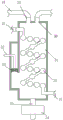
图2为本发明提供的一种植物精油制备设备的结构示意图;Fig. 2 is the structural representation of a kind of plant essential oil preparation equipment provided by the present invention;
图3为本发明提供的一种植物精油制备设备中蒸汽机构的结构示意图;Fig. 3 is the structural representation of steam mechanism in a kind of plant essential oil preparation equipment provided by the present invention;
图4为本发明提供的一种植物精油制备设备中蒸馏机构的结构示意图;Fig. 4 is the structural representation of distillation mechanism in a kind of plant essential oil preparation equipment provided by the present invention;
图5为本发明提供的一种植物精油制备设备中冷凝机构的结构示意图;5 is a schematic structural diagram of a condensation mechanism in a plant essential oil preparation equipment provided by the present invention;
图6为本发明提供的一种植物精油制备设备中暂存机构的结构示意图;6 is a schematic structural diagram of a temporary storage mechanism in a plant essential oil preparation equipment provided by the present invention;
图7为本发明提供的一种植物精油制备设备中固定机架的结构示意图。7 is a schematic structural diagram of a fixed rack in a plant essential oil preparation equipment provided by the present invention.
图中:1、蒸汽机构;11、蒸汽罐;12、固定机架;13、第一伺服电机;14、第一联轴器;15、第一转动轴;16、蒸汽排叶;17、清水搅拌叶;18、进水管;19、蒸汽排管;2、蒸馏机构;21、外罐体;22、罐盖;23、排气管;24、蒸汽进管;25、内罐体;26、第二伺服电机;27、输出轴;28、第二转动轴;29、搅拌杆;210、腾料杆;211、导气通孔;3、冷凝机构;31、冷凝罐;32、节状式球形冷凝管;33、冷水管;34、水泵;35、回流管;36、热水管;37、精油排管;4、暂存机构;41、精油暂存罐;42、混合液气体罐;121、固定箍;122、固定杆;123、固定板;124、沉头螺栓,5、传动机构,51、偏心轮,52、连杆,53、活塞。In the figure: 1, steam mechanism; 11, steam tank; 12, fixed frame; 13, first servo motor; 14, first coupling; 15, first rotating shaft; 16, steam vane; 17, clean water Stirring blade; 18, water inlet pipe; 19, steam exhaust pipe; 2, distillation mechanism; 21, outer tank body; 22, tank cover; 23, exhaust pipe; 24, steam inlet pipe; 25, inner tank body; 26, The second servo motor; 27, the output shaft; 28, the second rotating shaft; 29, the stirring rod; 210, the feeding rod; 211, the air guide hole; 3, the condensation mechanism; 31, the condensation tank; Spherical condenser pipe; 33, cold water pipe; 34, water pump; 35, return pipe; 36, hot water pipe; 37, essential oil drain pipe; 4, temporary storage mechanism; 41, essential oil temporary storage tank; 42, mixed liquid gas tank; 121, fixed hoop; 122, fixed rod; 123, fixed plate; 124, countersunk head bolt, 5, transmission mechanism, 51, eccentric, 52, connecting rod, 53, piston.
具体实施方式Detailed ways
为了使本发明实现的技术手段、创作特征、达成目的与功效易于明白了解,下面结合具体实施方式,进一步阐述本发明。In order to make it easy to understand the technical means, creation features, achieved goals and effects of the present invention, the present invention will be further described below with reference to the specific embodiments.
如图1-图7所示,本发明所述的一种植物精油制备工艺,该工艺包括以下步骤:As shown in Fig. 1-Fig. 7, a kind of plant essential oil preparation technology of the present invention, this technology comprises the following steps:
S1:选取新鲜的植物原料,将其洗净烘干水分,并将植物原料粉碎,再次对其进行打浆处理,使得打浆处理之后的植物原料烘干成粉末状;S1: select fresh plant raw material, wash and dry it for moisture, pulverize the plant raw material, and perform beating treatment on it again, so that the plant raw material after the beating treatment is dried into powder;
S2:将S1中的粉末状植物原料投入到制备设备中,并向其中添加适量的的水溶液,然后,采用热水浴对其进行升温加热,并向其中加入适量的混合酶,边搅拌边加热,使得获取混合液进行固液分离,获得粗提取液;S2: put the powdered plant raw materials in S1 into the preparation equipment, add an appropriate amount of aqueous solution to it, then use a hot water bath to heat it up, add an appropriate amount of mixed enzymes to it, and heat while stirring , so that the obtained mixed solution is subjected to solid-liquid separation to obtain a crude extract;
S3:将S2中获取的粗提取液放入到超声设备中超声一段时间后,加入适量的有机萃取剂,采用分液漏斗萃取器振荡混匀,静置一段时间后分离出植物油分,并回收有机萃取剂;S3: Put the crude extract obtained in S2 into ultrasonic equipment for a period of time, add an appropriate amount of organic extractant, use a separatory funnel extractor to oscillate and mix, and leave for a period of time to separate the vegetable oil and recover it. organic extractant;
S2中的制备设备包括蒸汽机构1、蒸馏机构2、冷凝机构3和暂存机构4,所述蒸汽机构1设置在蒸馏机构2的一侧,所述蒸馏机构2远离蒸汽机构1的一侧设置有冷凝机构3,所述冷凝机构3远离蒸馏机构2的一侧设置有暂存机构4;所述蒸馏机构2与所述冷凝机构3之间安装有传动机构5,其中,所述传动机构5包括偏心轮51、连杆52和活塞53,所述偏心轮51安装在所述蒸馏机构2的输出轴27上,且所述偏心轮51连接连杆52,且所述连杆52的一端连接活塞53,通过输出轴27的转动带动偏心轮51的转动,通过偏心轮51的转动实现连杆52间歇性上下运动,带动活塞53上下运动,促进冷凝机构3内部液体的流动。The preparation equipment in S2 includes a
具体的,所述蒸汽机构1由蒸汽罐11、固定机架12、第一伺服电机13、第一联轴器14、第一转动轴15、蒸汽排叶16、清水搅拌叶17、进水管18和蒸汽排管19组成,所述蒸汽罐11的顶部通过固定机架12固定连接有第一伺服电机13,所述第一伺服电机13输出轴的轴壁上通过第一联轴器14固定连接有第一转动轴15,所述第一转动轴15远离第一伺服电机13的一端穿过蒸汽罐11,所述第一转动轴15与蒸汽罐11转动连接,所述第一转动轴15延伸至蒸汽罐11内部一端的轴壁上固定连接有蒸汽排叶16和清水搅拌叶17,所述蒸汽排叶16设置在清水搅拌叶17的上方,所述蒸汽罐11的顶部固定连通有进水管18和蒸汽排管19,所述进水管18设置在蒸汽排管19远离蒸馏机构2的一侧,且所述进水管18的管壁上设置有闸阀,能够快速高效的生产高温水蒸气。Specifically, the
具体的,所述蒸馏机构2由外罐体21、罐盖22、排气管23、蒸汽进管24、内罐体25、第二伺服电机26、输出轴27、第二转动轴28、搅拌杆29、腾料杆210和导气通孔211组成,所述罐盖22设置在外罐体21的上方,且所述罐盖22螺纹套接在外罐体21顶部的外罐壁上,所述罐盖22的顶部固定连通有排气管23,所述外罐体21的底部固定连通有蒸汽进管24,所述蒸汽进管24的另一端与蒸汽排管19连通,所述外罐体21的内部设置有内罐体25,所述内罐体25的外壁上开设有若干个导气通孔211,所述外罐体21远离蒸汽机构1一侧的外壁上通过固定机架12固定连接有第二伺服电机26,所述第二伺服电机26输出轴的轴壁上通过输出轴27固定连接有第二转动轴28,所述第二转动轴28远离第二伺服电机26的一端穿过外罐体21和内罐体25的侧壁,所述第二转动轴28与外罐体21和内罐体25转动连接,所述第二转动轴28延伸至内罐体25内部一端的轴壁上固定连接有搅拌杆29,所述搅拌杆29的另一端固定连接腾料杆210,能够对物料进行搅拌,使得物料受热均与,不会产生堆积。Specifically, the
具体的,所述冷凝机构3由冷凝罐31、节状式球形冷凝管32、冷水管33、水泵34、回流管35、热水管36和精油排管37组成,所述节状式球形冷凝管32设置在冷凝罐31的内部,所述冷凝罐31的底部固定连通有冷水管33,所述冷水管33的另一端与水泵34的输出端连接,所述冷凝罐31的顶部固定连通有回流管35和热水管36,所述回流管35设置在热水管36靠近蒸馏机构2的一侧,且所述回流管35远离冷凝罐31的一端与进水管18连接,所述热水管36的管壁上设置有闸阀,所述节状式球形冷凝管32的一端与排气管23连接,所述节状式球形冷凝管32的另一端连接有精油排管37,所述精油排管37的另一端穿过冷凝罐31,能够快速的对混合蒸汽进行冷凝,并且通过设置的回流管35能将热水回流至蒸汽罐11的内部,节约资源。Specifically, the condensation mechanism 3 is composed of a
具体的,所述暂存机构4由精油暂存罐41和混合液气体罐42组成,所述精油暂存罐41固定连通在精油排管37底部的管壁上,且所述精油暂存罐41设置在混合液气体罐42靠近冷凝机构3的一侧,所述精油排管37远离冷凝罐31的一端延伸至混合液气体罐42的内底部,能够有效的防止装置未完全将混合气体冷凝,从而可以有效的防止装置排出的气体中含有精油。Specifically, the temporary storage mechanism 4 is composed of an essential oil
具体的,所述固定机架12由固定箍121、固定杆122、固定板123和沉头螺栓124组成,所述固定箍121固定套接在伺服电机上,所述固定箍121一侧的侧壁上固定连接有两个固定杆122,两个所述固定杆122分别固定连接在固定箍121的两端,所述固定杆122远离固定箍121的一端固定连接有固定板123,所述固定板123上设置有沉头螺栓124,拆卸下沉头螺栓124即可完成固定机架12的拆卸,便于伺服电机的拆装,省时省力。Specifically, the fixing
具体的,所述精油排管37位于精油暂存罐41和混合液气体罐42之间的管体呈凸状结构,能够有效的防止冷凝后的精油排至精油暂存罐41的内部,且所述混合液气体罐42内部设置的非极性溶剂能够对混合气体中的精油进行吸附。Specifically, the pipe body of the essential
在使用时,开启进水管18上的闸阀,关闭热水管36上的闸阀,通过水泵34将清水输送至冷凝罐31的内部,冷凝罐31内部的清水通过进水管18输送至蒸汽罐11的内部,将物料放置在内罐体25的内部,旋转拧紧罐盖22,通过加热器对蒸汽罐11进行加热,通过外接电源启动第一伺服电机13驱动,第一伺服电机13带动清水搅拌叶17和蒸汽排叶16转动,清水搅拌叶17在转动时能够带动蒸汽罐11内的清水进行搅拌,使得清水受热均匀,蒸汽排叶16转动时能够加速水蒸气输送至蒸汽排管19的速度,清水在加热后产生含有大量热量的水蒸气,水蒸气由蒸汽排管19输送至外罐体21的内部,蒸汽排管19内的蒸汽由蒸汽进管24输送至外罐体21与内罐体25之间的空腔内,空腔内的水蒸气由导气通孔211均由的扩散至内罐体25的内部,对物料进行蒸馏,通过外接电源启动第二伺服电机26驱动,第二伺服电机26驱动时带动第二转动轴28转动,第二转动轴28转动时能够带动搅拌杆29和腾料杆210对内罐体25内的物料进行翻转,物料不会堆积,使得物料内包含芳香成分的精油能够充分的扩散到水蒸气中,物料受热均匀,使得生产效率提高,带有精油的混合气体和水蒸气由排气管23排至节状式球形冷凝管32的内部,冷凝罐31内的冷水对节状式球形冷凝管32内的混合气体进行冷凝,使得混合气体变为液体,液体精油滴落至精油暂存罐41的内部,当冷凝机构3未完全对气体进行冷凝时,精油排管37将未冷凝的气体输送至混合液气体罐42的内部,混合液气体罐42内部的非极性溶剂(石油醚、甲苯)能够对气体中的精油进行吸附收集,使得精油制备的产量提高。During use, the gate valve on the
以上显示和描述了本发明的基本原理、主要特征和优点。本行业的技术人员应该了解,本发明不受上述实施例的限制,上述实施方式和说明书中的描述的只是说明本发明的原理,在不脱离本发明精神和范围的前提下,本发明还会有各种变化和改进,这些变化和改进都落入本发明要求保护的范围内。本发明要求保护范围由所附的权利要求书及其等效物界定。The foregoing has shown and described the basic principles, main features and advantages of the present invention. Those skilled in the art should understand that the present invention is not limited by the above-mentioned embodiments, and the descriptions in the above-mentioned embodiments and the description are only to illustrate the principle of the present invention. Without departing from the spirit and scope of the present invention, the present invention will also There are various changes and improvements which fall within the scope of the claimed invention. The claimed scope of the present invention is defined by the appended claims and their equivalents.
Claims (7)
Priority Applications (1)
| Application Number | Priority Date | Filing Date | Title |
|---|---|---|---|
| CN202010708134.4A CN111849641A (en) | 2020-07-21 | 2020-07-21 | A kind of plant essential oil preparation process |
Applications Claiming Priority (1)
| Application Number | Priority Date | Filing Date | Title |
|---|---|---|---|
| CN202010708134.4A CN111849641A (en) | 2020-07-21 | 2020-07-21 | A kind of plant essential oil preparation process |
Publications (1)
| Publication Number | Publication Date |
|---|---|
| CN111849641A true CN111849641A (en) | 2020-10-30 |
Family
ID=73000824
Family Applications (1)
| Application Number | Title | Priority Date | Filing Date |
|---|---|---|---|
| CN202010708134.4A Withdrawn CN111849641A (en) | 2020-07-21 | 2020-07-21 | A kind of plant essential oil preparation process |
Country Status (1)
| Country | Link |
|---|---|
| CN (1) | CN111849641A (en) |
Cited By (5)
| Publication number | Priority date | Publication date | Assignee | Title |
|---|---|---|---|---|
| CN112410125A (en) * | 2020-11-23 | 2021-02-26 | 青海师范大学 | A chamomile essential oil extraction device |
| CN112662475A (en) * | 2020-12-14 | 2021-04-16 | 陈容 | Plant essential oil extraction device and method for cosmetic production |
| CN113786359A (en) * | 2021-09-22 | 2021-12-14 | 王蕾 | Perfume containing plant natural components and preparation method thereof |
| CN114774196A (en) * | 2022-03-30 | 2022-07-22 | 南京昌阳科技发展有限公司 | Distillation device for extracting plant essential oil by steam distillation method |
| CN116747554A (en) * | 2023-08-11 | 2023-09-15 | 烟台载物生物科技有限公司 | Sea cucumber peptide production extraction device |
Citations (9)
| Publication number | Priority date | Publication date | Assignee | Title |
|---|---|---|---|---|
| KR100820344B1 (en) * | 2006-10-19 | 2008-04-07 | 주식회사 파인엠 | Plant essential oil extraction |
| EP2294931A1 (en) * | 2009-09-02 | 2011-03-16 | Drom Fragrances GmbH & Co. KG | Improved process and improved apparatus for yielding plant ingredients |
| CN207581757U (en) * | 2017-10-12 | 2018-07-06 | 衢州味千生物技术有限公司 | A kind of extraction element of aromatic vegetable oil |
| CN110055131A (en) * | 2019-03-28 | 2019-07-26 | 广州白云山维一实业股份有限公司 | The production method of plants essential oil |
| CN209602489U (en) * | 2019-02-22 | 2019-11-08 | 深圳市众创美力生物科技有限公司 | A kind of Rosa Damascana extraction element |
| CN210140570U (en) * | 2019-11-15 | 2020-03-13 | 海南女人春天美容有限公司 | Plant essential oil extraction device |
| CN210620745U (en) * | 2019-08-28 | 2020-05-26 | 宁夏嘉禾花语生态农业有限公司 | Distillation extraction and oil-water separation equipment of plant essence |
| CN210736706U (en) * | 2019-10-17 | 2020-06-12 | 珠海横琴新区御峰沉香产业有限公司 | Aquilaria agallocha essential oil distillation extraction device |
| CN111349520A (en) * | 2020-03-20 | 2020-06-30 | 谭宇航 | A kind of plant essential oil distillation preparation method |
-
2020
- 2020-07-21 CN CN202010708134.4A patent/CN111849641A/en not_active Withdrawn
Patent Citations (9)
| Publication number | Priority date | Publication date | Assignee | Title |
|---|---|---|---|---|
| KR100820344B1 (en) * | 2006-10-19 | 2008-04-07 | 주식회사 파인엠 | Plant essential oil extraction |
| EP2294931A1 (en) * | 2009-09-02 | 2011-03-16 | Drom Fragrances GmbH & Co. KG | Improved process and improved apparatus for yielding plant ingredients |
| CN207581757U (en) * | 2017-10-12 | 2018-07-06 | 衢州味千生物技术有限公司 | A kind of extraction element of aromatic vegetable oil |
| CN209602489U (en) * | 2019-02-22 | 2019-11-08 | 深圳市众创美力生物科技有限公司 | A kind of Rosa Damascana extraction element |
| CN110055131A (en) * | 2019-03-28 | 2019-07-26 | 广州白云山维一实业股份有限公司 | The production method of plants essential oil |
| CN210620745U (en) * | 2019-08-28 | 2020-05-26 | 宁夏嘉禾花语生态农业有限公司 | Distillation extraction and oil-water separation equipment of plant essence |
| CN210736706U (en) * | 2019-10-17 | 2020-06-12 | 珠海横琴新区御峰沉香产业有限公司 | Aquilaria agallocha essential oil distillation extraction device |
| CN210140570U (en) * | 2019-11-15 | 2020-03-13 | 海南女人春天美容有限公司 | Plant essential oil extraction device |
| CN111349520A (en) * | 2020-03-20 | 2020-06-30 | 谭宇航 | A kind of plant essential oil distillation preparation method |
Non-Patent Citations (1)
| Title |
|---|
| 李川山等: "植物精油提取工艺研究进展", 大众科技, no. 09, pages 86 - 87 * |
Cited By (8)
| Publication number | Priority date | Publication date | Assignee | Title |
|---|---|---|---|---|
| CN112410125A (en) * | 2020-11-23 | 2021-02-26 | 青海师范大学 | A chamomile essential oil extraction device |
| CN112662475A (en) * | 2020-12-14 | 2021-04-16 | 陈容 | Plant essential oil extraction device and method for cosmetic production |
| CN112662475B (en) * | 2020-12-14 | 2023-08-25 | 杭州岛屿星晴生物技术有限公司 | Plant essential oil extraction device and extraction method for cosmetic production |
| CN113786359A (en) * | 2021-09-22 | 2021-12-14 | 王蕾 | Perfume containing plant natural components and preparation method thereof |
| CN113786359B (en) * | 2021-09-22 | 2024-03-08 | 王蕾 | Perfume containing natural plant components and preparation method thereof |
| CN114774196A (en) * | 2022-03-30 | 2022-07-22 | 南京昌阳科技发展有限公司 | Distillation device for extracting plant essential oil by steam distillation method |
| CN116747554A (en) * | 2023-08-11 | 2023-09-15 | 烟台载物生物科技有限公司 | Sea cucumber peptide production extraction device |
| CN116747554B (en) * | 2023-08-11 | 2023-11-24 | 烟台载物生物科技有限公司 | Sea cucumber peptide production extraction device |
Similar Documents
| Publication | Publication Date | Title |
|---|---|---|
| CN211536546U (en) | Extract production equipment | |
| CN211814332U (en) | Shaddock essential oil extraction equipment | |
| CN204364938U (en) | The ultrasonic centrifugal extraction of a kind of Wave wheel type full automatic, concentrated and solvent reclaimer | |
| CN202430144U (en) | D-bomeol extraction equipment suitable for field sites | |
| CN209485017U (en) | Agalloch eaglewood material negative pressure stirring and drying machine | |
| CN104138670B (en) | A kind of extraction concentration technique of hawthorn fruit total flavone | |
| CN110655991A (en) | Plant extraction of essential oil device | |
| CN211316829U (en) | Dregs of a decoction dewatering equipment | |
| CN221385552U (en) | Plant draws enrichment facility | |
| CN221846082U (en) | Extract concentration device | |
| CN215609385U (en) | A concentrating device for plant extract | |
| CN109612241B (en) | Negative pressure stirring and drying device for agilawood materials | |
| CN209974579U (en) | A drum type livestock and poultry manure dehydration fermenter | |
| CN222266163U (en) | Rosemary essential oil raw material extraction dewatering device | |
| CN220026158U (en) | Extract circulation of ginger juice active material and cook extraction element | |
| CN220026165U (en) | Distillation equipment for plant extraction | |
| CN221905780U (en) | Apple polyphenol concentration evaporator | |
| CN223439180U (en) | Organic solvent recycling device for licorice root extraction | |
| CN221981564U (en) | Traditional chinese medicine extract product enrichment facility | |
| CN221061254U (en) | Processing equipment for rhizoma polygonati nine-steaming and nine-airing | |
| CN222287871U (en) | Soil detection drying screening device | |
| CN220802016U (en) | Extraction equipment for natural plant essence | |
| CN223846463U (en) | A plant essence extraction device | |
| CN223716385U (en) | Distillation device | |
| CN219595910U (en) | Continuous extraction system of herbicide raw materials |
Legal Events
| Date | Code | Title | Description |
|---|---|---|---|
| PB01 | Publication | ||
| PB01 | Publication | ||
| SE01 | Entry into force of request for substantive examination | ||
| SE01 | Entry into force of request for substantive examination | ||
| WW01 | Invention patent application withdrawn after publication | ||
| WW01 | Invention patent application withdrawn after publication |
Application publication date: 20201030 |