CN111834783A - A series of electrical interface and its conversion compatible method and application - Google Patents
A series of electrical interface and its conversion compatible method and application Download PDFInfo
- Publication number
- CN111834783A CN111834783A CN202010797181.0A CN202010797181A CN111834783A CN 111834783 A CN111834783 A CN 111834783A CN 202010797181 A CN202010797181 A CN 202010797181A CN 111834783 A CN111834783 A CN 111834783A
- Authority
- CN
- China
- Prior art keywords
- socket
- plug
- interface
- electrical
- conductive
- Prior art date
- Legal status (The legal status is an assumption and is not a legal conclusion. Google has not performed a legal analysis and makes no representation as to the accuracy of the status listed.)
- Pending
Links
Images


Classifications
-
- H—ELECTRICITY
- H01—ELECTRIC ELEMENTS
- H01R—ELECTRICALLY-CONDUCTIVE CONNECTIONS; STRUCTURAL ASSOCIATIONS OF A PLURALITY OF MUTUALLY-INSULATED ELECTRICAL CONNECTING ELEMENTS; COUPLING DEVICES; CURRENT COLLECTORS
- H01R13/00—Details of coupling devices of the kinds covered by groups H01R12/70 or H01R24/00 - H01R33/00
- H01R13/02—Contact members
- H01R13/04—Pins or blades for co-operation with sockets
-
- H—ELECTRICITY
- H01—ELECTRIC ELEMENTS
- H01R—ELECTRICALLY-CONDUCTIVE CONNECTIONS; STRUCTURAL ASSOCIATIONS OF A PLURALITY OF MUTUALLY-INSULATED ELECTRICAL CONNECTING ELEMENTS; COUPLING DEVICES; CURRENT COLLECTORS
- H01R13/00—Details of coupling devices of the kinds covered by groups H01R12/70 or H01R24/00 - H01R33/00
- H01R13/02—Contact members
- H01R13/10—Sockets for co-operation with pins or blades
-
- H—ELECTRICITY
- H01—ELECTRIC ELEMENTS
- H01R—ELECTRICALLY-CONDUCTIVE CONNECTIONS; STRUCTURAL ASSOCIATIONS OF A PLURALITY OF MUTUALLY-INSULATED ELECTRICAL CONNECTING ELEMENTS; COUPLING DEVICES; CURRENT COLLECTORS
- H01R13/00—Details of coupling devices of the kinds covered by groups H01R12/70 or H01R24/00 - H01R33/00
- H01R13/02—Contact members
- H01R13/35—Contact members for non-simultaneous co-operation with different types of contact member, e.g. socket co-operating with either round or flat pin
-
- H—ELECTRICITY
- H02—GENERATION; CONVERSION OR DISTRIBUTION OF ELECTRIC POWER
- H02J—ELECTRIC POWER NETWORKS; CIRCUIT ARRANGEMENTS OR SYSTEMS FOR SUPPLYING OR DISTRIBUTING ELECTRIC POWER; SYSTEMS FOR STORING ELECTRIC ENERGY
- H02J7/00—Circuit arrangements for charging or discharging batteries or for supplying loads from batteries
- H02J7/70—Circuit arrangements for charging or discharging batteries or for supplying loads from batteries characterised by the mechanical construction
- H02J7/751—Circuit arrangements for charging or discharging batteries or for supplying loads from batteries characterised by the mechanical construction concerning the insertion or the connection of the batteries
Landscapes
- Engineering & Computer Science (AREA)
- Power Engineering (AREA)
- Details Of Connecting Devices For Male And Female Coupling (AREA)
Abstract
本发明提供了一种系列电性接口和其转换兼容的方法及应用,具体为一种以不同的机械结构配以相同的电性连接适配部分形成的具有不同机械连接强度的系列电性接口,和使用无电性电路的转换件仅以单纯的机械结构与接口组合实现此类系列电性接口间兼容转换的方法。本发明中系列电性接口至少为两个接口,接口的区别至少在于接口插接横截面不同,和/或接口的接插长度不同;转换件的结构上有贯通的转换插孔,转换件与接口之一进行结构组合或配合实现接口的转换兼容。使系列电性接口在接口类型上可多型选用、可兼容、在连接强度和可靠性上可满足产品组件的组合组装、接口中同时具有数字信号传输功能可作为数码接口满足电子产品对数字信号传输的需求。
The present invention provides a series of electrical interfaces and their conversion compatible methods and applications, specifically a series of electrical interfaces with different mechanical connection strengths formed by different mechanical structures and the same electrical connection adapting part. , and a method for realizing compatible conversion between such series of electrical interfaces only with a simple mechanical structure and interface combination using a converter without an electrical circuit. In the present invention, the series of electrical interfaces are at least two interfaces, and the difference between the interfaces is at least in that the cross-sections of the interfaces are different, and/or the lengths of the interfaces are different. One of the interfaces performs structural combination or cooperates to realize the conversion compatibility of the interface. The series of electrical interfaces can be selected and compatible with various types of interfaces, and can meet the combined assembly of product components in terms of connection strength and reliability. The interface also has a digital signal transmission function. It can be used as a digital interface to meet the needs of electronic products for digital signals. transmission needs.
Description
技术领域technical field
本发明涉及接口领域和数据传输接口领域、组合电器领域、移动电源领域,具体涉及一种系列电性接口和其转换兼容的方法及应用。The invention relates to the fields of interfaces, data transmission interfaces, combined electrical appliances, and mobile power supplies, in particular to a series of electrical interfaces and their conversion-compatible methods and applications.
背景技术Background technique
随着电子电器产品普及和各类数码接口运用的日益广泛,电子电器产品也趋向于互联互通和智能化的发展,相关的互通整合接口技术成为了电子电器、智能产品的必要组成。为实现产品的数字互联、系列互通、灵活组合的发展需要,产品组件间的组合连接接口在实现组件机械组合连接的同时也增加了对数字信号传输的需求。With the popularization of electronic and electrical products and the increasingly widespread use of various digital interfaces, electronic and electrical products also tend to be interconnected and intelligent. In order to realize the development needs of digital interconnection, series interconnection, and flexible combination of products, the combined connection interface between product components not only realizes the mechanical combination connection of components, but also increases the demand for digital signal transmission.
然而,各类传统的数字信号电性接口因自身机械连接强度和连接可靠性的局限,通常不能直接用作体积大、质量大或震动强的产品组件的组合组装接口,而传统的机械组装接口更互不兼容、也不具备数字信号传输能力。现有的各类数码接口的体型尺寸、连接强度、电路定义等各不相同、标准不一,各类接口间的转换方式繁琐、成本也较高,多为使用带电性电路的专用转换件,使接口的通用性较为局限,无法真正较好地实现接口的互换兼容,继而阻碍了产品的通用互换组合的发展空间。However, due to the limitations of their own mechanical connection strength and connection reliability, various traditional digital signal electrical interfaces usually cannot be directly used as combined assembly interfaces for product components with large volumes, large masses or strong vibrations, while traditional mechanical assembly interfaces It is more incompatible with each other and does not have the ability to transmit digital signals. The size, connection strength, circuit definition, etc. of various existing digital interfaces are different, and the standards are different. The conversion method between various interfaces is cumbersome and the cost is high. Most of them are special conversion parts that use electrified circuits. The versatility of the interface is relatively limited, and the interchangeability of the interface cannot be truly realized, which in turn hinders the development space of the general interchangeable combination of products.
现代电子电器产品的智能化、便捷化、模块化、整合化的发展趋势,衍生的大量产品迫切需要一种在接口的强度和可靠性上适用于组合型、模块化产品组件的组合组装、在接口功能中同时能具备数字信号传输能力、在接口类型上可多型选用的电性接口,并以更便捷的转换方法实现电性接口的兼容转换,提高通用性。With the development trend of intelligence, convenience, modularization and integration of modern electronic and electrical products, a large number of products derived from it urgently need a combination assembly that is suitable for combined and modular product components in terms of the strength and reliability of the interface. In the interface function, at the same time, it can have digital signal transmission capability, and can choose various electrical interfaces in terms of interface types, and realize the compatible conversion of electrical interfaces with a more convenient conversion method to improve the versatility.
发明内容SUMMARY OF THE INVENTION
为解决上述问题,本发明提供了一种系列电性接口和其转换兼容的方法及应用,具体为一种以不同的机械结构配以相同的电性连接适配部分形成的具有不同机械连接强度的系列电性接口,和以无电性电路的单纯机械结构转换件实现此类系列电性接口间兼容转换的方法。In order to solve the above-mentioned problems, the present invention provides a series of electrical interfaces and their conversion compatible methods and applications, specifically, a series of electrical interfaces with different mechanical connection strengths formed by matching the same electrical connection adapting part with different mechanical structures. A series of electrical interfaces, and a method for realizing the compatible conversion between such series of electrical interfaces with a purely mechanical structure converter without electrical circuits.
本发明中系列电性接口至少为两个接口,第一接口与第二接口的区别至少在于第二接口的插接横截面大于第一接口的插接横截面,或第一接口与第二接口的区别至少在于第二接口接插长度短于第一接口接插长度;In the present invention, the series of electrical interfaces are at least two interfaces. The difference between the first interface and the second interface is at least in that the insertion cross-section of the second interface is larger than the insertion cross-section of the first interface, or the first interface and the second interface. The difference is at least in that the plug length of the second interface is shorter than the plug length of the first interface;
用于第一接口和第二接口间转换的转换件为无电性电路的单纯机械结构转换件,转换件结构上有贯通的转换插孔,转换插孔的插接横截面形状适配于第一插头的插接横截面形状,转换插孔可插接第一插头。The conversion part used for the conversion between the first interface and the second interface is a simple mechanical structure conversion part with no electrical circuit, the conversion part has a through conversion jack on the structure, and the insertion cross-sectional shape of the conversion jack is adapted to the first interface. The plug cross-sectional shape of a plug, the conversion jack can be plugged into the first plug.
当第一接口与第二接口的区别至少在于第二接口的插接横截面大于第一接口的插接横截面时,将转换件插接于第二插座内腔中,与第二插座的机械结构形成组合配合,转换件本体的机械结构完全内嵌或部分插入第二插座内腔中,使转换件与第二插座形成稳固的机械连接,同时使转换插孔的位置对应于第二插座的电性连接适配部分,所述转换插孔与所述第二插座的插座电性连接适配部分组合而成的插孔能适配所述第一插头的插接,从而组合形成兼容型插座,适配接插第一插头,同时组合形成接口的机械连接和电性电路连接,即实现了电性接口间的转换兼容。When the difference between the first interface and the second interface is at least in that the insertion cross-section of the second interface is larger than the insertion cross-section of the first interface, the conversion element is inserted into the inner cavity of the second socket, and the mechanical The structure forms a combined fit, and the mechanical structure of the conversion part body is completely embedded or partially inserted into the inner cavity of the second socket, so that the conversion part and the second socket form a stable mechanical connection, and at the same time, the position of the conversion jack corresponds to the position of the second socket. The electrical connection adapter part, the jack formed by the combination of the conversion jack and the socket electrical connection adapter part of the second socket can be adapted to the insertion of the first plug, so as to form a compatible socket , the first plug is adapted and inserted, and the mechanical connection and the electrical circuit connection of the interface are combined to form the interface, that is, the conversion compatibility between the electrical interfaces is realized.
当第一接口与第二接口的区别至少在于第二接口插接长度短于第一接口插接长度时,将转换件与第一插座的机械结构进行直接连接或以间接组合的方式外接安装,使转换件与第二插座形成配合,并使转换插孔的位置对应于第二插座的电性连接适配部分,所述转换插孔与所述第二插座的插座电性连接适配部分组合而成的插孔能适配所述第一插头的插接,从而形成兼容型插座适配接插所述第一插头,同时组合形成接口的机械连接和电性电路连接,即实现了电性接口间的转换兼容。When the difference between the first interface and the second interface is at least in that the insertion length of the second interface is shorter than the insertion length of the first interface, the conversion piece is directly connected with the mechanical structure of the first socket or externally installed in an indirect combination manner, The conversion piece is matched with the second socket, and the position of the conversion jack corresponds to the electrical connection adapter part of the second socket, and the conversion jack is combined with the socket electrical connection adapter part of the second socket The formed jack can be adapted to the insertion of the first plug, so as to form a compatible socket adapted to be inserted into the first plug, and at the same time, the mechanical connection and electrical circuit connection of the interface are combined to form an electrical connection. Conversion between interfaces is compatible.
本发明中实现系列电性接口间兼容转换的转换件本体中无电性电路,仅通过机械结构组合转换的方式,便捷地实现了系列电性接口间的兼容转换,使具有不同机械连接强度的系列电性接口实现了在接口类型上可多型选用、接口间可便捷兼容互通、在接口的连接强度和可靠性上可满足组合型、模块化产品组件的组合组装、在接口中同时具有数字信号传输功能,可作为数码接口满足智能数码产品对数字信号传输的需求。In the present invention, there is no electrical circuit in the main body of the converter that realizes the compatible conversion between the series of electrical interfaces, and the compatible conversion between the series of electrical interfaces is conveniently realized only by the combination and conversion of mechanical structures, so that the devices with different mechanical connection strengths can be easily converted. The series of electrical interfaces realizes the choice of multiple types of interfaces, the convenient compatibility and interoperability between interfaces, the connection strength and reliability of the interfaces, and the combination of modular and modular product components. The signal transmission function can be used as a digital interface to meet the needs of intelligent digital products for digital signal transmission.
本发明拓展了电性接口的实用性和通用性,从而为智能化、模块化产品的设计提供了功能更实用、连接更可靠、互换通用性更好的电性接口和其兼容转换技术。The invention expands the practicability and versatility of the electrical interface, thereby providing the electrical interface and its compatible conversion technology with more practical functions, more reliable connection and better interchangeability for the design of intelligent and modular products.
前述内容已广泛地概述了本发明的实施例的特征,下面将通过实施例详细描述本发明的具体特征和优点。While the foregoing has broadly outlined the features of embodiments of the invention, specific features and advantages of the invention will now be described in detail through the embodiments.
附图说明Description of drawings
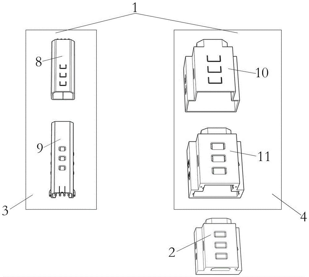
图1:实施例一的系列电性接口及转换件示意图Figure 1: Schematic diagram of a series of electrical interfaces and conversion parts of the first embodiment
图2:实施例一的系列电性接口剖视图Figure 2: Cross-sectional view of a series of electrical interfaces in the first embodiment
图3:实施例一的插座电性连接适配部分、胶芯柱、导电位列设面及插座导电件示意图Figure 3: Schematic diagram of the electrical connection adapter part of the socket, the rubber core column, the conductive position arrangement surface and the socket conductive parts of the first embodiment
图4:实施例一的插头电性连接适配部分、胶芯插孔、导电位列设面及插头导电件示意图Figure 4: Schematic diagram of the plug electrical connection adapter part, the rubber core jack, the conductive position arrangement surface and the plug conductive parts of the first embodiment
图5:实施例一的第一接口示意图Figure 5: Schematic diagram of the first interface of the first embodiment
图6:实施例一的第二接口示意图Figure 6: Schematic diagram of the second interface of the first embodiment
图7:实施例一的转换件示意图Figure 7: Schematic diagram of the conversion part of the first embodiment
图8:实施例一的转换件安装示意图Figure 8: Schematic diagram of the installation of the conversion part of the first embodiment
图9:实施例一的转换件安装剖面图Figure 9: Cross-sectional view of the installation of the conversion part of the first embodiment
图10:实施例二的移动电源与第一接口传输件组合形成的充电宝示意图Figure 10: Schematic diagram of the power bank formed by the combination of the mobile power supply and the first interface transmission member according to the second embodiment
图11:实施例二的移动电源与第一接口传输件组合形成的充电宝拆解示意图Figure 11: Schematic diagram of dismantling of the power bank formed by the combination of the mobile power supply and the first interface transmission member of the second embodiment
图12:实施例二的移动电源与第二接口传输件组合形成的充电宝示意图Figure 12: Schematic diagram of the power bank formed by the combination of the mobile power supply and the second interface transmission member according to the second embodiment
图13:实施例二的第二接口传输件拆解图Figure 13: Disassembled view of the second interface transmission member of the second embodiment
图14:实施例二的移动电源与第二接口传输件组合形成的充电宝拆解示意图Figure 14: Schematic diagram of dismantling of the power bank formed by the combination of the mobile power supply and the second interface transmission member of the second embodiment
图15:实施例二的第一接口传输件通过转换件与移动电源组合安装示意图Figure 15: Schematic diagram of the installation of the first interface transmission member in the second embodiment through the combination of the conversion member and the mobile power supply
图16:实施例二的故事机功能件与移动电源组合安装示意图Figure 16: Schematic diagram of the combined installation of the story machine functional parts and the mobile power supply in the second embodiment
图17:实施例三的系列电性接口及转换件示意图Figure 17: Schematic diagram of a series of electrical interfaces and conversion parts of the third embodiment
图18:实施例三的系列电性接口剖面图Figure 18: Cross-sectional view of a series of electrical interfaces in the third embodiment
图19:实施例三的第二接口示意图Figure 19: Schematic diagram of the second interface of the third embodiment
图20:实施例三的转换件示意图Figure 20: Schematic diagram of the conversion part of the third embodiment
图21:实施例三的转换件安装示意图Figure 21: Schematic diagram of the installation of the conversion part of the third embodiment
图22:实施例三的转换件安装剖面图Figure 22: Sectional view of the installation of the conversion part of the third embodiment
图23:实施例四的移动电源与第一接口、第二接口传输件组合形成的充电宝示意图Figure 23: Schematic diagram of the power bank formed by the combination of the mobile power supply, the first interface and the second interface transmission member according to the fourth embodiment
图24:实施例四的移动电源组合安装示意图Figure 24: Schematic diagram of the combined installation of the mobile power supply in the fourth embodiment
图25:实施例四的移动电源与第一接口、第二接口传输件组合形成的充电宝拆解示意图Figure 25: Schematic diagram of the disassembly of the power bank formed by the combination of the mobile power supply, the first interface and the second interface transmission member according to the fourth embodiment
图26:实施例四的风扇功能件通过转换件与移动电源组合安装示意图Figure 26: Schematic diagram of the installation of the fan function component of the fourth embodiment through the combination of the conversion component and the mobile power supply
图中:In the picture:
系列电性接口1、转换件2、第一接口3、第二接口4、第一插座8、第一插头9、第二插座10、第二插头11、转换件本体14、第一插座外壳16、第一插座胶芯17、插座电性连接适配部分18、第一插头外壳19、第一插头胶芯20、插头电性连接适配部分21、解锁开关24、第二插头外壳25、第二插头胶芯26、功能组件27、第二插座外壳28、第二插座胶芯29、胶芯柱30、胶芯插孔33、导电位列设面34、插座导电件35、导电位36、针脚37、第一V+38、第一Data-39、第一Data+40、GND41、V+输入42、第二Data+43、第二Data-44、第二V+45、插座卡口46、锁口47、插头卡口48、锁钩槽口49、卡簧扣50、锁钩51、插头导电件52、焊脚53、插头内腔54、法兰圈55、装配卡钩56、滑槽57、安装锁口58、通用卡口59、转换插孔60、解锁顶出孔61、插座内腔62、电性转换电路65、充电宝66、移动电源67、电源组件68、电源组件外壳69、电池70、电源组件功能电路71、充电口72、电源开关73、第一接口传输件75、第一接口传输组件76、第一接口传输组件外壳77、Type-A接口件78、第一移动电源79、第二移动电源81、安装位83、通用锁口85、风扇功能件97、风扇组件98、第二接口传输件105、第二接口传输组件106、第二接口传输组件外壳107、故事机功能件120、故事机组件121。Series
具体实施方式Detailed ways
下面详细描述本发明的实施例,所述实施例的示例在附图中示出,其中自始至终相同或类似的标号表示相同或类似的元件或具有相同或类似功能的元件。下面通过参考附图描述的实施例是示例性的,旨在用于解释本发明,而不能理解为对本发明的限制。The following describes in detail the embodiments of the present invention, examples of which are illustrated in the accompanying drawings, wherein the same or similar reference numerals refer to the same or similar elements or elements having the same or similar functions throughout. The embodiments described below with reference to the accompanying drawings are exemplary, and are intended to explain the present invention and should not be construed as limiting the present invention.
在本发明的描述中,需要理解的是,术语“长度”、“短于”、 “横截面”、“底部”、“上”、“外侧”、“内腔”、“头部”、“尾部”、等指示的方位或位置关系为基于附图所示的方位、位置或大小关系,仅是为了便于描述本发明和简化描述,而不是指示或暗示所指的装置或元件必须具有特定的方位、以特定的方位构造和操作,因此不能理解为对本发明的限制。由此,限定有“横截面”为垂直于插接方向的接口截面形状。此外,术语“第一”、“第二”、仅用于描述目的,而不能理解为指示或暗示相对重要性或者隐含指明所指示的技术特征的数量。由此,限定有“第一”、“第二”、的特征可以明示或者隐含地包括一个或者更多个该特征。In the description of the present invention, it should be understood that the terms "length", "shorter than", "cross-section", "bottom", "upper", "outside", "lumen", "head", " The orientation or positional relationship indicated by "tail", etc. is based on the orientation, position or size relationship shown in the drawings, and is only for the convenience of describing the present invention and simplifying the description, rather than indicating or implying that the indicated device or element must have a specific Orientation, construction and operation in a particular orientation, and therefore should not be construed as limiting the invention. Thus, a "cross-section" is defined as a cross-sectional shape of the interface perpendicular to the insertion direction. In addition, the terms "first" and "second" are used for descriptive purposes only, and should not be construed as indicating or implying relative importance or implying the number of indicated technical features. Thus, a feature defined as "first", "second", may expressly or implicitly include one or more of that feature.
在本发明中,除非另有明确的规定和限定,术语“安装”、“插接”、“连接”、“适配”、“接触”等术语应做广义理解,可以是固定连接,也可以是可拆卸连接,或成一体;可以是机械连接,也可以是电连接;可以是直接相连,也可以通过中间媒介间接相连,可以是两个元件内部的连通或两个元件的相互作用关系。对于本领域的普通技术人员而言,可以根据具体情况理解上述术语在本发明中的具体含义。In the present invention, unless otherwise expressly specified and limited, terms such as "installation", "plugging", "connection", "adaptation" and "contact" should be understood in a broad sense, which may be a fixed connection or a It can be a detachable connection or integrated; it can be a mechanical connection or an electrical connection; it can be a direct connection or an indirect connection through an intermediate medium, and it can be the internal communication between the two elements or the interaction relationship between the two elements. For those of ordinary skill in the art, the specific meanings of the above terms in the present invention can be understood according to specific situations.
实施例一Example 1
参照图1至图9,本实施例中例举了一种系列电性接口和其转换兼容的方法。Referring to FIG. 1 to FIG. 9 , a series of electrical interfaces and a method for converting them are exemplified in this embodiment.
所述系列电性接口1包括第一接口3、第二接口4;The series of
所述第一接口3、第二接口4通过转换件2转换兼容;The
所述第一接口3包括第一插座8、第一插头9,所述第一插座8与所述第一插头9适配插接,同时形成接口间的机械连接组合和接口间的电性连接电路;The
所述第一接口3包括锁止机构,以选配的锁止方式提高接口的连接可靠性;The
所述第二接口4包括第二插座10、第二插头11;所述第二插座10与所述第二插头11适配插接,同时形成接口间的机械连接组合和接口间的电性连接电路;The
所述第二接口4包括锁止机构,以选配的锁止方式提高接口的连接可靠性;The
所述第二接口4的横截面形状大于所述第一接口3的横截面形状,所述第二接口4的连接强度大于所述第一接口3的连接强度;The cross-sectional shape of the
所述第一接口3、第二接口4的插座电性连接适配部分18相同,所述第一接口3、第二接口4的插头电性连接适配部分21相同。The sockets of the
所述转换件2为纯机械结构,无电性电路;The
所述第二插座10通过与转换件2以机械结构组合配合的方式转换为能兼容插接所述第一插头9的兼容型插座,来适配插接所述第一插头9,形成兼容接口间的机械连接组合和兼容接口间的电性连接电路;The
所述系列电性接口1和转换件2均为定向连接;定向连接包括但不限于单向或多向的定向连接;单向或多向连接的定向方式包括但不限于通过接口的截面形状限定对应连接方向的方式、通过接口上的限位或定位构造限定对应连接方向的方式。The series of
本实施例所述系列电性接口1和转换件2均采用截面形状定向的方式实现单向定向连接,避免接口错接;The series of
优选的所述第一接口3的定向方式为接口横截面形状为单侧倒双角的矩形;The preferred orientation of the
优选的所述第二接口4和所述转换件2的定向方式为接口横截面形状为凸字形。The preferred orientation of the
所述第一插座8包括第一插座外壳16、第一插座胶芯17、插座导电件35;The
优选的,所述第一插座外壳16为金属外壳;Preferably, the
所述第一插座外壳16包括插座卡口46、锁口47;The
所述第一插座胶芯17安装于所述第一插座外壳16内的尾部;The first
所述第一插座胶芯17包括胶芯柱30、导电位列设面34;The first
所述第一插座胶芯17上设有插座导电件35;The first
所述插座导电件35包括导电位36、针脚37;The socket
优选的,所述插座导电件35的电性定义和排布序列为第一V+38、第一Data-39、第一Data+40、GND41、V+输入42、第二Data+43 、第二Data-44、第二V+45; 所述第一V+38和GND41作为第一组电源输出,可作为标准的电源输出,运用于充电宝等产品;所述第一Data-39和第一Data+40以及第二Data+43和第二Data-44作为两组数据信号传输电路实现接口的数据传输功能;所述第二V+45和GND41作为第二组电源输出,可作为特定电压或电路的电源输出运用于产品,提供更多的电源输出选择;所述V+输入42和GND41作为一组电源输入,可作为电源充电电路使用。Preferably, the electrical definition and arrangement sequence of the
所述导电位36按电性定义排序列设于所述第一插座8的导电位列设面34上;The
所述针脚37埋嵌在所述第一插座胶芯17中,并在所述第一插座8尾部延伸出,用于连接电路;The
所述第一插座8适配插接所述第一插头9,所述第一插座8用以实现电性连接的组件和/或结构的适配部分为插座电性连接适配部分18;所述插座电性连接适配部分18包括胶芯柱30、导电位列设面34、及列设于导电位列设面34上的导电位36。The
所述第一插头9包括第一插头外壳19、第一插头胶芯20、插头导电件52;The
所述第一插头外壳19包括焊脚53、插头卡口48、锁钩槽口49;The
所述焊脚53位于所述第一插头外壳19的尾部,用于连接功能组件27;The solder pins 53 are located at the tail of the
所述插头卡口48上可设有卡簧扣50,所述卡簧扣50与所述第一插座外壳16上的插座卡口46形成弹性卡扣,加强接口连接可靠性,防松防脱;The
所述锁钩槽口49上可设有锁钩51,所述锁钩51与所述第一插座外壳16上的锁口47形成刚性钩锁,锁止接口,确保接口连接可靠;所述锁钩51可通过解锁开关24控制解锁。The
所述第一插头胶芯20契合安装于所述第一插头外壳19内;The first
所述第一插头胶芯20的头部包括胶芯插孔33、导电位列设面34;The head of the first
所述第一插头胶芯20上设有插头导电件52;The first
优选的,所述插头导电件52的电性定义和排布序列为第一V+38、第一Data-39、第一Data+40、GND41、V+输入42、第二Data+43、第二Data-44、第二V+45;Preferably, the electrical definition and arrangement sequence of the
所述插头导电件52和所述插座导电件35的电性定义和排布序列相对应,可连接形成电性连接电路;The electrical definition and arrangement sequence of the plug
所述插头导电件52包括导电位36、针脚37;The plug
所述导电位36按电性定义和排序列设于所述第一插头9的导电位列设面34上;The
所述针脚37埋嵌在所述第一插头胶芯20中,并在所述第一插头9的尾部延伸或表露出,用于连接电路;The
所述第一插头9适配插接于所述第一插座8,所述第一插头9用以实现电性连接的组件和/或结构的适配部分为插头电性连接适配部分21;所述插头电性连接适配部分21包括胶芯插孔33、导电位列设面34、及列设于导电位列设面34上的具有电性定义和排布序列的导电位36;The
所述第一插头9与所述第一插座8插接连接时,使所述第一插头9的插头电性连接适配部分21与所述第一插座8的插座电性连接适配部分18适配连接,又使所述第一插头9的导电位36与所对应的所述第一插座9的导电位36接触导通,形成接口间的电性连接电路。When the
所述第二插座10包括第二插座外壳28、第二插座胶芯29、插座导电件35;The
所述第二插座外壳28包括插座内腔62、插座卡口46、锁口47;The
所述插座内腔62为所述第二插座10内的插口空腔;The socket
所述第二插座胶芯29包括胶芯柱30、导电位列设面34;The second
所述第二插座胶芯29安装于所述第二插座外壳28内的尾部 ;The second
所述第二插座胶芯29上设有插座导电件35;The second
所述第二插座10的插座导电件35与所述第一插座8的插座导电件35的电性定义和排布序列相同;The electrical definition and arrangement sequence of the socket
所述插座导电件35包括导电位36、针脚37;The socket
所述导电位36列设于所述导电位列设面34上;The
所述针脚37埋嵌在所述第二插座胶芯29中,并在所述第二插座10尾部延伸或表露出,用于连接电路;The
所述第二插座10可适配插接所述第二插头11,所述第二插座10用以实现电性连接的组件和/或结构的适配部分为插座电性连接适配部分18;所述插座电性连接适配部分18包括胶芯柱30、导电位列设面34、及列设于导电位列设面34上的具有电性定义和排布序列的导电位36。The
所述第二插头11包括第二插头外壳25、第二插头胶芯26、插头导电件52;The
所述第二插头外壳25包括插头卡口48、锁钩槽口49、插头内腔54;The
所述插头内腔54为所述第二插头外壳25形成的内腔空间;The
所述插头内腔54至少能容纳安装一个Type-A接口件78,且所述插头内腔54的横截面形状至少能容纳一个Type-A接口件78和一个所述第一插头9的横截面形状;The
所述第二插头胶芯26契合安装于所述第二插头外壳25头部;The second
所述第二插头胶芯26包括胶芯插孔33、导电位列设面34;The second
所述第二插头胶芯26上设有插头导电件52;The second
所述第二插头11的插头导电件52与所述第一插头9的插头导电件52的电性定义和排布序列相同;The electrical definition and arrangement sequence of the plug
所述插头导电件52包括导电位36、针脚37;The plug
所述导电位36列设于所述导电位列设面34上;The
所述针脚37埋嵌在所述第二插头胶芯26中,并在所述第二插头11的插头内腔54中延伸出,用于连接电路;The
所述第二插头11适配插接于所述第二插座10,所述第二插头11用以实现电性连接的组件和/或结构的适配部分为插头电性连接适配部分21;所述插头电性连接适配部分21包括胶芯插孔33、导电位列设面34、及列设于导电位列设面34上的具有电性定义和排布序列的导电位36。The
优选的,所述第二插头11的插头内腔54尾部的内壁上设有滑槽57和安装锁口58,用于连接功能组件27,所述功能组件27上设有法兰圈55,所述法兰圈55上设有装配卡钩56;Preferably, the inner wall of the rear end of the
所述法兰圈55与所述插头内腔54相适配;The
所述装配卡钩56与所述安装锁口58相适配;The mounting
所述法兰圈55插接于所述插头内腔54,使所述装配卡钩56顺着所述滑槽57进入安装锁口58,所述装配卡钩56与所述安装锁口58形成刚性锁止,实现功能组件27与第二插头11的稳固卡接。The
所述第二插头11与所述第二插座10插接连接时,使所述第二插头11的插头电性连接适配部分21与所述第二插座10的插座电性连接适配部分18适配连接,又使所述插头导电件52与所对应的所述插座导电件35接触导通,形成接口间的电性连接电路。When the
所述第二插座10能与所述转换件2组合形成适配所述第一插头9的兼容型插座;The
所述转换件2包括转换件本体14、转换插孔60;The
所述转换件本体14包括插头卡口48、锁钩槽口49、解锁顶出孔61;The
所述插头卡口48上可设有卡簧扣50,所述锁钩槽口49上可设有锁钩51;The
优选的,所述锁钩槽口49上设有锁钩51;Preferably, a
所述锁钩51对应所述第二插座10的锁口47形成刚性锁止;The locking
所述转换插孔60是由所述转换件本体14的结构形成或限定的贯通通道;The
所述转换插孔60的横截面形状适配于所述第一插头9的横截面形状,所述第一插头9可插接于所述转换插孔60内;The cross-sectional shape of the
所述转换插孔60的内壁上设有插座卡口46、锁口47;The inner wall of the
所述插座卡口46对应所述第一插头9的卡簧扣50形成弹性锁止,所述锁口47对应所述第一接口3插头的锁钩51形成刚性锁止;The
所述转换件2以分级锁止的方式加强所述第一插头9的连接可靠性;The
所述转换件本体14中无电性电路;There is no electrical circuit in the
所述系列电性接口1的转换兼容的方法,具体为所述转换件2与所述第二插座10的机械结构组合配合,所述转换件本体14的机械结构完全内嵌或部分插入所述第二插座10的插座内腔62,使所述转换件2与所述第二插座10形成机械连接,同时使所述转换插孔60位置对应于所述插座电性连接适配部分18,所述转换插孔60与所述第二插座10的插座电性连接适配部分18组合而成的插孔能适配所述第一插头9的插接,从而形成兼容型插座适配接插所述第一插头9,形成电性连接电路;The conversion-compatible method of the series of
通过所述解锁顶出孔61可解锁所述转换件2的锁钩51并拆卸转换件2。The
所述功能组件27能与所述第一插头9、所述第二插头11、所述第一插座8、所述第二插座10、中的至少一种连接,组合形成功能件;不同的功能组件27应用所述第一插头9或所述第二插头11时,可根据功能组件27的插接稳定性需求在所述第一插头9或所述第二插头11上选择安装卡簧扣50或锁钩51来加强连接可靠性,所述第二接口4既具有一定的机械强度可运用于电器的组合组装连接,同时也具有数字信号传输连接的功能。The
本实施例所述插座导电件35、插头导电件52的电性定义和排布序列包括但不限于本实施例的举例;The electrical definition and arrangement sequence of the socket
所述系列电性接口1和转换件2的锁止方式包括但不限于机械锁止或锁紧、磁吸、粘缠、弹性限位、旋紧、套箍中的任意一种或多种。本实施例所述系列电性接口1优选的锁止方式为所述插头和所述转换件2上设置的锁钩51和/或卡簧扣50,所述插座上设有与锁钩51对应的锁口47和与卡簧扣50对应的插座卡口46,所述的锁钩51或卡簧扣50可根据不同功能件的连接可靠性需求进行选用。The locking methods of the series of
本实施例所述系列电性接口1插头的安装方式包括但不限于焊脚连接、卡接连接、过渡段连接、与功能组件一体成型。The installation methods of the series of
实施例二
参照图1至图16,本实施例中例举了第一接口3、第二接口4的具体应用,其中包括移动电源。1 to 16 , specific applications of the
为便于描述,将应用第一接口3的移动电源命名为第一移动电源79;将应用第二接口4的移动电源命名为第二移动电源81;所述第一接口3为实施例一中所述的第一接口3被应用时的一种具体形式;所述第二接口4为实施例一中所述的第二接口4被应用时的一种具体形式。For the convenience of description, the mobile power supply using the
所述第一移动电源79,包括第一插座8、电源组件68;The first
所述电源组件68包括电源组件外壳69、电池70、电源组件功能电路71、充电口72、电源开关73;The
所述第一移动电源79可以适配连接第一接口传输件75,组合形成一种新型的充电宝66;The first
所述第一接口传输件75包括第一接口传输组件76、第一插头9;The first
所述第一接口传输组件76包括第一接口传输组件外壳77、Type-A接口件78;The first
所述Type-A接口件78契合安装于所述第一接口传输组件外壳77内;The Type-
所述Type-A接口件78的VCC针脚对应所述第一插头9的第一V+38,所述Type-A接口件78的GND针脚对应所述第一插头9的GND41,所述Type-A接口件78的DATA+针脚对应所述第一插头9的第一DATA+40, 所述Type-A接口件78的DATA-针脚对应所述第一插头9的第一DATA-39。所述第一插头9的电性定义为V+输入42、第二DATA+43、第二DATA-44、第二V+45的所述插头导电件52闲置;The VCC pin of the Type-
所述第一接口传输件75通过第一插头9插接于所述第一移动电源79的第一插座8上时,所述第一插头9上设有卡簧扣50,所述卡簧扣50对应所述第一插座8上的插座卡口46形成弹性限位。When the first
所述第二移动电源81包括电源组件68、第二插座10;The second
所述电源组件68包括电源组件外壳69、电池70、电源组件功能电路71、充电口72、电源开关73、Type-A接口件78;The
所述第二移动电源81可以适配连接第二接口传输件105,组合形成一种新型的充电宝66;The second
所述第二接口传输件105包括第二接口传输组件106、第二插头11;The second
所述第二接口传输组件106包括第二接口传输组件外壳107、接口件;The second
所述第二接口传输组件外壳107包括装配卡钩56,与所述第二插头11的安装锁口58配合,形成锁止;The second interface
接口件包括但不限于Type-A接口件、Type-C接口件、Micro USB接口件等;Interface parts include but are not limited to Type-A interface parts, Type-C interface parts, Micro USB interface parts, etc.;
优选的,接口件为Type-A接口件78;Preferably, the interface is Type-
所述Type-A接口件78内嵌安装于所述第二插头11的插头内腔54,所述Type-A接口件78与列座在所述插头内腔54内的针脚37连接,形成电性连接电路。The Type-
此外,所述第二插头11与其他传输组件连接时,可根据不同传输组件的电性电路需求,通过在所述插头内腔54里安装电性转换电路65,将所述第二插头11的电性电路进行转换,从而满足不同功能组件27的电性连接需求;In addition, when the
所述第二接口传输件105的第二插头11上设有卡簧扣50,所述第二接口传输件105插接于所述移动电源67的第二插座10上时,所述卡簧扣50与所述第二插座10的插座卡口46形成弹性锁止。The
所述第二移动电源81还可适配连接转换件2,所述转换件2为实施例一中的转换件2被应用时的一种具体形式;The second
所述转换件2嵌入式安装于所述第二移动电源81的第二插座10的插座内腔62中;The
所述转换件2与所述第二插座10组合形成适配第一插头9的兼容型插座;The
所述转换件2的锁钩51对应所述第二插座10的锁口47形成刚性锁止;The locking
所述转换件2的锁口47与所述第一插头9的锁钩51形成刚性锁止和/或转换件2的插座卡口46与第一插头9的卡簧扣50形成弹性锁止,以分级锁止的方式加强所述第一插头9的连接可靠性;The locking
所述转换件2在拆卸脱离所述移动电源67时,通过所述解锁顶出孔61解锁所述转换件2的锁钩51;When the
所述第一接口传输件75插接于由所述转换件2与所述第二插座10组合形成的兼容型插座上,使所述第一接口传输件75与所述转换件2、所述移动电源67组合形成一种新型的充电宝66。The first
所述移动电源67还可适配连接其他功能件,组合形成不同的功能产品,功能件包括但不限于学习机、电动玩具、电动工具;The
本实施例举例的功能件为故事机功能件120;The functional component exemplified in this embodiment is the story machine
所述故事机功能件120包括故事机组件121、第二插头11;The
所述第二插头11上设有锁钩51,所述故事机功能件120插接于所述第二移动电源81的第二插座10上时,所述锁钩51与所述第二插座10上的锁口47形成刚性锁止,所述故事机功能件120与所述移动电源67组合形成故事机;The
所述故事机组件121上设有解锁开关24,所述故事机功能件120在拆卸脱离所述第二移动电源81时,通过所述解锁开关24解锁所述锁钩51。The
实施例三
参照图3至图5、图17至图22,本实施例中例举了一种系列电性接口和其转换兼容的方法。Referring to FIGS. 3 to 5 and FIGS. 17 to 22 , a series of electrical interfaces and a method for converting them are exemplified in this embodiment.
所述系列电性接口1包括第一接口3、第二接口4;The series of
所述第一接口3、第二接口4通过转换件2转换兼容;The
所述第一接口3与实施例一中所描述的第一接口3相同;The
所述第二接口4包括第二插座10、第二插头11;所述第二插座10与所述第二插头11适配插接,同时形成接口间的机械连接组合和接口间的电性连接电路;The
所述第二接口4插接长度短于所述第一接口3的插接长度,所述第二接口4的横截面形状与第一接口3的横截面形状相同;The insertion length of the
所述第一接口3、第二接口4的插座电性连接适配部分18相同,所述第一接口3、第二接口4的插头电性连接适配部分21相同;The sockets of the
所述转换件2为纯机械结构,无电性电路;The
所述第二插座10通过与转换件2以机械结构组合配合的方式转换为能兼容插接所述第一插头9的兼容型插座,来适配插接所述第一插头9,形成兼容接口间的机械连接组合和兼容接口间的电性连接电路;The
所述系列电性接口1和转换件2均为定向连接;定向连接包括但不限于单向或多向的定向连接;单向或多向连接的定向方式包括但不限于通过接口的截面形状限定对应连接方向的方式、通过接口上的限位或定位构造限定对应连接方向的方式;The series of
本实施例所述系列电性接口1和转换件2均采用截面形状定向的方式实现单向定向连接,避免接口错接;The series of
优选的,所述第二接口4的定向方式为横截面形状为单侧倒双角的矩形;Preferably, the orientation of the
优选的,所述转换件2的定向方式为横接截面形状为单侧倒单角的矩形。Preferably, the orientation of the
所述第二插座10包括第二插座外壳28、第二插座胶芯29、插座导电件35;The
所述第二插座外壳28为金属外壳;The
所述第二插座胶芯29安装于所述第二插座外壳28内;the second
所述第二插座胶芯29包括胶芯柱30、导电位列设面34;The second
所述第二插座胶芯29上设有插座导电件35;The second
所述插座导电件35包括导电位36、针脚37;The socket
所述第二插座10的插座导电件35与所述第一插座8的插座导电件35的电性定义和排布序列相同;The electrical definition and arrangement sequence of the socket
所述针脚37埋嵌在所述第二插座胶芯29中,并在所述第二插座10尾部延伸出,用于连接电路;The
所述第二插座10适配插接所述第二插头11,所述第二插座10用以实现电性连接的组件和/或结构的适配部分为插座电性连接适配部分18;所述插座电性连接适配部分18包括胶芯柱30、导电位列设面34、及列设于导电位列设面34上的具有电性定义和排布序列的导电位36;The
所述第二插座10短于所述第一插座8;The
所述第二插座10的横截面形状与所述第一插座8的横截面形状相同。The cross-sectional shape of the
所述第二插头11包括第二插头外壳25、第二插头胶芯26、插头导电件52;The
所述第二插头外壳25为金属外壳;The
所述第二插头外壳25包括焊脚53,所述焊脚53位于所述第二插头外壳25的尾部,用于连接功能组件27;The
所述第二插头胶芯26契合安装于所述第二插头外壳25内;The second
所述第二插头胶芯26包括胶芯插孔33、导电位列设面34;The second
所述第二插头胶芯26上设有插头导电件52;The second
所述第二插头11的插头导电件52与所述第一插头9的插头导电件52的电性定义和排布序列相同;The electrical definition and arrangement sequence of the plug
所述插头导电件52包括导电位36、针脚37;The plug
所述导电位36列设于所述导电位列设面34上,且所述针脚37埋嵌在所述第二插头胶芯26中,并在所述第二插头11的尾部延伸或表露出,用于连接电路;The
所述第二插头11适配插接于所述第二插座10,所述第二插头11用以实现电性连接的组件和/或结构的适配部分为插头电性连接适配部分21;所述插头电性连接适配部分21包括胶芯插孔33、导电位列设面34、及列设于导电位列设面34上的具有电性定义和排布序列的导电位36;The
所述第二插头11短于所述第一插头9;The
所述第二插头11的横截面形状与所述第一插头9的横截面形状相同;The cross-sectional shape of the
所述第二插头11与所述第二插座10插接连接时,使所述第二插头11的插头电性连接适配部分21与所述第二插座10的插座电性连接适配部分18适配连接,又使所述插头导电件52与所对应的所述插座导电件35接触导通,形成接口间的电性连接电路。When the
所述第二插座10能与所述转换件2组合形成适配所述第一插头9的兼容型插座;The
所述转换件2包括转换件本体14、转换插孔60;The
所述转换件本体14包括解锁顶出孔61、通用卡口59;The
所述通用卡口59可安装所述卡簧扣50或所述锁钩51;The
优选的,转换件2的通用卡口59上设有锁钩51;Preferably, a locking
所述锁钩51对应外接安装所述转换件2的限位结构上的通用锁口85,形成刚性锁止The
所述转换插孔60是由所述转换件本体14的结构形成或限定的贯通通道;The
所述转换插孔60的横截面形状适配于所述第一插头9的横截面形状,可插接所述第一插头9;The cross-sectional shape of the
所述转换插孔60的内壁上设有插座卡口46、锁口47;The inner wall of the
所述插座卡口46对应所述第一插头9的卡簧扣50形成弹性锁止,所述锁口47对应所述第一插头9的锁钩51形成刚性锁止;The
所述转换件2以分级锁止的方式加强所述第一插头9的连接可靠性;The
所述转换件本体14中无电性电路;There is no electrical circuit in the
所述转换件2与所述第二插座10的机械结构形成组合配合,即以与所述第一插座8的机械结构进行直接连接的外接安装方式,和/或,所述转换件2被除所述第二插座10以外的组件结构所限位的外接安装方式组合组装在所述第二插座10上,并使所述转换插孔60位置对应于所述第二插座10的插座电性连接适配部分18,所述转换插孔60与所述第二插座10的插座电性连接适配部分18组合而成的插孔能适配所述第一插头9的插接,从而形成兼容型插座适配接插所述第一插头9,形成接口的机械连接和电性电路连接,实现了系列电性接口1间的转换兼容;The
所述转换件2的直接连接和被限位组合组装的外接安装方式包括但不限于套接、扣接、卡接、夹持、旋接。The external installation methods of the direct connection of the
通过所述解锁顶出孔61可解锁所述转换件2的锁钩51并拆卸所述转换件2;Through the unlocking
所述功能组件27能与所述第一插头9、所述第二插头11、所述第一插座8、所述第二插座10、中的至少一种连接,组合形成功能件;不同的功能组件27应用所述第一插头9时,可根据功能组件27的插接稳定性需求在所述第一插头9上选择安装卡簧扣50或锁钩51来加强连接强度。The
本实施例所述插座导电件35、插头导电件52的电性定义和排布序列包括但不限于本实施例的举例;The electrical definition and arrangement sequence of the socket
所述系列电性接口1和转换件2的锁止方式包括但不限于机械锁止或锁紧、磁吸、粘缠、弹性限位、旋紧、套箍中的任意一种或多种。本实施例所述系列电性接口1优选的锁止方式为所述插头和所述转换件2上设置的锁钩51和/或卡簧扣50,所述插座上设有与锁钩51对应的锁口47和与卡簧扣50对应的插座卡口46,所述的锁钩51或卡簧扣50可根据不同功能件的连接可靠性需求进行选用。The locking methods of the series of
本实施例所述系列电性接口1插头的安装方式包括但不限于焊脚连接、卡接连接、过渡段连接、与功能组件一体成型。The installation methods of the series of
实施例四
参照图17至图26,本实施例中例举了第一接口3和第二接口4的具体应用,其中包括移动电源67。Referring to FIGS. 17 to 26 , specific applications of the
所述第一接口3、第二接口4为实施例三中所述的第一接口3、第二接口4被应用时的一种具体形式;The
所述移动电源67包括电源组件68、第一插座8、第二插座10;The
所述电源组件68包括电源组件外壳69、电池70、电源组件功能电路71、充电口72、Type-A接口件78、安装位83;The
所述安装位83为电源组件外壳69形成的限位结构,所述安装位83包括通用锁口85,所述安装位83底部设有第二插座10;The
所述安装位83的通用锁口85用于与插接于安装位83上的功能件或转换件2的锁钩51对应连接形成刚性锁止,或与卡簧扣50对应连接形成弹性锁止;The
所述移动电源67可以适配连接第二接口传输件105、组合形成一种新型的充电宝66;The
所述移动电源67的安装位83适配插接所述第二接口传输件105;The
所述第二接口传输件105接插于所述安装位83的横截面外轮廓与所述转换件2的横截面外轮廓相同;The outer contour of the cross-section of the second
所述第二接口传输件105包括第二接口传输组件106、第二插头11;The second
所述第二接口传输组件106包括所述第二接口传输组件外壳107、Type-A接口件78;The second
所述第二接口传输组件外壳107包括通用卡口59、解锁顶出孔61;The second interface
所述通用卡口59上设有所述卡簧扣50,对应所述安装位83上的通用锁口85,形成弹性锁止;The
所述第二接口传输件105在拆卸脱离所述移动电源67时,通过解锁顶出孔61顶出;When the second
所述第二接口传输件105嵌入式插接于安装位83,所述第二插头11与安装位83上的第二插座10适配插接,形成电性连接电路,实现接口功能。The second
所述移动电源67的安装位83还可适配转换件2;The
所述转换件2定向并嵌入插接于所述安装位83上,所述安装位83限定了转换件2的插入方向,使所述转换插孔60位置对应于所述第二插座10的插座电性连接适配部分18,所述转换件2与所述安装位83中的第二插座10组合形成适配第一插头9的兼容型插座;The
所述转换件2的锁钩51与安装位83上的通用锁口85形成刚性锁止;所述转换件2的锁口47与所述第一插头9的锁钩51形成刚性锁止,和/或所述转换件2的插座卡口46与第一插头9的卡簧扣50形成弹性锁止,以分级锁止的方式加强所述第一插头9与兼容型插座的连接可靠性;The locking
所述转换件2在拆卸脱离所述移动电源67时,通过所述解锁顶出孔61解锁所述转换件2的锁钩51并顶出。When the
所述移动电源67还可通过其上所设的第二插座10、第一插座8和连接在所述第二插座10上的转换件2,适配连接其他功能件,组合形成不同的功能产品;功能件包括但不限于风扇、电动玩具、电动工具。The
本实施例举的功能件为风扇功能件97;The functional component exemplified in this embodiment is the fan
所述风扇功能件97包括风扇组件98、第一插头9;The
所述第一插头9上设有锁钩51,所述风扇功能件97插接于由所述转换件2与所述安装位83上的第二插座10组合形成的兼容型插座上时,所述锁钩51与所述安装位83上的锁口47形成刚性锁止,所述风扇功能件97与所述移动电源67组合组装;The
所述风扇组件98上设有解锁开关24,所述风扇功能件97在拆卸脱离所述移动电源67时,通过所述解锁开关24解锁所述锁钩51。The
本发明的上述具体实施例仅仅是为了说明本发明所作的举例,所述一种系列电性接口和其转换兼容的方法可运用的领域不局限于移动电源,还可包括所有仅需电力传输或需要数字信号传输的电器。The above-mentioned specific embodiments of the present invention are only examples to illustrate the present invention, and the applicable fields of the series of electrical interfaces and their conversion-compatible methods are not limited to mobile power supplies, but also include all types of electrical interfaces that only require power transmission or Appliances that require digital signal transmission.
本发明的上述具体实施例仅仅是为了说明本发明所作的举例,所述一种系列电性接口和其转换兼容的方法可应用的领域不局限于移动电源,还可包括所有仅需电力传输或需要数字信号传输的电器和设备。The above-mentioned specific embodiments of the present invention are only examples to illustrate the present invention, and the applicable fields of the series of electrical interfaces and their conversion-compatible methods are not limited to mobile power sources, but also include all types of electrical interfaces that only require power transmission or Appliances and equipment that require digital signal transmission.
应理解的是,上面的描述的目的是说明而不是限制。在阅读上面的描述时,除了提供的示例外许多实施例和应用都是显而易见的。本发明的范围应参照所附权利要求以及与权利要求所要求的权利等效的全部范围而确定,而不是参照上面的说明而确定。可以预期的是这里所讨论的领域将出现进一步的发展,并且所公开的系统和方法将可以结合到这样的未来的实施例中。本领域的普通技术人员应当理解:其依然可以对前述各实施例所记载的技术方案进行修改,或者对其中部分技术特征进行等同替换;而这些修改或者替换,并不能使相应技术方案的本质脱离本申请各实施例的技术方案的范围。It should be understood that the above description is intended to be illustrative and not restrictive. In addition to the examples provided, many embodiments and applications will be apparent upon reading the above description. The scope of the invention should be determined with reference to the appended claims, along with the full scope of equivalents to which such claims are entitled, rather than with reference to the above description. It is anticipated that further developments in the fields discussed herein will occur and that the disclosed systems and methods may be incorporated into such future embodiments. Those of ordinary skill in the art should understand that they can still modify the technical solutions described in the foregoing embodiments, or perform equivalent replacements to some of the technical features; and these modifications or replacements cannot make the corresponding technical solutions deviate from the essence The scope of the technical solutions of the embodiments of the present application.
Claims (13)
Priority Applications (1)
| Application Number | Priority Date | Filing Date | Title |
|---|---|---|---|
| CN202010797181.0A CN111834783A (en) | 2020-08-10 | 2020-08-10 | A series of electrical interface and its conversion compatible method and application |
Applications Claiming Priority (1)
| Application Number | Priority Date | Filing Date | Title |
|---|---|---|---|
| CN202010797181.0A CN111834783A (en) | 2020-08-10 | 2020-08-10 | A series of electrical interface and its conversion compatible method and application |
Publications (1)
| Publication Number | Publication Date |
|---|---|
| CN111834783A true CN111834783A (en) | 2020-10-27 |
Family
ID=72919757
Family Applications (1)
| Application Number | Title | Priority Date | Filing Date |
|---|---|---|---|
| CN202010797181.0A Pending CN111834783A (en) | 2020-08-10 | 2020-08-10 | A series of electrical interface and its conversion compatible method and application |
Country Status (1)
| Country | Link |
|---|---|
| CN (1) | CN111834783A (en) |
Citations (5)
| Publication number | Priority date | Publication date | Assignee | Title |
|---|---|---|---|---|
| CN202997245U (en) * | 2012-11-12 | 2013-06-12 | 林伟进 | USB multi-purpose adapter |
| CN204407650U (en) * | 2015-02-03 | 2015-06-17 | 建准电机工业股份有限公司 | Adapter device for charging applied to protective case |
| CN107732540A (en) * | 2017-10-16 | 2018-02-23 | 中国南方电网有限责任公司超高压输电公司贵阳局 | A type-A USB physical isolation interface converter |
| CN208315875U (en) * | 2018-05-31 | 2019-01-01 | 深圳市金迈高智能科技有限公司 | A kind of split type charging connector |
| CN208385691U (en) * | 2018-07-26 | 2019-01-15 | 深圳市优耐尔电子科技有限公司 | A kind of detachable DC adapter |
-
2020
- 2020-08-10 CN CN202010797181.0A patent/CN111834783A/en active Pending
Patent Citations (5)
| Publication number | Priority date | Publication date | Assignee | Title |
|---|---|---|---|---|
| CN202997245U (en) * | 2012-11-12 | 2013-06-12 | 林伟进 | USB multi-purpose adapter |
| CN204407650U (en) * | 2015-02-03 | 2015-06-17 | 建准电机工业股份有限公司 | Adapter device for charging applied to protective case |
| CN107732540A (en) * | 2017-10-16 | 2018-02-23 | 中国南方电网有限责任公司超高压输电公司贵阳局 | A type-A USB physical isolation interface converter |
| CN208315875U (en) * | 2018-05-31 | 2019-01-01 | 深圳市金迈高智能科技有限公司 | A kind of split type charging connector |
| CN208385691U (en) * | 2018-07-26 | 2019-01-15 | 深圳市优耐尔电子科技有限公司 | A kind of detachable DC adapter |
Similar Documents
| Publication | Publication Date | Title |
|---|---|---|
| TWI769669B (en) | Electrical connector | |
| JP3141351U (en) | Micro-type universal serial bus connector | |
| US20070243741A1 (en) | Plug/unplug moudle base | |
| JP3994058B2 (en) | Latch system for electrical connectors | |
| US8435078B2 (en) | Electrical connector structure with multi-poles | |
| CN217823350U (en) | Wire end connector and connector assembly | |
| CN216161956U (en) | Plug connector and connector assembly | |
| CN113823943B (en) | High vibration resistance energy storage wire of interior round spring formula card line is to connector | |
| CN212784125U (en) | Serial universal electrical interface and application thereof | |
| CN221727483U (en) | Circuit board components and electrical equipment | |
| CN215579210U (en) | Female seat, male head and interface functional part of electrical interface | |
| CN108063354A (en) | Anthropomorphic robot and function expanding module | |
| CN117154441B (en) | High-frequency two-in-one connector assembly | |
| CN119209069A (en) | High-current connector with plate end and wire end combined | |
| CN114597720B (en) | A conductive connector and connector assembly | |
| CN214797824U (en) | Horizontal public head end connector of round port | |
| CN212115856U (en) | Controller | |
| CN210468182U (en) | Plug connector, connector assembly, circuit board module and electronic equipment | |
| CN219535008U (en) | Pin assembly and electronic equipment | |
| CN223109281U (en) | A spliced assembled connector male head, a spliced assembled connector female head and a connector assembly | |
| CN114188747B (en) | Power Adapter | |
| CN212136788U (en) | Single-key pressing assembly and connector thereof | |
| CN222600361U (en) | An experimental development board with a magnetic interface | |
| CN222995895U (en) | Dual-purpose plug connector | |
| CN222395092U (en) | An easily disassembled electrical connector |
Legal Events
| Date | Code | Title | Description |
|---|---|---|---|
| PB01 | Publication | ||
| PB01 | Publication | ||
| SE01 | Entry into force of request for substantive examination | ||
| SE01 | Entry into force of request for substantive examination | ||
| WD01 | Invention patent application deemed withdrawn after publication | ||
| WD01 | Invention patent application deemed withdrawn after publication |
Application publication date: 20201027 |