CN111828950A - A flue gas waste heat utilization system - Google Patents
A flue gas waste heat utilization system Download PDFInfo
- Publication number
- CN111828950A CN111828950A CN202010796317.6A CN202010796317A CN111828950A CN 111828950 A CN111828950 A CN 111828950A CN 202010796317 A CN202010796317 A CN 202010796317A CN 111828950 A CN111828950 A CN 111828950A
- Authority
- CN
- China
- Prior art keywords
- flue gas
- waste heat
- outlet
- condensate
- utilization system
- Prior art date
- Legal status (The legal status is an assumption and is not a legal conclusion. Google has not performed a legal analysis and makes no representation as to the accuracy of the status listed.)
- Pending
Links
Images

Classifications
-
- F—MECHANICAL ENGINEERING; LIGHTING; HEATING; WEAPONS; BLASTING
- F22—STEAM GENERATION
- F22D—PREHEATING, OR ACCUMULATING PREHEATED, FEED-WATER FOR STEAM GENERATION; FEED-WATER SUPPLY FOR STEAM GENERATION; CONTROLLING WATER LEVEL FOR STEAM GENERATION; AUXILIARY DEVICES FOR PROMOTING WATER CIRCULATION WITHIN STEAM BOILERS
- F22D1/00—Feed-water heaters, i.e. economisers or like preheaters
- F22D1/36—Water and air preheating systems
-
- F—MECHANICAL ENGINEERING; LIGHTING; HEATING; WEAPONS; BLASTING
- F23—COMBUSTION APPARATUS; COMBUSTION PROCESSES
- F23J—REMOVAL OR TREATMENT OF COMBUSTION PRODUCTS OR COMBUSTION RESIDUES; FLUES
- F23J15/00—Arrangements of devices for treating smoke or fumes
- F23J15/06—Arrangements of devices for treating smoke or fumes of coolers
-
- Y—GENERAL TAGGING OF NEW TECHNOLOGICAL DEVELOPMENTS; GENERAL TAGGING OF CROSS-SECTIONAL TECHNOLOGIES SPANNING OVER SEVERAL SECTIONS OF THE IPC; TECHNICAL SUBJECTS COVERED BY FORMER USPC CROSS-REFERENCE ART COLLECTIONS [XRACs] AND DIGESTS
- Y02—TECHNOLOGIES OR APPLICATIONS FOR MITIGATION OR ADAPTATION AGAINST CLIMATE CHANGE
- Y02E—REDUCTION OF GREENHOUSE GAS [GHG] EMISSIONS, RELATED TO ENERGY GENERATION, TRANSMISSION OR DISTRIBUTION
- Y02E20/00—Combustion technologies with mitigation potential
- Y02E20/30—Technologies for a more efficient combustion or heat usage
Landscapes
- Engineering & Computer Science (AREA)
- Mechanical Engineering (AREA)
- General Engineering & Computer Science (AREA)
- Physics & Mathematics (AREA)
- Thermal Sciences (AREA)
- Air Supply (AREA)
Abstract
本发明公开了一种烟气余热利用系统,属于火电机组节能减排领域,该烟气余热利用系统的烟气冷却器上设有连通的凝结水进口a1和凝结水出口a2;凝结水进水管路的进水端与低压加热器管路连通,凝结水进水管路的出水端与凝结水进口a1连通,凝结水回水管路的进水端与凝结水出口a2连通,凝结水回水管路的出水端与低压加热器管路连通;暖风器上设有连通的凝结水进口b1和凝结水出口b2,及连通的冷风进口和热风出口,凝结水进口b1与凝结水出口a2连通,凝结水出口b2连通于凝结水回水管路;冷风进口与送风机连通,热风出口与空气预热器连通。该烟气余热利用系统实现了锅炉烟气余热的梯级利用,锅炉热效率提高;同时能防止暖风器热风出口处的热风超温。
The invention discloses a flue gas waste heat utilization system, which belongs to the field of energy saving and emission reduction of thermal power units. A flue gas cooler of the flue gas waste heat utilization system is provided with a condensed water inlet a1 and a condensed water outlet a2 that are connected; a condensed water inlet pipe The water inlet end of the circuit is connected with the low pressure heater pipeline, the water outlet end of the condensate water inlet pipe is connected with the condensate water inlet a1, the water inlet end of the condensate water return line is connected with the condensate water outlet a2, and the condensate water return line is connected with the condensate water outlet a2. The water outlet is connected with the low-pressure heater pipeline; the air heater is provided with a connected condensate inlet b1 and a condensate outlet b2, and a connected cold air inlet and a hot air outlet. The condensate inlet b1 is communicated with the condensate outlet a2, and the condensate The outlet b2 is communicated with the condensed water return pipeline; the cold air inlet is communicated with the blower, and the hot air outlet is communicated with the air preheater. The flue gas waste heat utilization system realizes the cascade utilization of the boiler flue gas waste heat, improves the thermal efficiency of the boiler, and at the same time can prevent the hot air at the hot air outlet of the heater from overheating.
Description
技术领域technical field
本发明涉及火电机组节能减排技术领域,尤其涉及一种烟气余热利用系统。The invention relates to the technical field of energy saving and emission reduction of thermal power units, in particular to a system for utilizing waste heat of flue gas.
背景技术Background technique
在我国火力发电厂中,锅炉总体热损失的70%~80%为排烟热损失。排烟温度每上升10℃~15℃,锅炉效率将下降1%,年平均标煤耗随之上升3~4g/(kW·h)。随着节能减排政策的日益严格和能源价格的不断攀升,合理利用锅炉烟气余热的重要性日益增加。In my country's thermal power plants, 70% to 80% of the overall heat loss of the boiler is exhaust heat loss. When the exhaust gas temperature rises by 10℃~15℃, the boiler efficiency will decrease by 1%, and the annual average standard coal consumption will increase by 3~4g/(kW·h). With the increasingly strict energy conservation and emission reduction policies and rising energy prices, the importance of rational utilization of boiler flue gas waste heat is increasing.
传统的烟气余热利用方式中最常用的方式是在空气预热器之后的尾部烟道中布置低温省煤器,利用烟气余热加热回热系统中的冷凝水,以减少回热系统的抽汽量;节省的抽汽进入后续汽轮机内继续膨胀做功,汽机总出功增加,从而提高整个机组的经济性。The most common method of traditional flue gas waste heat utilization is to arrange a low-temperature economizer in the tail flue after the air preheater, and use the flue gas waste heat to heat the condensed water in the regenerative system to reduce the extraction steam of the regenerative system. The saved extraction steam enters the subsequent steam turbine to continue to expand and do work, and the total output of the steam turbine increases, thereby improving the economy of the entire unit.
以上烟气余热利用方案主要存在以下缺点:The above-mentioned flue gas waste heat utilization schemes mainly have the following disadvantages:
(1)一级余热利用系统吸收的烟气余热直接用于加热烟囱入口的烟气,造成能源浪费。(1) The waste heat of flue gas absorbed by the primary waste heat utilization system is directly used to heat the flue gas at the entrance of the chimney, resulting in energy waste.
(2)夏季工况,锅炉排烟温度高,二级烟气余热回收系统回收热量增大,容易造成暖风器出口热风超温。(2) In summer working conditions, the exhaust gas temperature of the boiler is high, and the heat recovered by the secondary flue gas waste heat recovery system increases, which is likely to cause the hot air at the heater outlet to overheat.
(3)低温省煤器回收的烟气余热只加热凝结水,烟气余热未实现梯级利用,余热利用率低。(3) The waste heat of flue gas recovered by the low-temperature economizer only heats the condensed water, and the waste heat of flue gas has not been utilized in cascade, and the utilization rate of waste heat is low.
因此,亟需提出一种烟气余热利用系统来解决现有技术中存在的上述技术问题。Therefore, there is an urgent need to propose a flue gas waste heat utilization system to solve the above technical problems existing in the prior art.
发明内容SUMMARY OF THE INVENTION
本发明的目的在于提供一种烟气余热利用系统,能实现烟气余热的梯级利用,能源利用率高,且能够避免暖风器出口热风超温。The purpose of the present invention is to provide a flue gas waste heat utilization system, which can realize the cascade utilization of flue gas waste heat, has high energy utilization rate, and can avoid overheating of hot air at the outlet of the heater.
为实现上述目的,本发明所采用的技术方案是:For achieving the above object, the technical scheme adopted in the present invention is:
一种烟气余热利用系统,包括送风机、空气预热器、低压加热器组、凝结水进水管路、凝结水回水管路、烟气冷却器、暖风器和烟气处理装置;A flue gas waste heat utilization system, comprising a blower, an air preheater, a low-pressure heater group, a condensate water inlet pipeline, a condensate water return pipeline, a flue gas cooler, an air heater and a flue gas treatment device;
所述低压加热器组包括多个低压加热器,多个所述低压加热器通过低压加热器管路依次连通;所述低压加热器管路的进水端连通于凝结水水源,所述低压加热器管路的出水端连通于除氧器;The low-pressure heater group includes a plurality of low-pressure heaters, and the plurality of low-pressure heaters are connected in sequence through the low-pressure heater pipeline; the water inlet end of the low-pressure heater pipeline is connected to the condensed water source, and the low-pressure heater The outlet end of the deaerator pipeline is connected to the deaerator;
所述烟气冷却器上设有相互连通的凝结水进口a1和凝结水出口a2,以及相互连通的烟气进口和烟气出口;所述凝结水进水管路的进水端与所述低压加热器管路连通,所述凝结水进水管路的出水端与所述凝结水进口a1连通,所述凝结水回水管路的进水端与所述凝结水出口a2连通,所述凝结水回水管路的出水端与所述低压加热器管路连通;所述烟气进口与所述空气预热器连通,所述烟气出口与所述烟气处理装置连通;The flue gas cooler is provided with a condensed water inlet a1 and a condensed water outlet a2 that communicate with each other, and a flue gas inlet and a flue gas outlet that communicate with each other; the water inlet end of the condensed water inlet pipeline is connected to the low pressure heating The water outlet end of the condensate water inlet pipe is communicated with the condensate water inlet a1, the water inlet end of the condensate water return pipe is communicated with the condensate water outlet a2, and the condensate water return pipe The water outlet end of the road is communicated with the low-pressure heater pipeline; the flue gas inlet is communicated with the air preheater, and the flue gas outlet is communicated with the flue gas treatment device;
所述暖风器上设有相互连通的凝结水进口b1和凝结水出口b2,以及相互连通的冷风进口和热风出口,所述凝结水进口b1与所述凝结水出口a2连通,所述凝结水出口b2连通于所述凝结水回水管路;所述冷风进口与所述送风机连通,所述热风出口与所述空气预热器连通。The air heater is provided with a condensed water inlet b1 and a condensed water outlet b2 that communicate with each other, and a cold air inlet and a hot air outlet that communicate with each other. The condensed water inlet b1 is communicated with the condensed water outlet a2, and the condensed water The outlet b2 is communicated with the condensate water return pipeline; the cold air inlet is communicated with the blower, and the hot air outlet is communicated with the air preheater.
作为上述烟气余热利用系统的优选技术方案,所述烟气余热利用系统还包括:As the preferred technical solution of the above-mentioned flue gas waste heat utilization system, the flue gas waste heat utilization system also includes:
凝结水进水调节阀,所述凝结水进水调节阀设置于所述凝结水进水管路中。A condensate water inlet regulating valve, the condensate water inlet regulating valve is arranged in the condensate water inlet pipeline.
作为上述烟气余热利用系统的优选技术方案,所述烟气余热利用系统还包括:As the preferred technical solution of the above-mentioned flue gas waste heat utilization system, the flue gas waste heat utilization system also includes:
热水再循环回路,所述热水再循环回路的进水端连通于所述凝结水回水管路,所述热水再循环回路的出水端连通于所述凝结水进水管路。A hot water recirculation circuit, the water inlet end of the hot water recirculation circuit is connected to the condensate water return pipeline, and the water outlet end of the hot water recirculation circuit is connected to the condensate water inlet pipeline.
作为上述烟气余热利用系统的优选技术方案,所述烟气余热利用系统还包括:As the preferred technical solution of the above-mentioned flue gas waste heat utilization system, the flue gas waste heat utilization system also includes:
再循环调节阀,设置于所述热水再循环回路中。A recirculation regulating valve is arranged in the hot water recirculation circuit.
作为上述烟气余热利用系统的优选技术方案,所述烟气余热利用系统还包括:As the preferred technical solution of the above-mentioned flue gas waste heat utilization system, the flue gas waste heat utilization system also includes:
凝结水回水调节阀,设置于所述凝结水回水管路中。The condensate water return regulating valve is arranged in the condensate water return pipeline.
作为上述烟气余热利用系统的优选技术方案,所述烟气余热利用系统还包括:As the preferred technical solution of the above-mentioned flue gas waste heat utilization system, the flue gas waste heat utilization system also includes:
变频增压水泵,设置于所述凝结水进水管路中。The variable frequency booster pump is arranged in the condensate water inlet pipeline.
作为上述烟气余热利用系统的优选技术方案,所述烟气冷却器为逆流布置的翅片管式换热器。As a preferred technical solution of the above-mentioned flue gas waste heat utilization system, the flue gas cooler is a fin-and-tube heat exchanger arranged in a countercurrent flow.
作为上述烟气余热利用系统的优选技术方案,所述暖风器为逆流布置的螺旋翅片管式换热器。As a preferred technical solution of the above-mentioned flue gas waste heat utilization system, the air heater is a spiral fin-and-tube heat exchanger arranged in a countercurrent flow.
作为上述烟气余热利用系统的优选技术方案,所述烟气冷却器的所述烟气出口的烟气温度为90℃-100℃,烟气阻力为100Pa-800Pa。As a preferred technical solution of the above-mentioned flue gas waste heat utilization system, the flue gas temperature at the flue gas outlet of the flue gas cooler is 90°C-100°C, and the flue gas resistance is 100Pa-800Pa.
作为上述烟气余热利用系统的优选技术方案,所述暖风器的所述热风出口的空气温度为50℃-90℃,空气阻力为100Pa-800Pa。As a preferred technical solution of the above-mentioned flue gas waste heat utilization system, the air temperature of the hot air outlet of the heater is 50°C-90°C, and the air resistance is 100Pa-800Pa.
与现有技术相比,本发明的有益效果为:Compared with the prior art, the beneficial effects of the present invention are:
本发明提出的烟气余热利用系统,通过协调余热、回热、暖风器系统对烟气余热进行高效回收利用,相较于常规电站锅炉系统,实现了锅炉烟气余热的梯级有效利用,锅炉热效率提高,实现能源的高效利用;同时,该烟气余热利用系统通过烟气冷却器加热凝结水,升温后的凝结水进入暖风器中加热送风机引入的一次风或二次风,可有效防止暖风器热风出口处的热风超温,还可以避免常规回收排烟系统加热热风时导致空气预热器占地面积过大难于布置的弊端。The flue gas waste heat utilization system proposed by the present invention efficiently recovers and utilizes the flue gas waste heat by coordinating the waste heat, recuperation, and air heater systems. The thermal efficiency is improved, and the efficient utilization of energy is realized; at the same time, the flue gas waste heat utilization system heats the condensed water through the flue gas cooler, and the heated condensed water enters the air heater to heat the primary air or secondary air introduced by the blower, which can effectively prevent The hot air at the hot air outlet of the heater is overheated, which can also avoid the disadvantage that the air preheater occupies an excessively large area and is difficult to arrange when the conventional smoke recovery and exhaust system heats the hot air.
附图说明Description of drawings
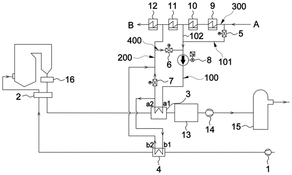
图1是本发明具体实施方式提供的烟气余热利用系统的示意图。FIG. 1 is a schematic diagram of a flue gas waste heat utilization system provided by a specific embodiment of the present invention.
图中:In the picture:
1、送风机;2、空气预热器;3、烟气冷却器;4、暖风器;5、凝结水进水调节阀;6、再循环调节阀;7、凝结水回水调节阀;8、变频增压水泵;9、第一低压加热器;10、第二低压加热器;11、第三低压加热器;12、第四低压加热器;13、静电除尘器;14、引风机;15、脱硫塔;16、省煤器;1. Blower; 2. Air preheater; 3. Flue gas cooler; 4. Air heater; 5. Condensate inlet control valve; 6. Recirculation control valve; 7. Condensate return control valve; 8 , variable frequency booster water pump; 9, first low pressure heater; 10, second low pressure heater; 11, third low pressure heater; 12, fourth low pressure heater; 13, electrostatic precipitator; 14, induced draft fan; 15 , desulfurization tower; 16, economizer;
100、凝结水进水管路;101、第一进水支路;102、第二进水支路;200、凝结水回水管路;300、低压加热器管路;400、热水再循环回路。100, condensate water inlet pipeline; 101, first water inlet branch; 102, second water inlet branch; 200, condensate return pipeline; 300, low pressure heater pipeline; 400, hot water recirculation circuit.
具体实施方式Detailed ways
为使本发明解决的技术问题、采用的技术方案和达到的技术效果更加清楚,下面结合附图并通过具体实施方式来进一步说明本发明的技术方案。可以理解的是,此处所描述的具体实施例仅仅用于解释本发明,而非对本发明的限定。另外还需要说明的是,为了便于描述,附图中仅示出了与本发明相关的部分而非全部。In order to make the technical problems solved by the present invention, the technical solutions adopted and the technical effects achieved more clearly, the technical solutions of the present invention are further described below with reference to the accompanying drawings and through specific embodiments. It should be understood that the specific embodiments described herein are only used to explain the present invention, but not to limit the present invention. In addition, it should be noted that, for the convenience of description, the accompanying drawings only show some but not all of the parts related to the present invention.
在本发明的描述中,除非另有明确的规定和限定,术语“相连”、“连接”、“固定”应做广义理解,例如,可以是固定连接,也可以是可拆卸连接,或成一体;可以是机械连接,也可以是电连接;可以是直接相连,也可以通过中间媒介间接相连,可以是两个元件内部的连通或两个元件的相互作用关系。对于本领域的普通技术人员而言,可以具体情况理解上述术语在本发明中的具体含义。In the description of the present invention, unless otherwise expressly specified and limited, the terms "connected", "connected" and "fixed" should be understood in a broad sense, for example, it may be a fixed connection, a detachable connection, or an integrated ; It can be a mechanical connection or an electrical connection; it can be a direct connection or an indirect connection through an intermediate medium, and it can be the internal connection of two elements or the interaction relationship between the two elements. For those of ordinary skill in the art, the specific meanings of the above terms in the present invention can be understood in specific situations.
在本发明中,除非另有明确的规定和限定,第一特征在第二特征之“上”或之“下”可以包括第一和第二特征直接接触,也可以包括第一和第二特征不是直接接触而是通过它们之间的另外的特征接触。而且,第一特征在第二特征“之上”、“上方”和“上面”包括第一特征在第二特征正上方和斜上方,或仅仅表示第一特征水平高度高于第二特征。第一特征在第二特征“之下”、“下方”和“下面”包括第一特征在第二特征正下方和斜下方,或仅仅表示第一特征水平高度小于第二特征。In the present invention, unless otherwise expressly specified and limited, a first feature "on" or "under" a second feature may include the first and second features in direct contact, or may include the first and second features Not directly but through additional features between them. Also, the first feature being "above", "over" and "above" the second feature includes the first feature being directly above and obliquely above the second feature, or simply means that the first feature is level higher than the second feature. The first feature is "below", "below" and "below" the second feature includes the first feature being directly below and diagonally below the second feature, or simply means that the first feature has a lower level than the second feature.
在本实施例的描述中,术语“上”“下”“左”“右”等方位或位置关系为基于附图所示的方位或位置关系,仅是为了便于描述和简化操作,而不是指示或暗示所指的装置或元件必须具有特定的方位、以特定的方位构造和操作,因此不能理解为对本发明的限制。此外,术语“第一”、“第二”仅仅用于在描述上加以区分,并没有特殊的含义。In the description of this embodiment, the terms "up", "down", "left", "right" and other azimuth or positional relationships are based on the azimuth or positional relationship shown in the drawings, which are only for convenience of description and simplification of operations, rather than indicating Or imply that the device or element referred to must have a particular orientation, be constructed and operate in a particular orientation, and therefore should not be construed as limiting the invention. In addition, the terms "first" and "second" are only used for distinction in description, and have no special meaning.
如图1所示,本实施例公开了一种协调余热、回热、暖风器系统的烟气余热利用系统,能有效降低燃煤发电机组煤耗以及提高锅炉效率,实现能源的高效利用。同时,该烟气余热利用系统可有效防止暖风器4热风出口处的热风超温,还可以避免常规回收排烟系统加热热风时导致空气预热器2占地面积过大难于布置的弊端。该烟气余热利用系统主要包括送风机1、空气预热器2、低压加热器组、凝结水进水管路100、凝结水回水管路200、烟气冷却器3、暖风器4和烟气处理装置。As shown in FIG. 1 , this embodiment discloses a flue gas waste heat utilization system that coordinates waste heat, recuperation, and air heater systems, which can effectively reduce coal consumption of coal-fired generator sets and improve boiler efficiency to achieve efficient energy utilization. At the same time, the flue gas waste heat utilization system can effectively prevent the hot air at the hot air outlet of the heater 4 from overheating, and can also avoid the disadvantage that the
具体地,低压加热器组包括多个低压加热器,多个低压加热器通过低压加热器管路300依次连通;低压加热器管路300的进水端(如图1中所示的A)连通于外部的凝结水水源(图中未示出),低压加热器管路300的出水端(如图1中所示的B)连通于外部的除氧器(图中未示出)。可选地,沿低压加热器管路300的进水端至出水端方向,低压加热器组包括四个低压加热器,分别为第一低压加热器9、第二低压加热器10、第三低压加热器11和第四低压加热器12,第一低压加热器9的入口与凝结水水源连通,第四低压加热器12的出口和除氧器连通。可以理解的是,低压加热器组包含的低压加热器数量可以根据实际工况进行设计。Specifically, the low-pressure heater group includes a plurality of low-pressure heaters, and the plurality of low-pressure heaters are connected in sequence through the low-
烟气冷却器3上设有相互连通的凝结水进口a1和凝结水出口a2,其中,凝结水进水管路100的进水端与低压加热器管路300连通,凝结水进水管路100的出水端与凝结水进口a1连通,凝结水回水管路200的进水端与凝结水出口a2连通,凝结水回水管路200的出水端与低压加热器管路300连通。可选地,凝结水进水管路100的进水端处分设有两根进水支路,分别为第一进水支路101和第二进水支路102,其中,第一进水支路101连通于第一低压加热器9的入口处,第二进水支路102连通于第二低压加热器10的出口处,该结构下,使得两个不同温度的凝结水混合后进入凝结水进水管路100,保证混合凝结水的水温满足烟气冷却器3的入口水温要求。可以理解的是,进水支路的数量及在低压加热器管路300上的连通位置可根据实际工况而设计。凝结水回水管路200的出水端连通于第四低压加热器12的入口处。The
进一步地,烟气冷却器3上还设有相互连通的烟气进口和烟气出口。烟气进口与空气预热器2连通,烟气出口与烟气处理装置连通。在上述结构下,由凝结水进水管路100通入的凝结水和由空气预热器2排烟口排出的高温烟气在烟气冷却器3中交换热量,凝结水吸收高温烟气的余热后水温升高,高温烟气的温度降低,升温后的一部分凝结水经凝结水回水管路200返回至第四低压加热器12的入口,从而减少低压加热器组的抽汽量,提高汽轮机的做功能力。Further, the
暖风器4上设有相互连通的凝结水进口b1和凝结水出口b2,以及相互连通的冷风进口和热风出口。其中,凝结水进口b1与凝结水出口a2通过管路连通,凝结水出口b2通过管路连通于凝结水回水管路200;冷风进口与送风机1连通,热风出口与空气预热器2连通。该结构下,升温后的另一部分凝结水与从送风机1引入的冷风在暖风器4中进行热量交换,冷风吸热后经热风出口进入空气预热器2,提高了进入空气预热器2的冷风温度,减少了电厂原有暖风器系统的高品质的蒸汽抽汽量,从而降低机组的发电煤耗。需要说明的是,送风机1可以引入一次风或二次风。The air heater 4 is provided with a condensed water inlet b1 and a condensed water outlet b2 that communicate with each other, and a cold air inlet and a hot air outlet that communicate with each other. The condensate inlet b1 is connected to the condensate outlet a2 through a pipeline, and the condensate outlet b2 is connected to the
在本实施例中,烟气冷却器3为逆流布置的翅片管式换热器。烟气冷却器3的烟气出口处的烟气温度设计为90℃-100℃,烟气阻力设计为100Pa-800Pa。In this embodiment, the
暖风器4为逆流布置的螺旋翅片管式换热器。暖风器4的热风出口处的空气温度设计为50℃-90℃,空气阻力设计为100Pa-800Pa。The air heater 4 is a spiral fin-and-tube heat exchanger arranged in a countercurrent flow. The air temperature at the hot air outlet of the heater 4 is designed to be 50°C-90°C, and the air resistance is designed to be 100Pa-800Pa.
进一步地,烟气余热利用系统还包括设置于凝结水进水管路100中的变频增压水泵8。变频增压水泵8为整个凝结水系统提供动力,同时,当机组负荷变化较大时,通过该变频增压水泵8变频调控凝结水量,保证烟气冷却器3烟气出口处的出口烟温在设计范围内,以及保证烟气冷却器3的凝结水出口a2处的水温满足暖风器4及回热系统的要求。Further, the flue gas waste heat utilization system further includes a variable
为防止烟气冷却器3的低温腐蚀,要求烟气冷却器3的凝结水进口a1处的入口水温不低于最低要求壁温,该烟气余热利用系统还包括凝结水进水调节阀5,凝结水进水调节阀5设置于凝结水进水管路100中。通过调控凝结水进水调节阀5的开度,实现对烟气冷却器3的入口水温的自动控制。可选地,烟气冷却器3的凝结水进口a1处的入口水温设计为60℃-80℃,有利于防止烟气冷却器3发生低温腐蚀。优选地,凝结水进水调节阀5设置于第一进水支路101中。In order to prevent the low temperature corrosion of the
进一步地,为防止机组低负荷运行时,第二低压加热器10的出口水温过低,仅通过调节凝结水进水调节阀5的开度无法满足烟气冷却器3的入口处的水温要求,该烟气余热利用系统还包括热水再循环回路400,热水再循环回路400的进水端连通于凝结水回水管路200,热水再循环回路400的出水端连通于凝结水进水管路100,优选连通于变频增压水泵8的上游。热水再循环回路400中设置有再循环调节阀6,通过调节再循环调节阀6的开度,能将一部分高温凝结水回水引入凝结水进水管路100中,与低温凝结水混合进入烟气冷却器3,提高了烟气冷却器3的入口水温,进一步避免低温腐蚀现象的发生。Further, in order to prevent the water temperature at the outlet of the second
为防止夏季工况锅炉排烟温度过高,造成烟气冷却器3出口水温过高,间接造成暖风器4出口的风温超温预警,本实施例中的烟气余热利用系统在凝结水回水管路200中增设了凝结水回水调节阀7。通过调节凝结水回水调节阀7的开度来调节进入暖风器4的高温凝结水水量,保证暖风器4热风出口处的热风温度不超温;同时,还能防止机组低负荷运行时暖风器4的热风温度过低,无法满足运行要求。In order to prevent the exhaust gas temperature of the boiler from being too high in summer, causing the water temperature at the outlet of the
本实施例中的烟气处理装置为脱硫塔15,烟气冷却器3的烟气出口和脱硫塔15之间还设置有静电除尘器13和引风机14,可选地,烟气冷却器3可布置于静电除尘器13上游的烟道中,也可布置于引风机14和脱硫塔15之间的烟道中。进一步地,空气预热器2的排烟口下游还设有省煤器16。需要说明的是,本实施例中的空气预热器2、省煤器16、静电除尘器13和脱硫塔15等结构均为现有技术中的常规结构,关于其具体结构和工作原理本实施例不做具体陈述。The flue gas treatment device in this embodiment is a
本实施例提供的烟气余热利用系统通过回收空气预热器2排出的高温烟气的余热,分别加热凝结水和一次风/二次风,从而减少低压加热器组的抽汽量和暖风器4的抽汽量,进而降低机组的煤耗;该烟气余热利用系统调节性能好,适应性强,工况和环境温度变化较大时亦能满足要求,且结构简单,可靠性高,可以避免常规回收排烟系统加热热风时导致空气预热器2占地面积过大难于布置的弊端,同时实现了锅炉烟气余热的深度梯级利用,提高锅炉效率。The flue gas waste heat utilization system provided in this embodiment heats the condensed water and the primary air/secondary air respectively by recovering the waste heat of the high-temperature flue gas discharged from the
以上实施方式只是阐述了本发明的基本原理和特性,本发明不受上述实施方式限制,在不脱离本发明精神和范围的前提下,本发明还有各种变化和改变,这些变化和改变都落入要求保护的本发明范围内。本发明要求保护范围由所附的权利要求书及其等效物界定。The above embodiments only illustrate the basic principles and characteristics of the present invention. The present invention is not limited by the above embodiments. Without departing from the spirit and scope of the present invention, the present invention also has various changes and changes. These changes and changes are all falls within the scope of the claimed invention. The claimed scope of the present invention is defined by the appended claims and their equivalents.
Claims (10)
Priority Applications (1)
| Application Number | Priority Date | Filing Date | Title |
|---|---|---|---|
| CN202010796317.6A CN111828950A (en) | 2020-08-10 | 2020-08-10 | A flue gas waste heat utilization system |
Applications Claiming Priority (1)
| Application Number | Priority Date | Filing Date | Title |
|---|---|---|---|
| CN202010796317.6A CN111828950A (en) | 2020-08-10 | 2020-08-10 | A flue gas waste heat utilization system |
Publications (1)
| Publication Number | Publication Date |
|---|---|
| CN111828950A true CN111828950A (en) | 2020-10-27 |
Family
ID=72919619
Family Applications (1)
| Application Number | Title | Priority Date | Filing Date |
|---|---|---|---|
| CN202010796317.6A Pending CN111828950A (en) | 2020-08-10 | 2020-08-10 | A flue gas waste heat utilization system |
Country Status (1)
| Country | Link |
|---|---|
| CN (1) | CN111828950A (en) |
Citations (5)
| Publication number | Priority date | Publication date | Assignee | Title |
|---|---|---|---|---|
| JP2011094962A (en) * | 2004-11-29 | 2011-05-12 | Mitsubishi Heavy Ind Ltd | Heat recovery equipment |
| CN106439878A (en) * | 2016-05-17 | 2017-02-22 | 山东泓奥电力科技有限公司 | Flue gas waste heat utilizing system of condensed water heating boiler for air supply |
| CN106895390A (en) * | 2017-04-19 | 2017-06-27 | 山东大学 | A kind of station boiler multi-element heterogeneous afterheat utilizing system |
| CN206626596U (en) * | 2017-02-24 | 2017-11-10 | 上海上电电力工程有限公司 | Meet the afterheat utilizing system of the flue gas cool-down of low temperature electric dust removal requirement |
| CN212361988U (en) * | 2020-08-10 | 2021-01-15 | 烟台龙源电力技术股份有限公司 | Flue gas waste heat utilization system |
-
2020
- 2020-08-10 CN CN202010796317.6A patent/CN111828950A/en active Pending
Patent Citations (5)
| Publication number | Priority date | Publication date | Assignee | Title |
|---|---|---|---|---|
| JP2011094962A (en) * | 2004-11-29 | 2011-05-12 | Mitsubishi Heavy Ind Ltd | Heat recovery equipment |
| CN106439878A (en) * | 2016-05-17 | 2017-02-22 | 山东泓奥电力科技有限公司 | Flue gas waste heat utilizing system of condensed water heating boiler for air supply |
| CN206626596U (en) * | 2017-02-24 | 2017-11-10 | 上海上电电力工程有限公司 | Meet the afterheat utilizing system of the flue gas cool-down of low temperature electric dust removal requirement |
| CN106895390A (en) * | 2017-04-19 | 2017-06-27 | 山东大学 | A kind of station boiler multi-element heterogeneous afterheat utilizing system |
| CN212361988U (en) * | 2020-08-10 | 2021-01-15 | 烟台龙源电力技术股份有限公司 | Flue gas waste heat utilization system |
Similar Documents
| Publication | Publication Date | Title |
|---|---|---|
| CN111981465A (en) | Flue gas waste heat utilization system | |
| CN101769594B (en) | Flue gas total-heat recovery device of gas boiler | |
| CN109945223A (en) | A kind of full working scope auxiliary denitrating system and operation method | |
| CN201764527U (en) | Thermal power plant boiler exhaust heat recovery and utilization system | |
| CN115200005A (en) | A flue gas waste heat utilization system based on the boiler system itself | |
| CN106287773B (en) | A kind of special residual neat recovering systems of WGGH | |
| CN212361988U (en) | Flue gas waste heat utilization system | |
| CN107149873B (en) | An energy-saving full-load denitrification system | |
| CN202762308U (en) | Deep energy-saving system based on flue gas desulfurization and denitrification process optimization | |
| CN201866755U (en) | Flue gas waste heat recovery system for boiler in thermal power plant | |
| CN111503706A (en) | Central heating system | |
| CN208687705U (en) | A system for removing coupling between low-pressure cylinder inlet steam operation and low-pressure economizer | |
| CN201779684U (en) | High-grade recycling system for exhaust heat of power station boiler | |
| CN116592376A (en) | Flue gas waste heat recovery device and boiler system | |
| CN212361989U (en) | Flue gas waste heat utilization system | |
| CN204756887U (en) | High -efficient hot media water system of circulating fluidized bed boiler | |
| CN204943445U (en) | For reclaiming the system of coal steam-electric plant smoke waste heat and raising flue gas dust collection efficiency | |
| CN216974940U (en) | Anti-freezing system for pneumatic water supply direct air cooling cylinder cutting unit | |
| CN204730177U (en) | Residual heat from boiler fume cascade utilization device | |
| CN209054578U (en) | A kind of coal fired power plant smoke waste heat utilization system | |
| CN116378789A (en) | Coal-fired unit peak regulation system and method using flue gas waste heat to assist heating of condensate | |
| CN210267447U (en) | Air compressor waste heat recovery heating utilization equipment | |
| CN209196907U (en) | Air preheater mentions the association system of effect coupling low-grade flue gas heat recovery and utilization | |
| CN219974633U (en) | A power plant circulating water waste heat utilization system | |
| CN2727634Y (en) | Air source double stage heat recovery water heating device |
Legal Events
| Date | Code | Title | Description |
|---|---|---|---|
| PB01 | Publication | ||
| PB01 | Publication | ||
| SE01 | Entry into force of request for substantive examination | ||
| SE01 | Entry into force of request for substantive examination | ||
| RJ01 | Rejection of invention patent application after publication | ||
| RJ01 | Rejection of invention patent application after publication |
Application publication date: 20201027 |