CN111825065A - Modular nitrogen making machine - Google Patents
Modular nitrogen making machine Download PDFInfo
- Publication number
- CN111825065A CN111825065A CN202010692212.6A CN202010692212A CN111825065A CN 111825065 A CN111825065 A CN 111825065A CN 202010692212 A CN202010692212 A CN 202010692212A CN 111825065 A CN111825065 A CN 111825065A
- Authority
- CN
- China
- Prior art keywords
- gas
- gas adsorption
- outlet valve
- valve
- electric control
- Prior art date
- Legal status (The legal status is an assumption and is not a legal conclusion. Google has not performed a legal analysis and makes no representation as to the accuracy of the status listed.)
- Granted
Links
Images


Classifications
-
- C—CHEMISTRY; METALLURGY
- C01—INORGANIC CHEMISTRY
- C01B—NON-METALLIC ELEMENTS; COMPOUNDS THEREOF; METALLOIDS OR COMPOUNDS THEREOF NOT COVERED BY SUBCLASS C01C
- C01B21/00—Nitrogen; Compounds thereof
- C01B21/04—Purification or separation of nitrogen
- C01B21/0405—Purification or separation processes
- C01B21/0433—Physical processing only
- C01B21/045—Physical processing only by adsorption in solids
-
- B—PERFORMING OPERATIONS; TRANSPORTING
- B01—PHYSICAL OR CHEMICAL PROCESSES OR APPARATUS IN GENERAL
- B01D—SEPARATION
- B01D53/00—Separation of gases or vapours; Recovering vapours of volatile solvents from gases; Chemical or biological purification of waste gases, e.g. engine exhaust gases, smoke, fumes, flue gases, aerosols
- B01D53/02—Separation of gases or vapours; Recovering vapours of volatile solvents from gases; Chemical or biological purification of waste gases, e.g. engine exhaust gases, smoke, fumes, flue gases, aerosols by adsorption, e.g. preparative gas chromatography
- B01D53/04—Separation of gases or vapours; Recovering vapours of volatile solvents from gases; Chemical or biological purification of waste gases, e.g. engine exhaust gases, smoke, fumes, flue gases, aerosols by adsorption, e.g. preparative gas chromatography with stationary adsorbents
- B01D53/047—Pressure swing adsorption
-
- F—MECHANICAL ENGINEERING; LIGHTING; HEATING; WEAPONS; BLASTING
- F16—ENGINEERING ELEMENTS AND UNITS; GENERAL MEASURES FOR PRODUCING AND MAINTAINING EFFECTIVE FUNCTIONING OF MACHINES OR INSTALLATIONS; THERMAL INSULATION IN GENERAL
- F16K—VALVES; TAPS; COCKS; ACTUATING-FLOATS; DEVICES FOR VENTING OR AERATING
- F16K31/00—Actuating devices; Operating means; Releasing devices
- F16K31/02—Actuating devices; Operating means; Releasing devices electric; magnetic
- F16K31/06—Actuating devices; Operating means; Releasing devices electric; magnetic using a magnet, e.g. diaphragm valves, cutting off by means of a liquid
-
- C—CHEMISTRY; METALLURGY
- C01—INORGANIC CHEMISTRY
- C01B—NON-METALLIC ELEMENTS; COMPOUNDS THEREOF; METALLOIDS OR COMPOUNDS THEREOF NOT COVERED BY SUBCLASS C01C
- C01B2210/00—Purification or separation of specific gases
- C01B2210/0043—Impurity removed
- C01B2210/0045—Oxygen
Abstract
The invention provides a modular nitrogen making machine, comprising: the gas adsorption tank is arranged in the shell; the first gas adsorption cavity and the second gas adsorption cavity are arranged in the gas adsorption tank; and a deformation member disposed between the first gas adsorption chamber and the second gas adsorption chamber. According to the modular nitrogen making machine, the change of the dynamic adsorption space is realized through the deformation part, the nitrogen yield is improved, and when the equipment with the same yield is adopted, the size of the modular nitrogen making machine is reduced, so that the cost of the equipment is reduced, and the installation, storage and transportation are convenient.
Description
Technical Field
The invention relates to the technical field of nitrogen making machines, in particular to a modular nitrogen making machine.
Background
At present, the Pressure Swing Adsorption (PSA) is a new gas separation technology, taking adsorbent molecular sieve as an example, and the principle is to separate gas mixtures by utilizing the difference of the adsorption performance of molecular sieve to different gas molecules. The method takes air as a raw material, and separates nitrogen and oxygen in the air by utilizing the selective adsorption performance of a high-efficiency and high-selectivity solid adsorbent on the nitrogen and the oxygen. The separation effect of the carbon molecular sieve on nitrogen and oxygen is mainly based on the fact that the diffusion rates of the two gases on the surface of the carbon molecular sieve are different, and the gas (oxygen) with a smaller diameter diffuses faster and enters a molecular sieve solid phase more. In this way, a nitrogen-enriched fraction is obtained in the gas phase. After a period of time, the adsorption of the molecular sieve to oxygen reaches equilibrium, and according to the characteristic that the carbon molecular sieve adsorbs different gases under different pressures, the pressure is reduced to enable the carbon molecular sieve to remove the adsorption of oxygen, and the process is called regeneration. Pressure swing adsorption processes typically employ two columns in parallel, with alternating pressure adsorption and decompression regeneration to obtain a continuous nitrogen stream.
The application of pressure swing adsorption nitrogen production is more and more extensive, but because the whole set of equipment structure of the existing pressure swing adsorption nitrogen production is comparatively dispersed, the occupied area is large, the cost of the required materials is high, and the installation and storage and transportation are troublesome.
Disclosure of Invention
One of the purposes of the invention is to provide a modular nitrogen generator, which realizes the change of a dynamic adsorption space through a deformation part, improves the yield of nitrogen, and reduces the volume of the modular nitrogen generator when equipment with the same yield is used, thereby reducing the cost of the equipment and being convenient to install, store and transport.
The embodiment of the invention provides a modular nitrogen making machine, which comprises:
a shell body, a plurality of first connecting rods and a plurality of second connecting rods,
the gas adsorption tank is arranged in the shell;
the first gas adsorption cavity and the second gas adsorption cavity are arranged in the gas adsorption tank;
and a deformation member disposed between the first gas adsorption chamber and the second gas adsorption chamber.
Preferably, a first pipeline and a second pipeline are respectively arranged at two ends of the first gas adsorption cavity; the first pipeline is respectively connected with the first air inlet valve and the first air outlet valve; the second pipeline is connected with a second air outlet valve; one end of the first air inlet valve, which is far away from the first pipeline, is connected with a compressed gas inlet end; one end of the second air outlet valve, which is far away from the second pipeline, is connected with the first air end;
a third pipeline and a fourth pipeline are respectively arranged at two ends of the second gas adsorption cavity; the third pipeline is respectively connected with the second air inlet valve and the third air outlet valve; the fourth pipeline is connected with a fourth air outlet valve; one end of the second air inlet valve, which is far away from the third pipeline, is connected with a compressed air inlet end; one end of the fourth air outlet valve, which is far away from the fourth pipeline, is connected with the first air end.
Preferably, a plurality of replacing mechanisms for replacing the modular adsorption screen are arranged outside the gas adsorption tank,
the replacement mechanism includes:
a step is arranged at one end, close to the inner wall of the first gas adsorption cavity or the inner wall of the second gas adsorption cavity, of the replacement window, and a clamping groove capable of accommodating one end of the modular adsorption sieve is arranged at the position, corresponding to the replacement window, of the inner wall of the first gas adsorption cavity or the inner wall of the second gas adsorption cavity;
the sealing cabin door is arranged on the replacing window;
the modular adsorption screen comprises: a T-shaped body; the inside chamber that holds that sets up of T type body holds the chamber, holds the chamber and is used for holding the molecular sieve, evenly is provided with the sieve mesh that a plurality of apertures are less than the molecular sieve on T type body surface.
Preferably, a sound absorbing mechanism is arranged on the inner wall of the shell;
inhale sound mechanism includes:
inhale the sound layer that the sound cotton was made, the sound layer is close to one side of gas adsorption tank and sets up even array and is provided with a plurality of sound absorption grooves.
Preferably, the deforming member includes:
a rubber body;
a communicating part is arranged between the first gas adsorption cavity and the second gas adsorption cavity, and an accommodating groove is arranged in the middle of the communicating part; the accommodating groove is arranged in the rubber body;
the edge of the rubber body is provided with a plurality of bulges, and the inner wall position corresponding to the accommodating groove is provided with a first groove capable of accommodating the bulges.
Preferably, a plurality of damping mechanisms are arranged between the gas adsorption tank and the inner wall of the shell;
the damper includes: the damping plate, at least one guide post and at least one damping spring; the damping plate is arranged closely attached to the outer surface of the gas adsorption tank; the shape of the surface of the damping plate on one side close to the outer surface of the gas adsorption tank is matched with the shape of the outer surface of the gas adsorption tank; one end of the guide post is fixedly connected with the damping plate, and the other end of the guide post is in sliding connection with the inner wall of the shell; one end of the damping spring is fixedly connected with the damping plate, and the other end of the damping spring is fixedly connected with the inner wall of the shell; the damping plate is provided with a second groove and a guide cylinder respectively at the position fixedly connected with the damping spring and the inner wall of the shell at the position fixedly connected with the damping spring; the guide cylinder is arranged in the middle of the second groove; the damping spring is sleeved on the guide cylinder body and arranged in the second groove.
Preferably, a fifth pipeline is communicated between the second pipeline and the fourth pipeline, and an electric control valve is arranged in the middle of the fifth pipeline.
Preferably, the first gas outlet valve is a first three-way electric control valve, and the first three-way electric control valve is respectively communicated with the oxygen-enriched gas using end and the exhaust end;
the third air outlet valve is a second three-way electric control valve which is respectively communicated with the oxygen-enriched gas using end and the air exhaust end.
Preferably, the modular nitrogen generator further comprises:
a first oxygen sensor disposed within the first conduit;
the second oxygen sensor is arranged in the second pipeline;
the third oxygen sensor is arranged in the third pipeline;
the fourth oxygen sensor is arranged in the fourth pipeline;
the first air pressure sensor is arranged in the first gas adsorption cavity;
the second air pressure sensor is arranged in the second gas adsorption cavity;
the controller is arranged outside the shell and is respectively and electrically connected with the first oxygen sensor, the second oxygen sensor, the third oxygen sensor, the fourth oxygen sensor, the first air inlet valve, the second air inlet valve, the first air outlet valve, the third air outlet valve, the second air outlet valve, the fourth air outlet valve, the electric control valve, the three-way electric control valve, the first air pressure sensor and the second air pressure sensor;
the controller performs operations comprising:
controlling a first air inlet valve to open to introduce compressed air into a first gas adsorption cavity, detecting a first pressure value in the first gas adsorption cavity through a first air pressure sensor, closing the first air inlet valve and starting timing when the first pressure value reaches a preset first standard pressure, and opening a second air outlet valve to convey nitrogen to a first air end when a preset first time is reached;
when the first air inlet valve is opened, a second air inlet valve of the second gas adsorption cavity is controlled to be closed, a third air outlet valve is controlled to be opened, and a fourth air outlet valve is controlled to be closed, so that desorption of the second gas adsorption cavity is realized; when the second gas outlet valve is opened, synchronously opening an electric control valve and a third gas outlet valve on the fifth pipeline, switching the three-way electric control valve to be communicated with the exhaust end, and purging the second gas adsorption cavity by using nitrogen;
after the second gas outlet valve is controlled to be opened to convey nitrogen to the first gas end, when the pressure in the first gas adsorption cavity is reduced to a preset second standard pressure, the second gas outlet valve is closed, and the first gas outlet valve is opened to realize desorption of the first gas adsorption cavity;
when the first air outlet valve is opened, the second air inlet valve is controlled to be opened, the third air outlet valve is controlled to be closed, so that the electric control valve is closed, the fourth air outlet valve is closed, compressed air is introduced into the second gas adsorption cavity, a second pressure value in the second gas adsorption cavity is detected through the second air pressure sensor, when the second pressure value reaches a preset first standard pressure, the second air inlet valve is closed and timing is started, and when a preset first time is reached, the fourth air outlet valve is opened to convey nitrogen to the first gas end; opening the electric control valve and the first air outlet valve while opening the fourth air outlet valve, switching the three-way electric control valve to be communicated with the exhaust end, and purging the first gas adsorption cavity by using nitrogen;
detecting the content of third oxygen in a third pipeline through a third oxygen sensor in the desorption process of the second gas adsorption cavity; when the third oxygen content is larger than the preset first standard oxygen content, controlling the three-way electric control valve to be communicated with the oxygen-enriched gas using end; when the third oxygen content is less than or equal to the preset first standard oxygen content, controlling the three-way electric control valve to be communicated with the exhaust end;
detecting a first oxygen content in the first pipeline through a first oxygen sensor during desorption of the second gas adsorption cavity; when the first oxygen content is larger than a preset first standard oxygen content, controlling the three-way electric control valve to be communicated with the oxygen-enriched gas using end; when the first oxygen content is less than or equal to the preset first standard oxygen content, controlling the three-way electric control valve to be communicated with the exhaust end;
when the second gas outlet valve is opened, detecting the second oxygen content in the second pipeline through a second oxygen sensor, and outputting an alarm when the second oxygen content is larger than a preset second standard oxygen content;
when the fourth air outlet valve is opened, the fourth oxygen content in the fourth pipeline is detected through the fourth oxygen sensor, and when the fourth oxygen content is larger than the preset second standard oxygen content, an alarm is output.
Preferably, when the controller opens the electric control valve to purge the second gas adsorption cavity, the controller acquires a first pressure value detected by the first gas pressure sensor in real time, the controller acquires a second pressure value detected by the second gas pressure sensor in real time, the opening degree of the electric control valve is controlled based on the first pressure value and the second pressure value,
the controller specifically includes based on first pressure value and the aperture of second pressure value control electric control valve:
the air pressure in the first air adsorption cavity is acquired to be P through the first air pressure sensor1(ii) a Acquiring the pressure P in the second gas adsorption cavity through a second gas pressure sensor2;
Determining the pressure P of the deformed part1And P2Volume V of deformation cavity formed by deformation0(ii) a At this time, the actual volume of the first gas adsorption chamber is V1+V0(ii) a The actual volume of the second gas adsorption cavity is V2-V0;
Determining the molecular weight n in the first gas adsorption chamber1The calculation formula is as follows:

wherein R is a constant, T1Is the thermodynamic temperature of the gas in the first gas adsorption cavity;
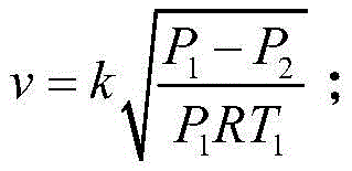
determining the gas flow velocity v of the electric control valve based on the pressure difference of two ends of the electric control valve, wherein the calculation formula is as follows:

wherein k is a preset coefficient;
obtaining the air outlet sectional area S of the pre-stored second air outlet valve0Determining the gas outlet radius S of the electric control valve controlled by the controller1The calculation formula is as follows:

wherein, P0Indicating the pressure at the first air-using end;
according to the determined gas outlet radius S of the electric control valve1And controlling the opening of the electric control valve.
Additional features and advantages of the invention will be set forth in the description which follows, and in part will be obvious from the description, or may be learned by practice of the invention. The objectives and other advantages of the invention will be realized and attained by the structure particularly pointed out in the written description and claims hereof as well as the appended drawings.
The technical solution of the present invention is further described in detail by the accompanying drawings and embodiments.
Drawings
The accompanying drawings, which are included to provide a further understanding of the invention and are incorporated in and constitute a part of this specification, illustrate embodiments of the invention and together with the description serve to explain the principles of the invention and not to limit the invention. In the drawings:
FIG. 1 is a schematic view of a modular nitrogen generator according to an embodiment of the present invention;
FIG. 2 is a schematic view of a replacement mechanism according to an embodiment of the present invention;
FIG. 3 is a schematic view of yet another modular nitrogen generator in accordance with an embodiment of the present invention;
FIG. 4 is an enlarged view taken at A in FIG. 3;
FIG. 5 is an enlarged view of FIG. 3 at B;
fig. 6 is a schematic view of a modular nitrogen generator according to an embodiment of the present invention.
In the figure:
1. a housing; 2. a gas adsorption tank; 3. a deformation member; 4. a compressed gas inlet end; 21. a first gas adsorption chamber; 22. a second gas adsorption chamber; 31. a first intake valve; 32. a first gas outlet valve; 33. a second gas outlet valve; 34. a second intake valve; 35. a third gas outlet valve; 36. a fourth gas outlet valve; 37. an electrically controlled valve; 38. a three-way electric control valve; 41. a mechanism is replaced; 42. a modular adsorption screen; 43. a sound absorbing mechanism; 44. a damping mechanism; 51. a communicating portion; 52. a rubber body; 53. accommodating grooves; 54. a protrusion; 55. a first groove; 80. a controller; 81. a first oxygen sensor; 82. a second oxygen sensor; 83. a third oxygen sensor; 84. a fourth oxygen sensor; 85. a first air pressure sensor; 86. a second air pressure sensor; 411. replacing the window; 412. sealing the cabin door; 431. a sound absorbing layer; 432. a sound absorbing groove; 441. a damper plate; 442. a guide post; 443. a damping spring; 444. a second groove; 445. a guide cylinder.
Detailed Description
The preferred embodiments of the present invention will be described in conjunction with the accompanying drawings, and it will be understood that they are described herein for the purpose of illustration and explanation and not limitation.
An embodiment of the present invention provides a modular nitrogen generator, as shown in fig. 1, including:
the number of the housings 1 is such that,
a gas adsorption tank 2 disposed in the housing 1;
a first gas adsorption chamber 21 and a second gas adsorption chamber 22, which are provided in the gas adsorption tank 2;
and a deforming member 3 disposed between the first gas adsorbing chamber 21 and the second gas adsorbing chamber 22.
The working principle and the beneficial effects of the technical scheme are as follows:
compressed air is alternately introduced into the first gas adsorption cavity 21 and the second gas adsorption cavity 22, and oxygen in the compressed air is adsorbed by the molecular sieves in the first gas adsorption cavity 21 and the second gas adsorption cavity 22, so that nitrogen is produced; when compressed air is introduced into the first gas adsorption cavity 21, pressure from the first gas adsorption cavity 21 to the second gas adsorption cavity 22 is generated on the deformation component 3 between the first gas adsorption cavity 21 and the second gas adsorption cavity 22 due to the pressure difference between the first gas adsorption cavity 21 and the second gas adsorption cavity 22, the deformation component 3 deforms under the action of the pressure to extrude the second gas adsorption cavity 22, so that the space of a first gas adsorption space in adsorption operation is increased, the yield of nitrogen is improved, and when equipment with the same yield is adopted, the size of the modular nitrogen making machine is reduced, the cost of the equipment is reduced, and the modular nitrogen making machine is convenient to install, store and transport.
According to the modular nitrogen making machine, the change of the dynamic adsorption space is realized through the deformation part 3, the nitrogen yield is improved, and when the equipment with the same yield is adopted, the size of the modular nitrogen making machine is reduced, so that the cost of the equipment is reduced, and the installation, storage and transportation are convenient.
In one embodiment, as shown in fig. 6, a first pipeline and a second pipeline are respectively arranged at two ends of the first gas adsorption cavity 21; the first pipeline is respectively connected with a first air inlet valve 31 and a first air outlet valve 32; the second pipeline is connected with a second air outlet valve 33; one end of the first air inlet valve 31 far away from the first pipeline is connected with a compressed air inlet end; one end of the second air outlet valve 33 far away from the second pipeline is connected with a first air end;
a third pipeline and a fourth pipeline are respectively arranged at two ends of the second gas adsorption cavity 22; the third pipeline is respectively connected with a second air inlet valve 34 and a third air outlet valve 35; the fourth pipeline is connected with a fourth air outlet valve 36; one end of the second air inlet valve 34 far away from the third pipeline is connected with a compressed air inlet end; the end of the fourth outlet valve 36 remote from the fourth line is connected to the first gas end.
The working principle and the beneficial effects of the technical scheme are as follows:
when the first gas adsorption cavity 21 adsorbs and produces nitrogen gas, introducing compressed air from the compressed gas inlet end connected with the first inlet valve 31 of the first pipeline, and discharging the produced nitrogen gas from the second outlet valve 33 of the second pipeline; during the desorption phase, the adsorbed oxygen-enriched gas is discharged through a first gas outlet valve 32 of the first line;
when the second gas adsorption cavity 22 adsorbs and produces nitrogen gas, compressed air is introduced from the compressed gas inlet end connected with the second inlet valve 34 of the third pipeline, and produced nitrogen gas is discharged from the fourth outlet valve 36 of the fourth pipeline; in the desorption stage, the adsorbed oxygen-enriched gas is discharged through a third gas outlet valve 35 of the third pipeline;
the pipeline for discharging the oxygen-enriched gas during desorption and the compressed gas inlet pipeline during adsorption are reused, so that the arrangement of the pipelines is reduced, and the cost is reduced; and the reuse of the pipeline for discharging the oxygen-enriched gas and the gas outlet pipeline for nitrogen during desorption is avoided, so that the oxygen-enriched gas is remained in the pipeline, and the influence on the next adsorption nitrogen production is avoided.
In one embodiment, a plurality of replacement mechanisms 41 for replacing modular adsorption screens 42 are provided outside the gas adsorption tanks 2,
as shown in fig. 2, the replacement mechanism 41 includes:
a replacing window 411, wherein a step is arranged at one end of the replacing window 411 close to the inner wall of the first gas adsorption cavity 21 or the inner wall of the second gas adsorption cavity 22, and a clamping groove capable of accommodating one end of the modular adsorption sieve 42 is arranged at the position of the inner wall of the first gas adsorption cavity 21 or the inner wall of the second gas adsorption cavity 22 corresponding to the replacing window 411;
a sealing hatch door 412 disposed on the replacement window 411;
the modular adsorbent screen 42 includes: a T-shaped body; the inside chamber that holds that sets up of T type body holds the chamber, holds the chamber and is used for holding the molecular sieve, evenly is provided with the sieve mesh that a plurality of apertures are less than the molecular sieve on T type body surface.
The working principle and the beneficial effects of the technical scheme are as follows:
after the molecular sieve is used for a long time, the adsorption effect is reduced, the molecular sieve needs to be replaced to ensure the adsorption effect, and the replacement efficiency is improved; the plurality of replacing mechanisms 41 are arranged on the outer side of the gas adsorption tank 2, when replacement is needed, only the sealing cabin door 412 needs to be opened, the modularized adsorption sieve 42 in the first gas adsorption cavity 21 or the second gas adsorption cavity 22 is removed, and a new modularized adsorption sieve 42 is replaced, so that the replacing method is simple and rapid; the modular adsorption sieve 42 is T-shaped, so that one end of the modular adsorption sieve is attached to a step of the replacement window 411, and the sealing performance is improved; the other end is arranged in a clamping groove on the side wall of the other side of the first gas adsorption cavity 21 or the second gas adsorption cavity 22; the modular adsorption sieve 42 is fixed in the first gas adsorption chamber 21 or the second gas adsorption chamber 22 through the clamping groove and the replacement window 411.
In one embodiment, as shown in fig. 3, a sound absorbing mechanism 43 is provided on the inner wall of the casing 1;
the sound absorbing mechanism 43 includes:
the sound absorption layer 431 is made of sound absorption cotton, and a plurality of sound absorption grooves 432 are uniformly arranged in an array mode on one side, close to the gas adsorption tank 2, of the sound absorption layer 431.
The working principle and the beneficial effects of the technical scheme are as follows:
the noise generated when the modular nitrogen making machine works is absorbed through the sound absorption layer 431, so that the working noise of the modular nitrogen making machine is reduced; the sound absorption groove 432 may reflect noise several times within the groove, thereby improving the noise reduction effect of the sound absorption layer 431.
In one embodiment, as shown in fig. 4, the deforming part 3 includes:
a rubber body 52;
a communicating portion 51 is provided between the first gas adsorption chamber 21 and the second gas adsorption chamber 22, and a receiving groove 53 is provided in the middle of the communicating portion 51; the accommodating groove 53 is provided in the rubber body 52;
a plurality of protrusions 54 are disposed on the edge of the rubber body 52, and a first groove 55 for accommodating the protrusions 54 is disposed on the inner wall of the accommodating groove 53.
The working principle and the beneficial effects of the technical scheme are as follows:
the rubber body 52 deforms under the action of pressure, and when the pressure of the first gas adsorption cavity 21 is greater than the pressure of the second gas adsorption cavity 22 (when the first gas adsorption cavity 21 adsorbs), the rubber body deforms towards the right side, so that the capacity of the first gas pressure cavity is increased; the change of dynamic adsorption space is realized through the rubber body 52, the yield of nitrogen is improved, and when the equipment with the same yield is adopted, the size of the modular nitrogen making machine is reduced, so that the cost of the equipment is reduced, and the installation, storage and transportation are convenient. The cooperation of the protrusion 54 and the first groove 55 achieves the fixation and sealing of the rubber body 52.
In one embodiment, a plurality of damper mechanisms 44 are provided between the gas adsorption tank 2 and the inner wall of the housing 1;
as shown in fig. 5, the damper mechanism 44 includes: damper plate 441, at least one guide post 442, and at least one damper spring 443; the damping plate 441 is arranged close to the outer surface of the gas adsorption tank 2; the shape of the surface of the damper plate 441 on the side close to the outer surface of the gas adsorption tank 2 is adapted to the shape of the outer surface of the gas adsorption tank 2; one end of the guide post 442 is fixedly connected with the damping plate 441, and the other end is slidably connected with the inner wall of the shell 1; one end of the damping spring 443 is fixedly connected with the damping plate 441, and the other end of the damping spring 443 is fixedly connected with the inner wall of the shell 1; the damper plate 441 is provided with a second groove 444 and a guide post body 445 at a position fixedly connected with the damper spring 443 and at a position fixedly connected with the damper spring 443 on the inner wall of the housing 1, respectively; the guide post 445 is disposed at the middle of the second groove 444; the damper spring 443 is fitted over the guide cylinder 445 and disposed in the second recess 444.
The working principle and the beneficial effects of the technical scheme are as follows:
the plurality of damper mechanisms 44 restrict the outside of the gas canister 2 in the vertical and horizontal directions, thereby reducing noise generated from the gas canister 2 due to vibration. The damping mechanism 44 is slidably connected with the housing 1 through the guide column 442, so that the stress direction of the damping spring 443 is ensured, the stress direction of the damping spring 443 is limited in the axial direction, and the service life of the damping spring 443 is prolonged; the damper spring 443 is further restricted from moving in the axial direction by the guide post body 445.
In one embodiment, a fifth pipeline is communicated between the second pipeline and the fourth pipeline, and an electrically controlled valve 37 is arranged in the middle of the fifth pipeline.
The working principle and the beneficial effects of the technical scheme are as follows:
when the second gas adsorption cavity 22 is in the desorption state, the first gas adsorption cavity 21 is in the adsorption state; the nitrogen produced in the first gas adsorption cavity 21 is used for purging the second gas adsorption cavity 22 through the fifth pipeline, so that the oxygen-enriched gas analyzed from the second gas adsorption cavity 22 can be discharged more easily, and the adsorption effect of the second gas adsorption cavity 22 at the next time is ensured. Similarly, the first gas adsorption chamber 21 may be purged with nitrogen gas produced in the second gas adsorption chamber 22. In addition, the deforming member 3 reduces the volume of the first gas adsorption chamber 21 or the second gas adsorption chamber 22 during desorption as compared with the original volume, thereby saving the amount of purge gas.
In one embodiment, the first outlet valve 32 and the third outlet valve 35 are both connected to one end of a three-way electrically controlled valve 38; the other two ends of the three-way electric control valve 38 are respectively communicated with the oxygen-enriched gas using end and the exhaust end.
The working principle and the beneficial effects of the technical scheme are as follows:
in the desorption stage, the desorbed gas is oxygen-enriched gas, and in the purging stage, the gas is mainly nitrogen; therefore, the three-way electric control valve 38 is adopted to realize gas shunting in the desorption stage; introducing the oxygen-enriched gas into the gas end of the oxygen-enriched gas; introducing a purge gas, predominantly nitrogen, into the exhaust end; the auxiliary product oxygen-enriched gas of the modular nitrogen generator is effectively utilized.
In one embodiment, as shown in fig. 6, the modular nitrogen generator further comprises:
a first oxygen sensor 81 disposed in the first pipe;
a second oxygen sensor 82 disposed in the second conduit;
a third oxygen sensor 83 arranged in the third pipeline;
a fourth oxygen sensor 84 disposed in the fourth conduit;
a first air pressure sensor 85 provided in the first gas adsorption chamber 21;
a second gas pressure sensor 86 disposed in the second gas adsorption chamber 22;
the controller 80 is arranged outside the shell 1 and is respectively electrically connected with the first oxygen sensor 81, the second oxygen sensor 82, the third oxygen sensor 83, the fourth oxygen sensor 84, the first air inlet valve 31, the second air inlet valve 34, the first air outlet valve 32, the third air outlet valve 35, the second air outlet valve 33, the fourth air outlet valve 36, the electric control valve 37, the three-way electric control valve 38, the first air pressure sensor 85 and the second air pressure sensor 86;
the controller 80 performs operations including:
controlling the first air inlet valve 31 to open to introduce compressed air into the first gas adsorption cavity 21, detecting a first pressure value in the first gas adsorption cavity 21 through the first air pressure sensor 85, closing the first air inlet valve 31 and starting timing when the first pressure value reaches a preset first standard pressure, and opening the second air outlet valve 33 to convey nitrogen to the first air end when the preset first time is reached;
when the first gas inlet valve 31 is opened, the second gas inlet valve 34, the third gas outlet valve 35 and the fourth gas outlet valve 36 of the second gas adsorption cavity 22 are controlled to be closed, so that desorption of the second gas adsorption cavity 22 is realized; when the second gas outlet valve 33 is opened, the electric control valve 37 and the third gas outlet valve 35 on the fifth pipeline are synchronously opened, the three-way electric control valve 38 is switched to be communicated with the exhaust end, and the second gas adsorption cavity 22 is purged by using nitrogen;
after the second gas outlet valve 33 is controlled to be opened to convey nitrogen to the first gas end, when the pressure in the first gas adsorption cavity 21 is reduced to a preset second standard pressure, the second gas outlet valve 33 is closed, and the first gas outlet valve 32 is opened to realize desorption of the first gas adsorption cavity 21;
when the first air outlet valve 32 is opened, the second air inlet valve 34 is controlled to be opened, the third air outlet valve 35 is controlled to be closed, so the electric control valve 37 is closed, the fourth air outlet valve 36 is closed, compressed air is introduced into the second gas adsorption cavity 22, a second pressure value in the second gas adsorption cavity 22 is detected through a second air pressure sensor 86, when the second pressure value reaches a preset first standard pressure, the second air inlet valve 34 is closed and timing is started, and when a preset first time is reached, the fourth air outlet valve 36 is opened to convey nitrogen to the first air end; opening the fourth gas outlet valve 36, opening the electric control valve 37 and the first gas outlet valve 32, switching the three-way electric control valve 38 to be communicated with the exhaust end, and purging the first gas adsorption cavity 21 by using nitrogen;
during desorption of the second gas adsorption chamber 22, detecting a third oxygen content in the third pipeline by the third oxygen sensor 83; when the third oxygen content is greater than the preset first standard oxygen content, the three-way electric control valve 38 is controlled to be communicated with the oxygen-enriched gas using end; when the third oxygen content is less than or equal to the preset first standard oxygen content, the three-way electric control valve 38 is controlled to be communicated with the exhaust end;
during desorption of the second gas adsorption chamber 22, a first oxygen content in the first pipe is detected by the first oxygen sensor 81; when the first oxygen content is larger than the preset first standard oxygen content, the three-way electric control valve 38 is controlled to be communicated with the oxygen-enriched gas using end; when the first oxygen content is less than or equal to the preset first standard oxygen content, the three-way electronic control valve 38 is controlled to be communicated with the exhaust end;
when the second air outlet valve 33 is opened, the second oxygen content in the second pipeline is detected through the second oxygen sensor 82, and when the second oxygen content is larger than the preset second standard oxygen content, an alarm is output;
when the fourth air outlet valve 36 is opened, the fourth oxygen content in the fourth pipeline is detected through the fourth oxygen sensor 84, and when the fourth oxygen content is larger than the preset second standard oxygen content, an alarm is output.
The working principle and the beneficial effects of the technical scheme are as follows:
the controller 80 monitors data in the working process of the modular nitrogen generator according to the first oxygen sensor 81, the second oxygen sensor 82, the third oxygen sensor 83, the fourth oxygen sensor 84, the first air pressure sensor 85 and the second air pressure sensor 86, and detects the quality of the produced nitrogen gas through the second oxygen sensor 82 and the fourth oxygen sensor 84 to realize quality control; in the analysis stage, the controller 80 tests the oxygen content of the desorbed gas through the first oxygen sensor 81 or the third oxygen sensor 83 to control the oxygen content in the oxygen-enriched gas, so as to ensure the quality of the oxygen-enriched gas used by the gas end of the oxygen-enriched gas.
In one embodiment, when the controller 80 opens the electrically controlled valve 37 to purge the second gas adsorption chamber 22, the controller 80 obtains a first pressure value detected by the first gas pressure sensor 85 in real time, the controller 80 obtains a second pressure value detected by the second gas pressure sensor 86 in real time, controls the opening degree of the electrically controlled valve 37 based on the first pressure value and the second pressure value,
the controller 80 controls the opening degree of the electric control valve 37 based on the first pressure value and the second pressure value, and specifically includes:
the first air pressure sensor 85 obtains the air pressure P in the first air adsorption cavity 211(ii) a The pressure P in the second gas adsorption chamber 22 is acquired by the second gas pressure sensor 862;
Determining the pressure P of the deformable member 31And P2Volume V of deformation cavity formed by deformation0(ii) a At this time, the actual volume of the first gas adsorption chamber 21 is V1+V0(ii) a The actual volume of the second gas adsorption chamber 22 is V2-V0;
Determination of the molecular weight n in the first gas adsorption Chamber 211The calculation formula is as follows:

wherein R is a constant, T1Is the thermodynamic temperature of the gas in the first gas adsorption chamber 21;
based on the pressure difference between the two ends of the electric control valve 37, the gas flow velocity v of the electric control valve 37 is determined, and the calculation formula is as follows:
wherein k is a preset coefficient;
the air outlet sectional area S of the second air outlet valve 33 stored in advance is acquired0Determining the gas-out radius S of the electric control valve 37 controlled by the controller 801The calculation formula is as follows:

wherein, P0Indicating the pressure at the first air-using end;
according to the determined gas outlet radius S of the electric control valve 371The opening degree of the electrically controlled valve 37 is controlled.
The working principle and the beneficial effects of the technical scheme are as follows:
when the nitrogen gas produced in the first gas adsorption cavity 21 is adopted to purge the second gas adsorption cavity 22, the controller 80 obtains a first pressure value and a second pressure value in real time, determines the deformation condition of the deformation component 3 according to the pressure difference at two ends of the deformation component 3, and mainly determines the volume of the deformation cavity formed by the deformation component 3; the deformation component 3 can be subjected to an experiment under different pressure differences to form a deformation cavity under an experimental environment, experimental data are obtained, and then the volume of the deformation cavity is obtained on the basis of the experimental data according to the pressure difference between the first pressure value and the second pressure value. The opening of the electromagnetic valve is adjusted in real time through the detected pressure difference of the controller 80, so that the nitrogen consumption during purging is saved while the purging effect is ensured. Similarly, when the first gas adsorption cavity 21 is purged by using the nitrogen gas produced in the second gas adsorption cavity 22, the opening degree of the electromagnetic valve may be controlled according to the first pressure value and the second pressure value; and then the nitrogen consumption when sweeping has been practiced thrift in the effect of guaranteeing to sweep. Wherein R is a thermodynamic constant, and for any ideal gas, R is constant and is about 8.31441 + -0.00026J/(mol.K); k is a correction coefficient obtained by the Bernoulli equation according to practical application, and is an empirical value obtained through a large number of experiments.
It will be apparent to those skilled in the art that various changes and modifications may be made in the present invention without departing from the spirit and scope of the invention. Thus, if such modifications and variations of the present invention fall within the scope of the claims of the present invention and their equivalents, the present invention is also intended to include such modifications and variations.
Claims (10)
1. A modular nitrogen generator, comprising:
a shell body (1) is arranged in the shell body,
a gas adsorption tank (2) disposed in the housing (1);
a first gas adsorption chamber (21) and a second gas adsorption chamber (22) disposed in the gas adsorption tank (2);
a deformation member (3) disposed between the first gas adsorption chamber (21) and the second gas adsorption chamber (22).
2. Modular nitrogen generator as in claim 1, characterized in that at both ends of said first gas adsorption chamber (21) there are provided a first and a second line, respectively; the first pipeline is respectively connected with a first air inlet valve (31) and a first air outlet valve (32); the second pipeline is connected with a second air outlet valve (33); one end, far away from the first pipeline, of the first air inlet valve (31) is connected with a compressed air inlet end; one end of the second air outlet valve (33) far away from the second pipeline is connected with a first air end;
a third pipeline and a fourth pipeline are respectively arranged at two ends of the second gas adsorption cavity (22); the third pipeline is respectively connected with a second air inlet valve (34) and a third air outlet valve (35); the fourth pipeline is connected with a fourth air outlet valve (36); one end of the second air inlet valve (34) far away from the third pipeline is connected with a compressed air inlet end; and one end of the fourth air outlet valve (36) far away from the fourth pipeline is connected with a first air end.
3. Modular nitrogen generator according to claim 1, characterized in that outside the gas adsorption tank (2) a plurality of replacement mechanisms (41) for replacing modular adsorption sieves (42) are provided,
the replacement mechanism (41) includes:
a replacing window (411), wherein a step is arranged at one end of the replacing window (411) close to the inner wall of the first gas adsorption cavity (21) or the inner wall of the second gas adsorption cavity (22), and a clamping groove capable of accommodating one end of the modularized adsorption sieve (42) is arranged at the position, corresponding to the replacing window (411), of the inner wall of the first gas adsorption cavity (21) or the inner wall of the second gas adsorption cavity (22);
a sealing hatch (412) provided on the replacement window (411);
the modular adsorbent screen (42) comprises: a T-shaped body; the inside chamber that holds that sets up of T type body, it is used for holding the molecular sieve to hold the chamber T type body surface evenly is provided with a plurality of apertures and is less than the sieve mesh of molecular sieve.
4. Modular nitrogen generator as in claim 1, characterized in that on the inner wall of said casing (1) there are provided sound absorbing means (43);
the sound absorbing mechanism (43) includes:
inhale sound layer (431) that the sound cotton was made, sound layer (431) are close to one side of gas adsorption tank (2) sets up even array and is provided with a plurality of sound absorption grooves (432).
5. Modular nitrogen generator as claimed in claim 1, characterized in that said deformation means (3) comprise:
a rubber body (52);
a communicating part (51) is arranged between the first gas adsorption cavity (21) and the second gas adsorption cavity (22), and an accommodating groove (53) is arranged in the middle of the communicating part (51); the accommodating groove (53) is internally provided with the rubber body (52);
a plurality of protrusions (54) are arranged on the edge of the rubber body (52), and first grooves (55) capable of accommodating the protrusions (54) are arranged on the inner wall positions corresponding to the accommodating grooves (53).
6. Modular nitrogen generator as claimed in claim 1, characterized in that a plurality of shock-absorbing mechanisms (44) are provided between said gas adsorption tank (2) and the inner wall of said housing (1);
the shock absorbing mechanism (44) includes: a damper plate (441), at least one guide post (442), and at least one damper spring (443); the damping plate (441) is arranged close to the outer surface of the gas adsorption tank (2); the shape of the surface of the damping plate (441) on the side close to the outer surface of the gas adsorption tank (2) is adapted to the shape of the outer surface of the gas adsorption tank (2); one end of the guide post (442) is fixedly connected with the damping plate (441), and the other end of the guide post is slidably connected with the inner wall of the shell (1); one end of the damping spring (443) is fixedly connected with the damping plate (441), and the other end of the damping spring is fixedly connected with the inner wall of the shell (1); the damping plate (441) is provided with a second groove (444) and a guide post body (445) at the position fixedly connected with the damping spring (443) and the inner wall of the shell (1) is provided with the position fixedly connected with the damping spring (443), respectively; the guide pillar body (445) is arranged in the middle of the second groove (444); the shock absorption spring (443) is sleeved on the guide cylinder body (445) and arranged in the second groove (444).
7. Modular nitrogen generator as in claim 2, characterized in that between the second and fourth line there is a fifth line, in the middle of which there is an electrically controlled valve (37).
8. Modular nitrogen generator as in claim 7, characterized in that said first outlet valve (32) and said third outlet valve (35) are connected to one end of a three-way electric control valve (38); the other two ends of the three-way electric control valve (38) are respectively communicated with the oxygen-enriched gas using end and the exhaust end.
9. The modular nitrogen generator as recited in claim 8, further comprising:
a first oxygen sensor (81) disposed within the first conduit;
a second oxygen sensor (82) disposed within the second conduit;
a third oxygen sensor (83) arranged in the third pipeline;
a fourth oxygen sensor (84) disposed within the fourth conduit;
a first gas pressure sensor (85) disposed within the first gas adsorption chamber (21);
a second gas pressure sensor (86) disposed within the second gas adsorption chamber (22);
the controller (80) is arranged outside the shell (1) and is respectively electrically connected with the first oxygen sensor (81), the second oxygen sensor (82), the third oxygen sensor (83), the fourth oxygen sensor (84), the first air inlet valve (31), the second air inlet valve (34), the first air outlet valve (32), the third air outlet valve (35), the second air outlet valve (33), the fourth air outlet valve (36), the electric control valve (37), the three-way electric control valve (38), the first air pressure sensor (85) and the second air pressure sensor (86);
the controller (80) performs operations comprising:
detecting a fourth oxygen content within the fourth pipeline by the fourth oxygen sensor (84);
controlling the first air inlet valve (31) to be opened to introduce compressed air into the first gas adsorption cavity (21), detecting a first pressure value in the first gas adsorption cavity (21) through the first air pressure sensor (85), closing the first air inlet valve (31) and starting timing when the first pressure value reaches a preset first standard pressure, and opening the second air outlet valve (33) to convey nitrogen to the first air end when a preset first time is reached;
controlling the second gas inlet valve (34) of the second gas adsorption cavity (22) to be closed, the third gas outlet valve (35) to be opened and the fourth gas outlet valve (36) to be closed while the first gas inlet valve (31) is opened, so as to realize desorption of the second gas adsorption cavity (22); when the second gas outlet valve (33) is opened, the electric control valve (37) and the third gas outlet valve (35) on the fifth pipeline are synchronously opened, the three-way electric control valve (38) is switched to be communicated with the gas exhaust end, and the second gas adsorption cavity (22) is purged by using nitrogen;
after the second gas outlet valve (33) is controlled to be opened to convey nitrogen to the first gas end, when the pressure in the first gas adsorption cavity (21) is reduced to a preset second standard pressure, the second gas outlet valve (33) is closed, the first gas outlet valve (32) is opened, and desorption of the first gas adsorption cavity (21) is realized;
when the first air outlet valve (32) is opened, the second air inlet valve (34) is controlled to be opened, the third air outlet valve (35) is closed, the electric control valve (37) is closed, the fourth air outlet valve (36) is closed, compressed air is introduced into the second gas adsorption cavity (22), a second pressure value in the second gas adsorption cavity (22) is detected through the second air pressure sensor (86), when the second pressure value reaches a preset first standard pressure, the second air inlet valve (34) is closed and timing is started, and when a preset first time is reached, the fourth air outlet valve (36) is opened to convey nitrogen to the first gas using end; opening the fourth gas outlet valve (36), simultaneously opening the electric control valve (37) and the first gas outlet valve (32), switching the three-way electric control valve (38) to be communicated with the exhaust end, and purging the first gas adsorption cavity (21) by using nitrogen;
during the desorption process of the second gas adsorption cavity (22), detecting the third oxygen content in the third pipeline through the third oxygen sensor (83); when the third oxygen content is larger than a preset first standard oxygen content, controlling the three-way electric control valve (38) to be communicated with the oxygen-enriched gas using end; when the third oxygen content is less than or equal to a preset first standard oxygen content, controlling the three-way electric control valve (38) to be communicated with the exhaust end;
-detecting a first oxygen content in said first conduit by said first oxygen sensor (81) during desorption of said second gas adsorption chamber (22); when the first oxygen content is larger than a preset first standard oxygen content, controlling the three-way electric control valve (38) to be communicated with the oxygen-enriched gas using end; when the first oxygen content is less than or equal to a preset first standard oxygen content, controlling the three-way electric control valve (38) to be communicated with the exhaust end;
when the second air outlet valve (33) is opened, detecting the second oxygen content in the second pipeline through the second oxygen sensor (82), and outputting an alarm when the second oxygen content is larger than a preset second standard oxygen content;
when the fourth air outlet valve (36) is opened, the fourth oxygen content in the fourth pipeline is detected through the fourth oxygen sensor (84), and when the fourth oxygen content is larger than the preset second standard oxygen content, an alarm is output.
10. The modular nitrogen generator as claimed in claim 9, wherein when the controller (80) opens the electrically controlled valve (37) to purge the second gas adsorption chamber (22), the controller (80) acquires the first pressure value detected by the first gas pressure sensor (85) in real time, the controller (80) acquires the second pressure value detected by the second gas pressure sensor (86) in real time, the opening degree of the electrically controlled valve (37) is controlled based on the first pressure value and the second pressure value,
the controller (80) controls the opening degree of the electric control valve (37) based on the first pressure value and the second pressure value, and specifically comprises:
acquiring the air pressure P in the first gas adsorption cavity (21) through the first air pressure sensor (85)1(ii) a Acquiring the pressure P in the second gas adsorption cavity (22) through the second gas pressure sensor (86)2;
Determining the pressure P of the deformation element (3)1And P2Volume V of deformation cavity formed by deformation0(ii) a At this time, the actual volume of the first gas adsorption chamber (21) is V1+V0(ii) a The actual volume of the second gas adsorption cavity (22) is V2-V0;
Determining the molecular weight n within the first gas adsorption chamber (21)1The calculation formula is as follows:

wherein R is a constant, T1Is the thermodynamic temperature of the gas in the first gas adsorption chamber (21);
determining the gas flow velocity v of the electric control valve (37) based on the pressure difference between the two ends of the electric control valve (37), wherein the calculation formula is as follows:

wherein k is a preset coefficient;
obtaining the air outlet sectional area S pre-stored with the second air outlet valve (33)0Determining the gas outlet radius S of the electric control valve (37) controlled by the controller (80)1The calculation formula is as follows:

wherein, P0Representing the pressure of the first air-using end;
according to the determined gas outlet radius S of the electric control valve (37)1And controlling the opening degree of the electric control valve (37).
Priority Applications (1)
| Application Number | Priority Date | Filing Date | Title |
|---|---|---|---|
| CN202010692212.6A CN111825065B (en) | 2020-07-17 | 2020-07-17 | Modular nitrogen making machine |
Applications Claiming Priority (1)
| Application Number | Priority Date | Filing Date | Title |
|---|---|---|---|
| CN202010692212.6A CN111825065B (en) | 2020-07-17 | 2020-07-17 | Modular nitrogen making machine |
Publications (2)
| Publication Number | Publication Date |
|---|---|
| CN111825065A true CN111825065A (en) | 2020-10-27 |
| CN111825065B CN111825065B (en) | 2021-05-28 |
Family
ID=72923484
Family Applications (1)
| Application Number | Title | Priority Date | Filing Date |
|---|---|---|---|
| CN202010692212.6A Active CN111825065B (en) | 2020-07-17 | 2020-07-17 | Modular nitrogen making machine |
Country Status (1)
| Country | Link |
|---|---|
| CN (1) | CN111825065B (en) |
Cited By (2)
| Publication number | Priority date | Publication date | Assignee | Title |
|---|---|---|---|---|
| CN113509817A (en) * | 2021-05-25 | 2021-10-19 | 江阴洋田气体设备有限公司 | Pressure swing adsorption nitrogen making process and nitrogen making machine |
| CN113877373A (en) * | 2021-09-14 | 2022-01-04 | 浙江远大空分设备有限公司 | Modular nitrogen making machine |
Citations (10)
| Publication number | Priority date | Publication date | Assignee | Title |
|---|---|---|---|---|
| CN103620759A (en) * | 2011-07-01 | 2014-03-05 | 日本电气工程株式会社 | Tape application apparatus |
| CN204656290U (en) * | 2015-06-01 | 2015-09-23 | 西梅卡亚洲气体系统成都有限公司 | The swing adsorption nitrogen producing apparatus of a kind of adsorption tower and formation thereof |
| JP2017087101A (en) * | 2015-11-04 | 2017-05-25 | 新日鐵住金株式会社 | Gas separator |
| CN206867940U (en) * | 2017-05-17 | 2018-01-12 | 山东旭晟东阳新材料科技有限公司 | Adsorbing tower with molecular sieve |
| CN206940431U (en) * | 2017-07-10 | 2018-01-30 | 河北锐智纳米科技有限公司 | Carbon molecular sieve swing adsorption nitrogen producing apparatus |
| CN207498061U (en) * | 2017-11-02 | 2018-06-15 | 杭州富阳雷讯科技咨询服务有限公司 | One kind is used for the oxygen-enriched collection system of varying-voltage adsorption nitrogen machine emptying end gas |
| CN207726740U (en) * | 2017-11-02 | 2018-08-14 | 杭州富阳雷讯科技咨询服务有限公司 | A kind of equipment of making nitrogen efficient yield system |
| CN110180326A (en) * | 2019-05-06 | 2019-08-30 | 盖斯伊科技(苏州)有限公司 | A kind of nitrogen separation equipment |
| CN110203892A (en) * | 2019-07-03 | 2019-09-06 | 山东恒业石油新技术应用有限公司 | A kind of hi-temp hi-effective Quick-type THE PRESSURE SWING ADSORPTION NITROGEN GENERATING DEVICE and its method for preparing nitrogen |
| CN111217341A (en) * | 2020-03-26 | 2020-06-02 | 江苏轻跃气体科技有限公司 | PSA nitrogen production system process flow |
-
2020
- 2020-07-17 CN CN202010692212.6A patent/CN111825065B/en active Active
Patent Citations (10)
| Publication number | Priority date | Publication date | Assignee | Title |
|---|---|---|---|---|
| CN103620759A (en) * | 2011-07-01 | 2014-03-05 | 日本电气工程株式会社 | Tape application apparatus |
| CN204656290U (en) * | 2015-06-01 | 2015-09-23 | 西梅卡亚洲气体系统成都有限公司 | The swing adsorption nitrogen producing apparatus of a kind of adsorption tower and formation thereof |
| JP2017087101A (en) * | 2015-11-04 | 2017-05-25 | 新日鐵住金株式会社 | Gas separator |
| CN206867940U (en) * | 2017-05-17 | 2018-01-12 | 山东旭晟东阳新材料科技有限公司 | Adsorbing tower with molecular sieve |
| CN206940431U (en) * | 2017-07-10 | 2018-01-30 | 河北锐智纳米科技有限公司 | Carbon molecular sieve swing adsorption nitrogen producing apparatus |
| CN207498061U (en) * | 2017-11-02 | 2018-06-15 | 杭州富阳雷讯科技咨询服务有限公司 | One kind is used for the oxygen-enriched collection system of varying-voltage adsorption nitrogen machine emptying end gas |
| CN207726740U (en) * | 2017-11-02 | 2018-08-14 | 杭州富阳雷讯科技咨询服务有限公司 | A kind of equipment of making nitrogen efficient yield system |
| CN110180326A (en) * | 2019-05-06 | 2019-08-30 | 盖斯伊科技(苏州)有限公司 | A kind of nitrogen separation equipment |
| CN110203892A (en) * | 2019-07-03 | 2019-09-06 | 山东恒业石油新技术应用有限公司 | A kind of hi-temp hi-effective Quick-type THE PRESSURE SWING ADSORPTION NITROGEN GENERATING DEVICE and its method for preparing nitrogen |
| CN111217341A (en) * | 2020-03-26 | 2020-06-02 | 江苏轻跃气体科技有限公司 | PSA nitrogen production system process flow |
Cited By (3)
| Publication number | Priority date | Publication date | Assignee | Title |
|---|---|---|---|---|
| CN113509817A (en) * | 2021-05-25 | 2021-10-19 | 江阴洋田气体设备有限公司 | Pressure swing adsorption nitrogen making process and nitrogen making machine |
| CN113877373A (en) * | 2021-09-14 | 2022-01-04 | 浙江远大空分设备有限公司 | Modular nitrogen making machine |
| CN113877373B (en) * | 2021-09-14 | 2023-10-03 | 浙江凯斯泰克制造科技有限公司 | Modularized nitrogen making machine |
Also Published As
| Publication number | Publication date |
|---|---|
| CN111825065B (en) | 2021-05-28 |
Similar Documents
| Publication | Publication Date | Title |
|---|---|---|
| KR100346487B1 (en) | Pressure swing adsorption gas flow control method and system | |
| CN111825065B (en) | Modular nitrogen making machine | |
| JP4301452B2 (en) | Gas concentration method and apparatus | |
| EP1203610B1 (en) | Single bed pressure swing adsorption process | |
| US7651549B2 (en) | Pressure swing adsorption process with improved recovery of high-purity product | |
| JP5134704B2 (en) | Off-gas supply method | |
| US8529674B2 (en) | Pressure swing adsorption method and system with multiple-vessel beds | |
| US5882380A (en) | Pressure swing adsorption process with a single adsorbent bed | |
| EP1027915A2 (en) | Single bed pressure swing adsorption process and system | |
| NO179129B (en) | Method of separating gas mixtures | |
| EP1426094A1 (en) | Pressure swing adsorption system for gas separation | |
| US6146447A (en) | Oxygen generation process and system using single adsorber and single blower | |
| CN109052328A (en) | A kind of circulation oxygen generating plant | |
| KR100741307B1 (en) | The apparatus of oxygen concentration system | |
| JPH04227813A (en) | Improved control for pressure variable adsorption operation | |
| US5961694A (en) | Apparatus and process for the separation of gas mixtures by pressure swing adsorption | |
| US20070274845A1 (en) | Fluid Storage And Dispensing System | |
| JP2006511346A (en) | Gas concentrator | |
| KR101773437B1 (en) | Absorbing tower having complex absorption structure for oxygen generator | |
| KR101647017B1 (en) | Oxygen concentrating method and apparatus having condensate water removing function | |
| AU593993B2 (en) | Hydrostatic method employing psa vent gas pressure for vacuum regeneration | |
| JP2011251243A (en) | Gas separator | |
| US7297187B2 (en) | Gas separation apparatus | |
| CN107405563B (en) | Process for producing oxygen by VPSA | |
| JP3138067B2 (en) | Gas separation device |
Legal Events
| Date | Code | Title | Description |
|---|---|---|---|
| PB01 | Publication | ||
| PB01 | Publication | ||
| SE01 | Entry into force of request for substantive examination | ||
| SE01 | Entry into force of request for substantive examination | ||
| TA01 | Transfer of patent application right |
Effective date of registration: 20210422 Address after: 239000 in the east of Suchu Avenue, south of Zhoushan Road, west of Chuzhou Avenue and north of Wuhu Road, Chuzhou City, Anhui Province Applicant after: Chuzhou Guanggang Gas Co.,Ltd. Address before: 215000 North-east Floor of No.8 Factory Building, No.98 Hengshan Road, Suzhou High-tech Zone, Jiangsu Province Applicant before: GAISIYI TECHNOLOGY (SUZHOU) Co.,Ltd. |
|
| TA01 | Transfer of patent application right | ||
| GR01 | Patent grant | ||
| GR01 | Patent grant |