CN111805393B - Automatic change burnishing device - Google Patents

Automatic change burnishing device Download PDF

Info

Publication number
CN111805393B
CN111805393B CN202010534077.2A CN202010534077A CN111805393B CN 111805393 B CN111805393 B CN 111805393B CN 202010534077 A CN202010534077 A CN 202010534077A CN 111805393 B CN111805393 B CN 111805393B
Authority
CN
China
Prior art keywords
limiting
movable plate
groove
connecting rod
movable
Prior art date
Legal status (The legal status is an assumption and is not a legal conclusion. Google has not performed a legal analysis and makes no representation as to the accuracy of the status listed.)
Active
Application number
CN202010534077.2A
Other languages
Chinese (zh)
Other versions
CN111805393A (en
Inventor
王正才
Current Assignee (The listed assignees may be inaccurate. Google has not performed a legal analysis and makes no representation or warranty as to the accuracy of the list.)
Zhejiang Qianfang Baiji Electric Power Equipment Co ltd
Original Assignee
Ningbo Polytechnic
Priority date (The priority date is an assumption and is not a legal conclusion. Google has not performed a legal analysis and makes no representation as to the accuracy of the date listed.)
Filing date
Publication date
Application filed by Ningbo Polytechnic filed Critical Ningbo Polytechnic
Priority to CN202010534077.2A priority Critical patent/CN111805393B/en
Publication of CN111805393A publication Critical patent/CN111805393A/en
Application granted granted Critical
Publication of CN111805393B publication Critical patent/CN111805393B/en
Active legal-status Critical Current
Anticipated expiration legal-status Critical

Links

Images

Classifications

    • B—PERFORMING OPERATIONS; TRANSPORTING
    • B24—GRINDING; POLISHING
    • B24B—MACHINES, DEVICES, OR PROCESSES FOR GRINDING OR POLISHING; DRESSING OR CONDITIONING OF ABRADING SURFACES; FEEDING OF GRINDING, POLISHING, OR LAPPING AGENTS
    • B24B29/00—Machines or devices for polishing surfaces on work by means of tools made of soft or flexible material with or without the application of solid or liquid polishing agents
    • B—PERFORMING OPERATIONS; TRANSPORTING
    • B24—GRINDING; POLISHING
    • B24B—MACHINES, DEVICES, OR PROCESSES FOR GRINDING OR POLISHING; DRESSING OR CONDITIONING OF ABRADING SURFACES; FEEDING OF GRINDING, POLISHING, OR LAPPING AGENTS
    • B24B41/00—Component parts such as frames, beds, carriages, headstocks
    • B24B41/02—Frames; Beds; Carriages
    • B—PERFORMING OPERATIONS; TRANSPORTING
    • B24—GRINDING; POLISHING
    • B24B—MACHINES, DEVICES, OR PROCESSES FOR GRINDING OR POLISHING; DRESSING OR CONDITIONING OF ABRADING SURFACES; FEEDING OF GRINDING, POLISHING, OR LAPPING AGENTS
    • B24B41/00—Component parts such as frames, beds, carriages, headstocks
    • B24B41/04—Headstocks; Working-spindles; Features relating thereto
    • B—PERFORMING OPERATIONS; TRANSPORTING
    • B24—GRINDING; POLISHING
    • B24B—MACHINES, DEVICES, OR PROCESSES FOR GRINDING OR POLISHING; DRESSING OR CONDITIONING OF ABRADING SURFACES; FEEDING OF GRINDING, POLISHING, OR LAPPING AGENTS
    • B24B41/00—Component parts such as frames, beds, carriages, headstocks
    • B24B41/06—Work supports, e.g. adjustable steadies
    • B—PERFORMING OPERATIONS; TRANSPORTING
    • B24—GRINDING; POLISHING
    • B24B—MACHINES, DEVICES, OR PROCESSES FOR GRINDING OR POLISHING; DRESSING OR CONDITIONING OF ABRADING SURFACES; FEEDING OF GRINDING, POLISHING, OR LAPPING AGENTS
    • B24B47/00—Drives or gearings; Equipment therefor
    • B24B47/22—Equipment for exact control of the position of the grinding tool or work at the start of the grinding operation

Landscapes

  • Engineering & Computer Science (AREA)
  • Mechanical Engineering (AREA)
  • Finish Polishing, Edge Sharpening, And Grinding By Specific Grinding Devices (AREA)

Abstract

本发明公开一种自动化抛光装置,包括工作台、顶起机构、活动板调节机构、可移动废屑清理机构以及升降调节机构,所述工作台的内部开设有安装槽,所述工作台的内部设置有顶起机构,所述顶起机构的一端安装有主三爪卡盘,所述活动板上设置有可移动废屑清理机构,所述活动板上表面设置有安装架,所述电机的运作端固定有副三爪卡盘,所述工作台的上表面一侧设置有升降调节机构,所述升降调节机构上安装有抛光电机,所述抛光电机上安装有抛光轮,所述抛光轮的正下方设置有主三爪卡盘,根据需要进行抛光的物件形状,选择相应的三爪卡盘进行固定,对圆柱状的物件进行抛光处理的时候,通过副三爪卡盘对物件进行加持固定。
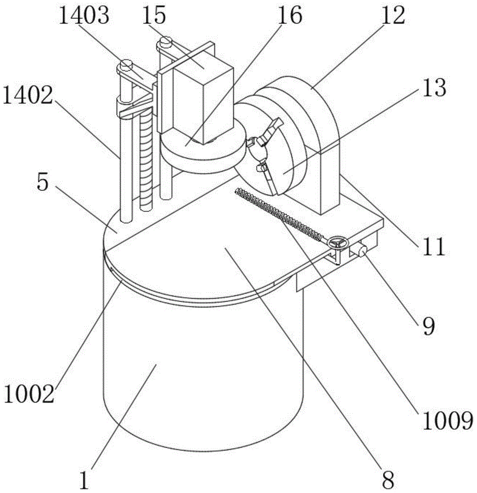
Figure 202010534077

The invention discloses an automatic polishing device, comprising a worktable, a jacking mechanism, a movable plate adjusting mechanism, a movable waste cleaning mechanism and a lifting adjusting mechanism. An installation groove is opened inside the worktable, and an interior of the worktable is provided with an installation groove. A jack-up mechanism is provided, one end of the jack-up mechanism is installed with a main three-jaw chuck, a movable waste cleaning mechanism is arranged on the movable plate, a mounting frame is arranged on the upper surface of the movable plate, and the motor is An auxiliary three-jaw chuck is fixed at the operating end, a lifting adjustment mechanism is arranged on one side of the upper surface of the worktable, a polishing motor is installed on the lifting adjustment mechanism, a polishing wheel is installed on the polishing motor, and the polishing wheel is installed There is a main three-jaw chuck directly below the surface. According to the shape of the object to be polished, select the corresponding three-jaw chuck to fix it. When polishing a cylindrical object, use the auxiliary three-jaw chuck to support the object. fixed.

Figure 202010534077

Description

Automatic change burnishing device
Technical Field
The invention belongs to the technical field of mechanical polishing, and particularly relates to an automatic polishing device.
Background
Polishing refers to a processing method for reducing the roughness of the surface of a workpiece by using mechanical, chemical or electrochemical actions to obtain a bright and flat surface, and is a modification processing of the surface of the workpiece by using a polishing tool and abrasive particles or other polishing media.
Polishing does not improve the dimensional accuracy or geometric accuracy of a workpiece, but aims to obtain a smooth surface or specular gloss, and sometimes also aims to eliminate gloss, and usually uses a polishing wheel as a polishing tool, the polishing wheel is generally made of multiple layers of canvas, felt or leather, the two sides of the polishing wheel are clamped by metal circular plates, and the rim of the polishing wheel is coated with a polishing agent formed by uniformly mixing micro-powder abrasive, grease and the like.
The prior polishing device has the following defects:
1. different mounting positions cannot be selected for polishing according to different shapes of the objects to be polished;
2. after the objects to be polished with different sizes are limited, the position of the limiting mechanism is inconvenient to adjust; 3. it is inconvenient to collect the waste generated by polishing.
Disclosure of Invention
To solve the problems set forth in the background art described above. The invention provides an automatic polishing device.
In order to achieve the purpose, the invention provides the following technical scheme: an automatic polishing device comprises a workbench, a jacking mechanism, a movable plate adjusting mechanism, a movable scrap cleaning mechanism and a lifting adjusting mechanism, wherein a mounting groove is formed in the workbench, the jacking mechanism is arranged in the workbench, a main three-jaw chuck is installed at one end of the jacking mechanism, two groups of support frames are arranged on the side surface of the workbench, a clamping groove and a limiting groove are formed in one group of the support frames, the movable plate is movably installed on the workbench, the movable plate adjusting mechanism is arranged between the workbench and the movable plate, the movable scrap cleaning mechanism is arranged on the movable plate, a mounting frame is arranged on the upper surface of the movable plate, a motor is installed on the mounting frame, an auxiliary three-jaw chuck is fixed at the operating end of the motor, the lifting adjusting mechanism is arranged on one side of the upper surface of the workbench, and a polishing motor is installed on the lifting adjusting mechanism, and a polishing wheel is arranged on the polishing motor, and a main three-jaw chuck is arranged right below the polishing wheel.
As a further improvement of the technical scheme, the worktable and the two groups of the supporting frames are of an integrated structure, two groups of limiting grooves are formed in the two groups of the supporting frames, and clamping grooves are formed between the two groups of the limiting grooves.
As a further improvement of the above technical scheme, the jacking mechanism comprises an electric telescopic rod, a supporting table and three supporting rods, the electric telescopic rod is installed in the mounting groove formed in the workbench, the supporting table is fixedly connected to one end of the electric telescopic rod, the three supporting rods are arranged on the supporting table at equal angles, and one ends of the supporting rods penetrate through holes formed in the workbench and are fixed to the bottom end of the main three-jaw chuck.
As a further improvement of the technical scheme, the movable plate adjusting mechanism comprises a first servo motor, an adjusting block and a limiting connecting rod, the first servo motor is fixedly installed between the two groups of supporting frames, the adjusting block and the limiting connecting rod are arranged below the movable plate, a screw rod arranged on the first servo motor is in threaded connection with the adjusting block, and the limiting connecting rod is installed inside the limiting groove.
As a further improvement of the above technical solution, the cross-sectional shape of the limit groove is the same as the cross-sectional shape of the limit connecting rod, the movable plate and the set of support frames form a sliding structure, and the maximum movable distance of the movable plate is greater than the diameter of the main three-jaw chuck.
As the further improvement of the technical scheme, the movable scrap cleaning mechanism comprises a limiting sliding groove, a sliding block, a connecting rod, a connecting groove, a limiting hole, a movable rod, a limiting block and an electromagnet, wherein the limiting sliding groove is formed below the movable plate, the side face of the movable plate is provided with the groove, the sliding block is movably arranged inside the limiting sliding groove, the connecting rod is fixedly arranged on the sliding block, the connecting groove and the limiting hole are sequentially formed in the connecting rod from top to bottom, the movable rod is movably connected to the connecting rod, the limiting block is arranged at the bottom end of the movable rod, the limiting block is arranged inside the connecting groove, the electromagnet is fixedly arranged on the side face of the movable rod, and the electromagnet is arranged on the upper surface of the movable plate in parallel.
As a further improvement of the above technical solution, the inner cross-sectional shape of the limiting sliding groove is the same as the outer cross-sectional shape of the slider, the slider passes through the limiting sliding groove and the movable plate to form a sliding structure, the slider and the connecting rod are of an integrated structure, and the cross section of the connecting rod is in an L shape.
As a further improvement of the technical scheme, the movable rod, the limiting block and the electromagnet are of an integrated structure, the limiting block is rectangular, and the external size of the limiting block is the same as the internal size of the limiting hole.
As a further improvement of the above technical solution, the mounting bracket is vertically installed on the upper surface of the movable plate, and the operation end of the motor is fixed at the central position of the side surface of the auxiliary three-jaw chuck.
As a further improvement of the above technical scheme, the lift adjustment mechanism includes second servo motor, stop cock and connecting piece, the second servo motor is installed the breach department that the workstation was seted up, the side of workstation is provided with two sets of stop cocks side by side, and is two sets of sliding connection has the connecting piece on the stop cock, the connecting piece with the last lead screw threaded connection that sets up of second servo motor, there is polishing motor the side of connecting piece through bolted connection.
Compared with the prior art, the invention has the beneficial effects that:
the automatic polishing device comprises a workbench, a jacking mechanism, a movable plate adjusting mechanism, a movable scrap cleaning mechanism and a lifting adjusting mechanism, wherein the workbench is internally provided with a mounting groove, the workbench is internally provided with the jacking mechanism, one end of the jacking mechanism is provided with a main three-jaw chuck, the side surface of the workbench is provided with two groups of supporting frames, one group of the supporting frames is provided with a clamping groove and a limiting groove, the workbench is movably provided with a movable plate, the movable plate adjusting mechanism is arranged between the workbench and the movable plate, the movable plate is provided with the movable scrap cleaning mechanism, the upper surface of the movable plate is provided with a mounting frame, the mounting frame is provided with a motor, the operating end of the motor is fixed with an auxiliary three-jaw chuck, and one side of the upper surface of the workbench is provided with the lifting adjusting mechanism, the polishing machine is characterized in that a polishing motor is installed on the lifting adjusting mechanism, a polishing wheel is installed on the polishing motor, and a main three-jaw chuck is arranged right below the polishing wheel.
1. Selecting a corresponding three-jaw chuck for fixing according to the shape of an object to be polished, clamping and fixing the object through an auxiliary three-jaw chuck when polishing the cylindrical object, and controlling one end of an electric telescopic rod to move in a telescopic manner after a movable plate moves when polishing the side surface of the annular object so as to enable a supporting platform to move up and down, so that a supporting rod fixed on the supporting platform controls a main three-jaw chuck to ascend, and the main three-jaw chuck is used for clamping and fixing the annular object;
2. the first servo motor is controlled to rotate forwards and backwards, so that a screw rod arranged on the first servo motor is matched with an adjusting block, a limiting connecting rod is further enabled to slide in a limiting groove, the movable plate is controlled to move, the position of the movable plate is changed, the relative position between a polishing wheel and an auxiliary three-jaw chuck is changed, rod-shaped objects with different sizes can be polished, a connecting piece arranged on the second servo motor is enabled to slide up and down on a limiting bolt by controlling the second servo motor to rotate forwards and backwards, the polishing motor arranged at one end of the connecting piece is further controlled to lift, the distance between the polishing motor and a main three-jaw chuck is changed, and annular objects with different sizes are polished;
3. through the wound coil circuit on the switch-on electro-magnet, remove in spacing spout inside through the slider, change the position of connecting rod, make the connecting rod can remove at the periphery of movable plate, when the connecting rod removed one end, take out the limiting block from injecing the hole through upwards pulling the movable rod, through rotatory back, install the inside of injecing the hole with the limiting block again, change the angle that the electro-magnet set up above the movable plate, make the electro-magnet pass through slider and connecting rod and remove in the movable plate side, realize the full coverage to the movable plate upper surface, adsorb the sweeps that the polishing produced, through dismantling the movable rod, remove the movable rod to main three-jaw chuck top, go out the sweeps that the polishing produced through the electro-magnet and adsorb the clearance, adsorb through the electro-magnet, get rid of the sweeps that adsorbs on the electro-magnet easily.
Drawings
The accompanying drawings, which are included to provide a further understanding of the invention and are incorporated in and constitute a part of this specification, illustrate embodiments of the invention and together with the description serve to explain the principles of the invention and not to limit the invention. In the drawings:
FIG. 1 is a schematic perspective view of the present invention;
FIG. 2 is a schematic structural view of a state in which the main three-jaw chuck is used in the present invention;
FIG. 3 is a schematic cross-sectional view of a worktable according to the present invention;
FIG. 4 is a schematic view of the back structure of the movable plate of the present invention;
FIG. 5 is a schematic sectional view of the assembly of one end of the connecting rod and the movable rod according to the present invention;
FIG. 6 is an enlarged view of a portion A of FIG. 4 according to the present invention.
In the figure: 1. a work table; 2. mounting grooves; 3. a jack-up mechanism; 301. an electric telescopic rod; 302. a support table; 303. a strut; 4. a main three-jaw chuck; 5. a support frame; 6. a card slot; 7. a limiting groove; 8. a movable plate; 9. a movable plate adjusting mechanism; 901. a first servo motor; 902. an adjusting block; 903. a limit connecting rod; 10. a movable scrap cleaning mechanism; 1001. a limiting chute; 1002. a groove; 1003. a slider; 1004. a connecting rod; 1005. connecting grooves; 1006. defining an aperture; 1007. a movable rod; 1008. a limiting block; 1009. an electromagnet; 11. a mounting frame; 12. a motor; 13. an auxiliary three-jaw chuck; 14. a lifting adjusting mechanism; 1401. a second servo motor; 1402. a limit bolt; 1403. a connecting member; 15. polishing the motor; 16. and (7) a polishing wheel.
Detailed Description
The technical solutions in the embodiments of the present invention will be clearly and completely described below with reference to the drawings in the embodiments of the present invention, and it is obvious that the described embodiments are only a part of the embodiments of the present invention, and not all of the embodiments. All other embodiments, which can be derived by a person skilled in the art from the embodiments given herein without making any creative effort, shall fall within the protection scope of the present invention.
Referring to fig. 1-6, the present invention provides the following technical solutions: an automatic polishing device comprises a workbench 1, a jacking mechanism 3, a movable plate adjusting mechanism 9, a movable scrap cleaning mechanism 10 and a lifting adjusting mechanism 14, wherein a mounting groove 2 is formed in the workbench 1, the jacking mechanism 3 is arranged in the workbench 1, a main three-jaw chuck 4 is arranged at one end of the jacking mechanism 3, two groups of support frames 5 are arranged on the side surface of the workbench 1, a clamping groove 6 and a limiting groove 7 are formed in one group of support frames 5, a movable plate 8 is movably mounted on the workbench 1, the movable plate adjusting mechanism 9 is arranged between the workbench 1 and the movable plate 8, the movable scrap cleaning mechanism 10 is arranged on the movable plate 8, a mounting frame 11 is arranged on the upper surface of the movable plate 8, a motor 12 is mounted on the mounting frame 11, an auxiliary three-jaw chuck 13 is fixed at the operating end of the motor 12, and the lifting adjusting mechanism 14 is arranged on one side of the upper surface of the workbench 1, the lifting adjusting mechanism 14 is provided with a polishing motor 15, the polishing motor 15 is provided with a polishing wheel 16, and a main three-jaw chuck 4 is arranged right below the polishing wheel 16.
Further, formula structure as an organic whole between workstation 1 and two sets of support frames 5 has seted up two sets of spacing grooves 7 on two sets of support frames 5, is provided with draw-in groove 6 between two sets of spacing grooves 7, through fixed mounting support frame 5 on workstation 1, supports fly leaf 8 with the help of support frame 5.
Further, jack-up mechanism 3 includes electric telescopic handle 301, supporting bench 302 and branch 303, electric telescopic handle 301 is installed in the inside mounting groove 2 of seting up of workstation 1, electric telescopic handle 301's one end fixedly connected with supporting bench 302, the first equidistance of supporting bench 302 is provided with three group's branches 303, the one end of branch 303 runs through the through-hole of seting up on workstation 1 and main three-jaw chuck 4 bottom is fixed mutually, through with electric telescopic handle 301, supporting bench 302 is installed in mounting groove 2, stretch out and draw back the removal through controlling electric telescopic handle 301 one end, and then make supporting bench 302 reciprocate, thereby make supporting bench 302 go up and down fixed branch 303 control main three-jaw chuck 4.
Further, the movable plate adjusting mechanism 9 comprises a first servo motor 901, an adjusting block 902 and a limiting connecting rod 903, the first servo motor 901 is fixedly installed between the two sets of supporting frames 5, the adjusting block 902 and the limiting connecting rod 903 are arranged below the movable plate 8, a screw rod and the adjusting block 902 are connected with each other in a threaded mode, the first servo motor 901 is arranged in the limiting groove 7, and the limiting connecting rod 903 is installed inside the limiting groove 7.
Further, the sectional shape of the limiting groove 7 is the same as that of the limiting connecting rod 903, the movable plate 8 and the set of support frame 5 form a sliding structure, the maximum moving distance of the movable plate 8 is larger than the diameter of the main three-jaw chuck 4, the first servo motor 901 is controlled to rotate forward and backward, a screw rod arranged on the first servo motor 901 is matched with the adjusting block 902, the limiting connecting rod 903 is further enabled to slide in the limiting groove 7, the movable plate 8 is controlled to move, and the main three-jaw chuck 4 is lifted after the movable plate 8 is moved conveniently.
Further, portable sweeps clearance mechanism 10 includes spacing spout 1001, recess 1002, slider 1003, connecting rod 1004, connecting groove 1005, limit hole 1006, movable rod 1007, limit block 1008 and electro-magnet 1009, spacing spout 1001 has been seted up to the below of fly leaf 8, recess 1002 has been seted up to the side of fly leaf 8, the inside movable mounting of spacing spout 1001 has slider 1003, fixed mounting has connecting rod 1004 on slider 1003, connecting groove 1005 and limit hole 1006 have been seted up from the top down in proper order to the inside of connecting rod 1004, swing joint has movable rod 1007 on the connecting rod 1004, the bottom of movable rod 1007 is provided with limit block 1008, limit block 1008 installs the inside at connecting groove 1005, the side of movable rod 1007 is fixed with electro-magnet 1009, electro-magnet 1009 parallel arrangement is on the upper surface of fly leaf 8.
Further, the internal cross-sectional shape of the limiting sliding groove 1001 is the same as the external cross-sectional shape of the slider 1003, the slider 1003 forms a sliding structure with the movable plate 8 through the limiting sliding groove 1001, the slider 1003 and the connecting rod 1004 form an integrated structure, the cross section of the connecting rod 1004 is in an "L" shape, and the slider 1003 moves inside the limiting sliding groove 1001 to change the position of the connecting rod 1004, so that the connecting rod 1004 can move around the movable plate 8.
Further, the movable rod 1007, the limiting block 1008 and the electromagnet 1009 are of an integrated structure, the limiting block 1008 is rectangular, the external size of the limiting block 1008 is the same as the internal size of the limiting hole 1006, the limiting block 1008 is pulled out of the limiting hole 1006 by pulling the movable rod 1007 upwards, after 90-degree rotation, the limiting block 1008 is installed inside the limiting hole 1006, the angle of the electromagnet 1009 arranged above the movable plate 8 is changed, and the electromagnet 1009 moves on the side face of the movable plate 8 through the sliding block 1003 and the connecting rod 1004, so that the upper surface of the movable plate 8 is completely covered.
Further, the mounting bracket 11 is vertically installed on the upper surface of the movable plate 8, the operation end of the motor 12 is fixed at the central position of the side surface of the auxiliary three-jaw chuck 13, the motor 12 installed on the mounting bracket 11 controls the auxiliary three-jaw chuck 13 to rotate, so that after the auxiliary three-jaw chuck 13 is provided with an object, the object is matched with the polishing wheel 16 to be polished at a full angle through the rotation of the auxiliary three-jaw chuck 13.
Further, the lifting adjusting mechanism 14 comprises a second servo motor 1401, limit bolts 1402 and a connecting piece 1403, the second servo motor 1401 is installed at a gap formed in the workbench 1, two groups of limit bolts 1402 are arranged on the side face of the workbench 1 side by side, the connecting piece 1403 is connected to the two groups of limit bolts 1402 in a sliding mode, the connecting piece 1403 is connected with a screw rod arranged on the second servo motor 1401 in a threaded mode, the side face of the connecting piece 1403 is connected with a polishing motor 15 through bolts, the second servo motor 1401 is controlled to rotate forwards and backwards, the connecting piece 1403 installed on the second servo motor is made to slide upwards and downwards on the limit bolts 1402, the polishing motor 15 installed at one end of the connecting piece 1403 is controlled to lift, and the distance between the polishing wheel 16 and the main three-jaw chuck 4 and the auxiliary three-jaw chuck 13 is changed.
The working principle and the using process of the invention are as follows: firstly, according to the shape of an object to be polished, a corresponding three-jaw chuck is selected to be fixed, when a cylindrical object is polished, the object is held and fixed through a secondary three-jaw chuck 13, then a second servo motor 1401 rotates forwards and backwards to enable a connecting piece 1403 arranged on the second servo motor 1401 to slide up and down on a limiting bolt 1402, a polishing motor 15 arranged at one end of the connecting piece 1403 is controlled to lift, the distance between the objects to be polished of a polishing wheel 16 is changed, the polishing wheel 16 is driven to polish the object by starting the polishing motor 15, after the polishing process is finished, a coil circuit wound on an electromagnet 1009 is switched on, the slider moves in a limiting sliding groove 1001, the position of a connecting rod 1004 is changed, the connecting rod 1004 can move on the periphery of a movable plate 8, and when the connecting rod 1004 moves to one end, the limiting block 1008 is pulled out of the limiting hole 1006 by pulling the movable rod 1007 upwards, after 90 degrees of rotation, the limiting block 1008 is installed inside the limiting hole 1006, the angle of the electromagnet 1009 arranged above the movable plate 8 is changed, the electromagnet 1009 moves on the side surface of the movable plate 8 through the sliding block 1003 and the connecting rod 1004, the upper surface of the movable plate 8 is fully covered, scraps generated by polishing are adsorbed, when the side surface of the annular object is polished, the first servo motor 901 is controlled to rotate forwards and backwards, a screw rod arranged on the first servo motor 901 is matched with the adjusting block 902, further the limiting connecting rod 903 slides inside the limiting groove 7, the movable plate 8 is controlled to move, after the movable plate 8 moves, one end of the electric telescopic rod 301 is controlled to move telescopically, further the supporting platform 302 is moved upwards and downwards, further the supporting rod 303 fixed on the supporting platform 302 controls the main three-jaw chuck 4 to ascend, the annular object is clamped and fixed by the main three-jaw chuck 4, and the annular object is polished by adjusting the height of the polishing wheel 16.
In the description of the present invention, the terms "first", "second", "another", and "yet" are used for descriptive purposes only and are not to be construed as indicating or implying relative importance or implying any number of technical features indicated. Thus, a feature defined as "first" or "second" may explicitly or implicitly include one or more features. In the description of the embodiments of the present invention, "a plurality" means two or more unless specifically limited otherwise.
In the description of the present invention, it is to be noted that, unless otherwise explicitly specified or limited, the terms "connected" and "connected" are to be interpreted broadly, e.g., as being fixed or detachable or integrally connected; can be mechanically or electrically connected; may be directly connected or indirectly connected through an intermediate. The specific meanings of the above terms in the present invention can be understood in specific cases to those skilled in the art. In addition, in the description of the present invention, "a plurality" means two or more unless otherwise specified.
While embodiments of the invention have been shown and described, it will be understood by those of ordinary skill in the art that: various changes, modifications, substitutions and alterations can be made to the embodiments without departing from the principles and spirit of the invention, the scope of which is defined by the claims and their equivalents.

Claims (10)

1. The utility model provides an automatic change burnishing device, includes workstation (1), jack-up mechanism (3), fly leaf adjustment mechanism (9), portable sweeps clearance mechanism (10) and lift adjustment mechanism (14), its characterized in that: the working table is characterized in that a mounting groove (2) is formed in the working table (1), a jacking mechanism (3) is arranged in the working table (1), a main three-jaw chuck (4) is installed at one end of the jacking mechanism (3), two groups of supporting frames (5) are arranged on the side face of the working table (1), a clamping groove (6) and a limiting groove (7) are formed in one group of the supporting frames (5), a movable plate (8) is movably installed on the working table (1), a movable plate adjusting mechanism (9) is arranged between the working table (1) and the movable plate (8), a movable scrap cleaning mechanism (10) is arranged on the movable plate (8), a mounting frame (11) is arranged on the upper surface of the movable plate (8), a motor (12) is installed on the mounting frame (11), and an auxiliary three-jaw chuck (13) is fixed to the working end of the motor (12), the polishing machine is characterized in that a lifting adjusting mechanism (14) is arranged on one side of the upper surface of the workbench (1), a polishing motor (15) is installed on the lifting adjusting mechanism (14), a polishing wheel (16) is installed on the polishing motor (15), and a main three-jaw chuck (4) is arranged under the polishing wheel (16).
2. The automated polishing apparatus of claim 1, wherein: the workbench (1) and the two groups of the supporting frames (5) are of an integrated structure, two groups of limiting grooves (7) are formed in the supporting frames (5), and clamping grooves (6) are formed between the two groups of limiting grooves (7).
3. The automated polishing apparatus of claim 1, wherein: jack-up mechanism (3) are including electric telescopic handle (301), brace table (302) and branch (303), electric telescopic handle (301) are installed workstation (1) is inside to be seted up in mounting groove (2), the one end fixedly connected with brace table (302) of electric telescopic handle (301), the equidistance is provided with three groups on brace table (302) branch (303), the one end of branch (303) runs through the through-hole of seting up on workstation (1) with main three-jaw chuck (4) bottom is fixed mutually.
4. The automated polishing apparatus of claim 1, wherein: the movable plate adjusting mechanism (9) comprises a first servo motor (901), an adjusting block (902) and a limiting connecting rod (903), the first servo motor (901) is fixedly installed between the two groups of supporting frames (5), the adjusting block (902) and the limiting connecting rod (903) are arranged below the movable plate (8), a screw rod arranged on the first servo motor (901) is in threaded connection with the adjusting block (902), and the limiting connecting rod (903) is installed inside the limiting groove (7).
5. The automated polishing apparatus according to claim 1 or 4, wherein: the cross-sectional shape of spacing groove (7) is the same with the cross-sectional shape of spacing connecting rod (903), fly leaf (8) and a set of support frame (5) constitute sliding construction, the biggest free distance of fly leaf (8) is greater than the diameter of main three-jaw chuck (4).
6. The automated polishing apparatus of claim 1, wherein: the movable waste scrap cleaning mechanism (10) comprises a limiting sliding groove (1001), a groove (1002), a sliding block (1003), a connecting rod (1004), a connecting groove (1005), a limiting hole (1006), a movable rod (1007), a limiting block (1008) and an electromagnet (1009), the limiting sliding groove (1001) is formed below the movable plate (8), the groove (1002) is formed in the side surface of the movable plate (8), the sliding block (1003) is movably installed in the limiting sliding groove (1001), the connecting rod (1004) is fixedly installed on the sliding block (1003), the connecting groove (1005) and the limiting hole (1006) are sequentially formed in the connecting rod (1004) from top to bottom, the movable rod (1007) is movably connected on the connecting rod (1004), the limiting block (1008) is arranged at the bottom end of the movable rod (1007), and the limiting block (1008) is installed in the connecting groove (1005), an electromagnet (1009) is fixed on the side surface of the movable rod (1007), and the electromagnet (1009) is arranged on the upper surface of the movable plate (8) in parallel.
7. The automated polishing apparatus of claim 6, wherein: the inner cross-sectional shape of the limiting sliding groove (1001) is the same as the outer cross-sectional shape of the sliding block (1003), the sliding block (1003) forms a sliding structure through the limiting sliding groove (1001) and the movable plate (8), the sliding block (1003) and the connecting rod (1004) form an integrated structure, and the cross section of the connecting rod (1004) is L-shaped.
8. The automated polishing apparatus of claim 6, wherein: the movable rod (1007), the limiting block (1008) and the electromagnet (1009) are of an integrated structure, the limiting block (1008) is rectangular, and the external size of the limiting block (1008) is the same as the internal size of the limiting hole (1006).
9. The automated polishing apparatus of claim 1, wherein: the mounting frame (11) is vertically arranged on the upper surface of the movable plate (8), and the operation end of the motor (12) is fixed at the central position of the side surface of the auxiliary three-jaw chuck (13).
10. The automated polishing apparatus of claim 1, wherein: the lifting adjusting mechanism (14) comprises a second servo motor (1401), limiting bolts (1402) and a connecting piece (1403), the second servo motor (1401) is installed at a notch formed in the workbench (1), two sets of limiting bolts (1402) are arranged on the side face of the workbench (1) side by side, the connecting piece (1403) is connected to the two sets of limiting bolts (1402) in a sliding mode, the connecting piece (1403) is connected with a screw rod thread arranged on the second servo motor (1401) in a threaded mode, and the side face of the connecting piece (1403) is connected with the polishing motor (15) through bolts.
CN202010534077.2A 2020-06-12 2020-06-12 Automatic change burnishing device Active CN111805393B (en)

Priority Applications (1)

Application Number Priority Date Filing Date Title
CN202010534077.2A CN111805393B (en) 2020-06-12 2020-06-12 Automatic change burnishing device

Applications Claiming Priority (1)

Application Number Priority Date Filing Date Title
CN202010534077.2A CN111805393B (en) 2020-06-12 2020-06-12 Automatic change burnishing device

Publications (2)

Publication Number Publication Date
CN111805393A CN111805393A (en) 2020-10-23
CN111805393B true CN111805393B (en) 2022-02-11

Family

ID=72844903

Family Applications (1)

Application Number Title Priority Date Filing Date
CN202010534077.2A Active CN111805393B (en) 2020-06-12 2020-06-12 Automatic change burnishing device

Country Status (1)

Country Link
CN (1) CN111805393B (en)

Families Citing this family (3)

* Cited by examiner, † Cited by third party
Publication number Priority date Publication date Assignee Title
CN112536704B (en) * 2020-12-04 2022-07-05 向明珍 Polishing device for processing plastic workpieces
CN112775816B (en) * 2021-01-28 2022-10-18 淅川县粉末冶金有限公司 Metal workpiece polishing device
CN116945025B (en) * 2023-09-18 2023-11-28 南京昊阳环保科技有限公司 Intelligent journal polishing device and method

Citations (11)

* Cited by examiner, † Cited by third party
Publication number Priority date Publication date Assignee Title
KR20150018303A (en) * 2013-08-09 2015-02-23 주식회사 메탈텍 Deburring apparatus for machining parts
WO2016049957A1 (en) * 2014-09-30 2016-04-07 广东省自动化研究所 Multi-angular automatic polishing system and polishing method thereof
CN208289603U (en) * 2018-05-04 2018-12-28 苏州全顺精密模具有限公司 A kind of mold processing grinding device
CN110052941A (en) * 2019-04-23 2019-07-26 长兴智轩机械科技有限公司 A kind of three site polishing machine tools based on mechanical grinding
CN209288936U (en) * 2018-12-18 2019-08-23 温州合发模架科技有限公司 A kind of polishing mechanism of polishing machine
CN209394405U (en) * 2018-12-13 2019-09-17 瓦房店中北轴承制造有限公司 A kind of bearing end-face grinder
CN210232605U (en) * 2019-08-19 2020-04-03 佛山市南海区宇曦照明科技有限公司 Strip aluminum product polishing equipment
CN210524792U (en) * 2019-10-11 2020-05-15 安徽亿萨工量具有限公司 High-speed casting and pressing integrated high-precision digital display micrometer polishing device
CN111216006A (en) * 2019-11-29 2020-06-02 深圳市佳鑫一帆科技有限公司 Plastic casing is with automatic equipment of polishing that has multistation regulatory function
CN111230710A (en) * 2020-02-29 2020-06-05 李义飞 A polishing device for new energy vehicle wheel hub processing
CN111251079A (en) * 2020-03-09 2020-06-09 叶庆国 Fine treatment process for automobile parts after molding

Family Cites Families (3)

* Cited by examiner, † Cited by third party
Publication number Priority date Publication date Assignee Title
CN106737058A (en) * 2016-12-15 2017-05-31 江门市兄弟机械制造有限公司 Multiaxis polishing machine
JP2019034347A (en) * 2017-08-10 2019-03-07 株式会社ディスコ Processing equipment
CN111216016A (en) * 2019-12-11 2020-06-02 重庆市开州区回首光电科技有限公司 A equipment of polishing for lamp shade production

Patent Citations (11)

* Cited by examiner, † Cited by third party
Publication number Priority date Publication date Assignee Title
KR20150018303A (en) * 2013-08-09 2015-02-23 주식회사 메탈텍 Deburring apparatus for machining parts
WO2016049957A1 (en) * 2014-09-30 2016-04-07 广东省自动化研究所 Multi-angular automatic polishing system and polishing method thereof
CN208289603U (en) * 2018-05-04 2018-12-28 苏州全顺精密模具有限公司 A kind of mold processing grinding device
CN209394405U (en) * 2018-12-13 2019-09-17 瓦房店中北轴承制造有限公司 A kind of bearing end-face grinder
CN209288936U (en) * 2018-12-18 2019-08-23 温州合发模架科技有限公司 A kind of polishing mechanism of polishing machine
CN110052941A (en) * 2019-04-23 2019-07-26 长兴智轩机械科技有限公司 A kind of three site polishing machine tools based on mechanical grinding
CN210232605U (en) * 2019-08-19 2020-04-03 佛山市南海区宇曦照明科技有限公司 Strip aluminum product polishing equipment
CN210524792U (en) * 2019-10-11 2020-05-15 安徽亿萨工量具有限公司 High-speed casting and pressing integrated high-precision digital display micrometer polishing device
CN111216006A (en) * 2019-11-29 2020-06-02 深圳市佳鑫一帆科技有限公司 Plastic casing is with automatic equipment of polishing that has multistation regulatory function
CN111230710A (en) * 2020-02-29 2020-06-05 李义飞 A polishing device for new energy vehicle wheel hub processing
CN111251079A (en) * 2020-03-09 2020-06-09 叶庆国 Fine treatment process for automobile parts after molding

Also Published As

Publication number Publication date
CN111805393A (en) 2020-10-23

Similar Documents

Publication Publication Date Title
CN109732272B (en) Full ceramic bearing electricity main shaft bearing and pivot dismounting device
CN113580044A (en) Clamping device for maintaining electromechanical equipment
CN111805393A (en) An automatic polishing device
CN213437383U (en) Automatic feeding device of bench drill
CN114454079A (en) Equipment surface layer precision polishing device for machining production
CN221818152U (en) Automatic fixture for cylindrical grinding machine
CN204954536U (en) Full -automatic glass beveler in duplex position
CN220197106U (en) Ring surface polishing treatment equipment
CN220196453U (en) Electromechanical integrated cutting equipment
CN219131754U (en) Die casting deburring equipment
CN218051975U (en) Make things convenient for gyration of dropwise add polishing solution to support burnishing machine
CN223811941U (en) Workpiece limiting mechanism for polishing device
CN115157024A (en) Cylindrical grinding and polishing machine for sapphire crystal bar and clamp thereof
CN219542604U (en) Automatic equipment of polishing of work piece
CN221216998U (en) Lifting equipment
CN220806741U (en) Metal mold surface grinding device
CN223749098U (en) A tap machining positioning device
CN220863523U (en) A burr removal device for automated mechanical manufacturing
CN217619732U (en) Tool equipment for polishing mounting surface of bathroom basin
CN220388997U (en) Grinding tool in machine tool shell
CN220178720U (en) Positioning fixture for machining
CN222138558U (en) Auxiliary lifting device for air conditioner installation
CN114101996B (en) An engine room grille welding device for engineering machinery
CN222327821U (en) Magnetic material outline grinding device
CN221313641U (en) Mixed flow pump impeller outer sphere machining device

Legal Events

Date Code Title Description
PB01 Publication
PB01 Publication
SE01 Entry into force of request for substantive examination
GR01 Patent grant
GR01 Patent grant
TR01 Transfer of patent right

Effective date of registration: 20240716

Address after: No. 168 Hexiao East Road, Ningbo City, Zhejiang Province, 315000

Patentee after: Ningbo New Quality Intelligent Manufacturing Technology Research Institute

Country or region after: China

Address before: 315800 no.388, Lushan East Road, Ningbo Economic and Technological Development Zone, Ningbo City, Zhejiang Province

Patentee before: Ningbo Polytechnic

Country or region before: China

TR01 Transfer of patent right

Effective date of registration: 20241015

Address after: No.168, East Hexiao Road, Haishu District, Ningbo, Zhejiang 315000 (Yincheng Avenue)

Patentee after: NINGBO INTELLIGENT MANUFACTURING TECHNOLOGY RESEARCH INSTITUTE Co.,Ltd.

Country or region after: China

Address before: No. 168 Hexiao East Road, Ningbo City, Zhejiang Province, 315000

Patentee before: Ningbo New Quality Intelligent Manufacturing Technology Research Institute

Country or region before: China

TR01 Transfer of patent right

Effective date of registration: 20241226

Address after: Building 5, No. 188 Punan 3rd Road, Yueqing Economic Development Zone, Yueqing City, Wenzhou City, Zhejiang Province 325600

Patentee after: Zhejiang Qianfang Baiji Electric Power Equipment Co.,Ltd.

Country or region after: China

Address before: No.168, East Hexiao Road, Haishu District, Ningbo, Zhejiang 315000 (Yincheng Avenue)

Patentee before: NINGBO INTELLIGENT MANUFACTURING TECHNOLOGY RESEARCH INSTITUTE Co.,Ltd.

Country or region before: China