CN111791331A - Automatic equipment of polishing of strickleing off of log - Google Patents
Automatic equipment of polishing of strickleing off of log Download PDFInfo
- Publication number
- CN111791331A CN111791331A CN202010706000.9A CN202010706000A CN111791331A CN 111791331 A CN111791331 A CN 111791331A CN 202010706000 A CN202010706000 A CN 202010706000A CN 111791331 A CN111791331 A CN 111791331A
- Authority
- CN
- China
- Prior art keywords
- fixedly arranged
- cavity
- polishing
- fixing body
- bevel gear
- Prior art date
- Legal status (The legal status is an assumption and is not a legal conclusion. Google has not performed a legal analysis and makes no representation as to the accuracy of the status listed.)
- Withdrawn
Links
Images


Classifications
-
- B—PERFORMING OPERATIONS; TRANSPORTING
- B27—WORKING OR PRESERVING WOOD OR SIMILAR MATERIAL; NAILING OR STAPLING MACHINES IN GENERAL
- B27M—WORKING OF WOOD NOT PROVIDED FOR IN SUBCLASSES B27B - B27L; MANUFACTURE OF SPECIFIC WOODEN ARTICLES
- B27M1/00—Working of wood not provided for in subclasses B27B - B27L, e.g. by stretching
- B27M1/08—Working of wood not provided for in subclasses B27B - B27L, e.g. by stretching by multi-step processes
-
- B—PERFORMING OPERATIONS; TRANSPORTING
- B24—GRINDING; POLISHING
- B24B—MACHINES, DEVICES, OR PROCESSES FOR GRINDING OR POLISHING; DRESSING OR CONDITIONING OF ABRADING SURFACES; FEEDING OF GRINDING, POLISHING, OR LAPPING AGENTS
- B24B47/00—Drives or gearings; Equipment therefor
- B24B47/10—Drives or gearings; Equipment therefor for rotating or reciprocating working-spindles carrying grinding wheels or workpieces
- B24B47/12—Drives or gearings; Equipment therefor for rotating or reciprocating working-spindles carrying grinding wheels or workpieces by mechanical gearing or electric power
-
- B—PERFORMING OPERATIONS; TRANSPORTING
- B24—GRINDING; POLISHING
- B24B—MACHINES, DEVICES, OR PROCESSES FOR GRINDING OR POLISHING; DRESSING OR CONDITIONING OF ABRADING SURFACES; FEEDING OF GRINDING, POLISHING, OR LAPPING AGENTS
- B24B5/00—Machines or devices designed for grinding surfaces of revolution on work, including those which also grind adjacent plane surfaces; Accessories therefor
- B24B5/02—Machines or devices designed for grinding surfaces of revolution on work, including those which also grind adjacent plane surfaces; Accessories therefor involving centres or chucks for holding work
- B24B5/04—Machines or devices designed for grinding surfaces of revolution on work, including those which also grind adjacent plane surfaces; Accessories therefor involving centres or chucks for holding work for grinding cylindrical surfaces externally
-
- B—PERFORMING OPERATIONS; TRANSPORTING
- B24—GRINDING; POLISHING
- B24B—MACHINES, DEVICES, OR PROCESSES FOR GRINDING OR POLISHING; DRESSING OR CONDITIONING OF ABRADING SURFACES; FEEDING OF GRINDING, POLISHING, OR LAPPING AGENTS
- B24B5/00—Machines or devices designed for grinding surfaces of revolution on work, including those which also grind adjacent plane surfaces; Accessories therefor
- B24B5/35—Accessories
- B24B5/355—Feeding means
-
- B—PERFORMING OPERATIONS; TRANSPORTING
- B24—GRINDING; POLISHING
- B24B—MACHINES, DEVICES, OR PROCESSES FOR GRINDING OR POLISHING; DRESSING OR CONDITIONING OF ABRADING SURFACES; FEEDING OF GRINDING, POLISHING, OR LAPPING AGENTS
- B24B5/00—Machines or devices designed for grinding surfaces of revolution on work, including those which also grind adjacent plane surfaces; Accessories therefor
- B24B5/50—Machines or devices designed for grinding surfaces of revolution on work, including those which also grind adjacent plane surfaces; Accessories therefor characterised by a special design with respect to properties of the material of non-metallic articles to be ground, e.g. strings
-
- B—PERFORMING OPERATIONS; TRANSPORTING
- B27—WORKING OR PRESERVING WOOD OR SIMILAR MATERIAL; NAILING OR STAPLING MACHINES IN GENERAL
- B27C—PLANING, DRILLING, MILLING, TURNING OR UNIVERSAL MACHINES FOR WOOD OR SIMILAR MATERIAL
- B27C5/00—Machines designed for producing special profiles or shaped work, e.g. by rotary cutters; Equipment therefor
- B27C5/02—Machines with table
- B27C5/06—Arrangements for clamping or feeding work
Abstract
The invention discloses automatic log scraping and polishing equipment, which comprises an equipment body, wherein two support columns are fixedly arranged on the lower side surface of the equipment body, the support columns support the equipment body, a fourth fixing body is fixedly arranged on the lower side surface of the equipment body, a first fixing body, a second fixing body and a third fixing body are fixedly arranged on the upper side surface of the equipment body, a transmission cavity is formed in the equipment body and the fourth fixing body, a power cavity is formed in the right side of the fourth fixing body, a reverse rotation cavity is formed in the right side of the transmission cavity, a belt wheel cavity is formed in the right side of the reverse rotation cavity, a transmission cavity is formed in the third fixing body, a conveying device for conveying and moving trees is arranged on the third fixing body, a scraping device for scraping wood is arranged in the second fixing body, a polishing device for grinding wood is arranged in the first fixing body, the equipment can automatically roughly, so that the subsequent wood processing is convenient, the processing speed is high, the efficiency is high, the time and the labor are saved, and the labor cost consumption is reduced.
Description
Technical Field
The invention relates to the field related to wood processing, in particular to automatic log scraping and polishing equipment.
Background
At present, along with the development of society, people need carry out processing production to timber to the consumption of ligneous constantly increasing, and timber production needs carry out machine-shaping to trees, and trees at first need get rid of the branch and trunk, with trees surface machining level, convenient follow-up processing, but general trees processing uses the planing, still is manual operation a bit, and the process velocity is slow, and is inefficient, consumes a large amount of human costs, need constantly carry out the planing moreover, and the processing step is loaded down with trivial details, and the processing effect can't be guaranteed.
Disclosure of Invention
Aiming at the technical defects, the invention provides automatic log scraping and polishing equipment which can overcome the defects.
The automatic log scraping and polishing equipment comprises a machine body, wherein two support columns are fixedly arranged on the lower side surface of the machine body, the machine body is supported by the support columns, a fourth fixing body is fixedly arranged on the lower side surface of the machine body, a first fixing body, a second fixing body and a third fixing body are fixedly arranged on the upper side surface of the machine body, transmission cavities are formed in the machine body and the fourth fixing body, a power cavity is formed in the right side of the fourth fixing body, a reverse rotation cavity is formed in the right side of the transmission cavity, a belt wheel cavity is formed in the right side of the reverse rotation cavity, a conveying cavity is formed in the third fixing body, and a conveying device for conveying moving trees is arranged on the third fixing body; the conveying device comprises a main motor fixedly arranged on the lower side wall of the power cavity, the main motor is in power connection with a motor shaft which is rotatably connected between the power cavity and the reverse rotation cavity, a driving belt wheel is fixedly arranged on the lower side of the motor shaft, a driving bevel gear is fixedly arranged on the upper side of the motor shaft, a driven rotating shaft is rotatably connected on the lower side wall of the transmission cavity, a driven belt wheel is fixedly arranged on the lower side of the driven rotating shaft, a power belt is connected between the driven belt wheel and the driving belt wheel, a driven bevel gear is fixedly arranged on the upper side of the driven rotating shaft, connecting rotating shafts are rotatably connected on the left side wall and the right side wall of the transmission cavity, connecting bevel gears meshed with the driven bevel gears are fixedly arranged on the connecting rotating shafts, a connecting belt wheel is fixedly arranged on the left side of the connecting, a reverse bevel gear meshed with the driving bevel gear is fixedly arranged on the right side of the reverse rotating shaft, a forward rotating shaft is rotatably connected between the reverse rotating cavity and the belt wheel cavity, a forward bevel gear meshed with the driving bevel gear is fixedly arranged on the left side of the forward rotating shaft, and a forward belt wheel is fixedly arranged on the right side of the forward rotating shaft; the second fixing body is internally provided with a scraping device for scraping wood, and the first fixing body is internally provided with a grinding device for grinding wood.
Preferably, the third fixed body is connected with two symmetrical lifting connecting rods in a sliding way, the lifting connecting rods are fixedly provided with movable bodies, a lifting spring is connected between the movable body and the third fixed body, a pressing cavity is arranged in the movable body, the side wall of the compaction cavity is connected with two contact sliding rods in a sliding way, each contact sliding rod is fixedly provided with a contact spring, a rotating shaft sleeve is fixedly arranged at the lower side of the contact sliding rod, a contact rotating shaft which is rotatably connected with the side wall of the compaction cavity is rotatably connected in the rotating shaft sleeve, two contact rollers are fixedly arranged on the contact rotating shaft, the side wall of the conveying cavity is rotatably connected with a conveying rotating shaft, the conveying device is characterized in that a conveying belt wheel is fixedly arranged on the right side of the conveying rotating shaft, a connecting belt is connected between the conveying belt wheel and the connecting belt wheel, a conveying wheel is fixedly arranged on the conveying rotating shaft, and spiral stripes are arranged on the conveying wheel.
Preferably, the scraping means includes a gear ring rotatably installed in the second stationary body, the gear ring being engaged with the counter gear, the left side and the right side of the gear ring are respectively and fixedly provided with four connecting blocks which are distributed circumferentially, a fixed pin shaft is fixedly arranged in each connecting block, the fixed pin shaft is connected with movable sliding blocks in a sliding way, inclined scrapers are fixedly arranged on two movable sliding blocks in a row, two positioning springs are connected between each inclined scraper and the gear ring, the left side and the right side of the second fixed body are respectively provided with four adjusting cavities which are distributed circumferentially, adjusting rods are rotatably connected in the adjusting cavities, an adjusting bevel gear is fixedly arranged on the adjusting rod, a fixing nut is fixedly arranged in the second fixing body, the side wall of the adjusting cavity is rotatably connected with a screw rod in threaded connection with the fixing nut, and a screw rod bevel gear meshed with the adjusting bevel gear is fixedly arranged on the screw rod.
Preferably, conveyor installs including rotating the holding ring in the first fixed body, the band pulley ring has set firmly on the holding ring, sliding connection has six circumference distribution's telescopic link in the band pulley ring, every be connected with compression spring on the telescopic link, the telescopic link downside rotates and is connected with the tight pulley, sliding connection has five circumference distribution's the pole of polishing in the band pulley ring, every be connected with the spring of polishing on the pole of polishing, the fixed board of polishing has set firmly on the pole of polishing, every fixed board both sides of polishing rotate and are connected with the activity spring, the activity spring with be connected with the activity board of polishing between the fixed board of polishing, fixed board of polishing with the activity spring trees surface of polishing.
The beneficial effects are that: the utility model provides an automatic equipment of polishing of strickleing off of log, wherein conveyor can send into among the equipment trees are automatic to make trees rotatory, the scraping device can be strickleed off the trees surface of binding and flatten, make trees level and smooth, grinding device can polish with the trees of quiet scraping, make trees surface level and smooth more, this equipment can carry out the rough machining to trees automatically, make trees level and smooth, so that follow-up wood working, the processing speed piece is efficient moreover, time saving and labor saving reduces the human cost consumption.
Drawings
In order to more clearly illustrate the embodiments of the invention or the technical solutions in the prior art, the drawings used in the description of the embodiments or the prior art will be briefly described below, and it is obvious that the drawings in the following description are only some embodiments of the invention, and it is obvious for those skilled in the art that other drawings can be obtained based on these drawings without creative efforts.
FIG. 1 is a schematic view of the whole cross section of the automatic log scraping and polishing device of the present invention in a front view;
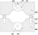
FIG. 2 is a cross-sectional view taken along line A-A of FIG. 1 in accordance with the present invention;
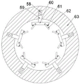
FIG. 3 is a cross-sectional view taken along line B-B of FIG. 1 in accordance with the present invention;
fig. 4 is a partial enlarged view of the invention at C in fig. 1.
Detailed Description
All of the features disclosed in this specification, or all of the steps in any method or process so disclosed, may be combined in any combination, except combinations and/or steps that are mutually exclusive.
The invention will now be described in detail with reference to fig. 1-4, for convenience of description, the following orientations will now be defined: the up, down, left, right, and front-back directions described below correspond to the up, down, left, right, and front-back directions in the projection relationship of fig. 1 itself.
The invention relates to automatic log scraping and polishing equipment, which comprises a machine body 10, wherein two supporting columns 68 are fixedly arranged on the lower side surface of the machine body 10, the supporting columns 68 support the machine body 10, a fourth fixing body 69 is fixedly arranged on the lower side surface of the machine body 10, a first fixing body 63, a second fixing body 64 and a third fixing body 66 are fixedly arranged on the upper side surface of the machine body 10, a transmission cavity 70 is arranged in the machine body 10 and the fourth fixing body 69, a power cavity 71 is arranged on the right side of the fourth fixing body 69, a reverse cavity 72 is arranged on the right side of the transmission cavity 70, a belt wheel cavity 73 is arranged on the right side of the reverse cavity 72, a conveying cavity 74 is arranged in the third fixing body 66, a conveying device 79 for conveying moving trees is arranged on the third fixing body 66, the conveying device 79 comprises a main motor 11 fixedly arranged on the lower side wall of the power cavity 71, the main motor 11 is in power connection with a motor shaft 12 which is rotatably connected between the power cavity 71 and the reverse cavity, a driving pulley 13 is fixedly arranged on the lower side of the motor shaft 12, a driving bevel gear 14 is fixedly arranged on the upper side of the motor shaft 12, a driven rotating shaft 23 is rotatably connected to the lower side wall of the transmission cavity 70, a driven pulley 24 is fixedly arranged on the lower side of the driven rotating shaft 23, a power belt 22 is connected between the driven pulley 24 and the driving pulley 13, a driven bevel gear 25 is fixedly arranged on the upper side of the driven rotating shaft 23, a connecting rotating shaft 26 is rotatably connected to the left and right side walls of the transmission cavity 70, a connecting bevel gear 27 meshed with the driven bevel gear 25 is fixedly arranged on the connecting rotating shaft 26, a connecting pulley 31 is fixedly arranged on the left side of the connecting rotating shaft 26, a reverse rotating shaft 20 is rotatably connected between the transmission cavity 70 and the reverse rotating cavity 72, a reverse rotating gear 21 is fixedly arranged on the left side of the reverse rotating shaft 20, a forward rotation rotating shaft 17 is rotatably connected between the reverse rotation cavity 72 and the belt wheel cavity 73, a forward rotation bevel gear 15 meshed with the driving bevel gear 14 is fixedly arranged on the left side of the forward rotation rotating shaft 17, a forward rotation belt wheel 18 is fixedly arranged on the right side of the forward rotation rotating shaft 17, a scraping device 77 for scraping wood is arranged in the second fixing body 64, and a polishing device 78 for grinding wood is arranged in the first fixing body 63.
Beneficially, two lifting connecting rods 41 are slidably connected in the third fixed body 66, the lifting connecting rods 41 are symmetrical front to back, a movable body 65 is fixedly arranged on each lifting connecting rod 41, a lifting spring 42 is connected between each movable body 65 and the third fixed body 66, a pressing cavity 75 is arranged in each movable body 65, two contact sliding rods 37 are slidably connected to the side wall of each pressing cavity 75, a contact spring 36 is fixedly arranged on each contact sliding rod 37, a rotating shaft sleeve 38 is fixedly arranged on the lower side of each contact sliding rod 37, a contact rotating shaft 39 rotatably connected to the side wall of each pressing cavity 75 is rotatably connected in each rotating shaft sleeve 38, two contact rollers 40 are fixedly arranged on each contact rotating shaft 39, a conveying rotating shaft 34 is rotatably connected to the side wall of each conveying cavity 74, a conveying belt wheel 33 is fixedly arranged on the right side of each conveying rotating shaft 34, and a connecting belt 32 is connected between each conveying belt wheel 33 and, the conveying rotating shaft 34 is fixedly provided with a conveying wheel 35, the conveying wheel 35 is provided with spiral stripes, so that a tree is placed between the movable body 65 and the third fixed body 66, the main motor 11 is started, the motor shaft 12 rotates to drive the driving pulley 13 and the driving bevel gear 14 to rotate, the driving pulley 13 drives the driven pulley 24 and the driven bevel gear 25 to rotate through the power belt 22, the driven bevel gear 25 drives the connecting bevel gear 27 and the connecting pulley 31 to rotate, the conveying pulley 33 and the conveying wheel 35 are driven to rotate through the connecting belt 32, the conveying wheel 35 moves and rotates to convey the tree into the device, the lifting spring 42 enables the movable body 65 to cling to the tree, the contact spring 36 enables the contact roller 40 to press the tree tightly, when the tree moves, the contact roller 40 rotates.
Advantageously, the scraping device 77 comprises a gear ring 43 rotatably mounted in the second fixed body 64, the gear ring 43 is engaged with the counter gear 21, four connecting blocks 44 distributed circumferentially are fixedly arranged on the left and right sides of the gear ring 43, a fixed pin 45 is fixedly arranged in each connecting block 44, a movable slider 46 is slidably connected on the fixed pin 45, a row of two movable sliders 46 is fixedly provided with a slant scraper 47, two positioning springs 67 are connected between each slant scraper 47 and the gear ring 43, four adjusting cavities 76 distributed circumferentially are respectively arranged on the left and right sides of the second fixed body 64, an adjusting rod 52 is rotatably connected in each adjusting cavity 76, an adjusting bevel gear 51 is fixedly arranged on each adjusting rod 52, a fixing nut 49 is fixedly arranged in the second fixed body 64, and a lead screw 48 in threaded connection with the fixing nut 49 is rotatably connected to the side wall of each adjusting cavity 76, a lead screw bevel gear 50 meshed with the adjusting bevel gear 51 is fixedly arranged on the lead screw 48, so that the four adjusting rods 52 on the right side are rotated, the adjusting bevel gear 51 rotates to drive the lead screw bevel gear 50 and the lead screw 48 to rotate, the lead screw 48 rotates and moves in the fixing nut 49, the lead screw 48 pushes the inclined scraper 47 to enable the inclined scraper 47 to incline towards the right side, the four inclined scrapers 47 form a cone shape, the distance between the inclined scrapers 47 is adjusted according to the size of a tree, when the tree enters the second fixing body 64, the driving bevel gear 14 rotates to drive the reverse bevel gear 16 and the reverse gear 21 to rotate, the reverse gear 21 drives the gear ring 43 to rotate, the inclined scrapers 47 rotate to scrape the surface of the tree, and the inclined scrapers 47 can cut the tree to a required diameter at one time.
Advantageously, the conveying device 79 comprises a positioning ring 57 rotatably mounted in the first fixed body 63, a pulley ring 53 is fixedly arranged on the positioning ring 57, six circumferentially distributed telescopic rods 55 are slidably connected in the pulley ring 53, a compression spring 54 is connected to each telescopic rod 55, a fastening wheel 56 is rotatably connected to the lower side of each telescopic rod 55, five circumferentially distributed grinding rods 59 are slidably connected in the pulley ring 53, a grinding spring 58 is connected to each grinding rod 59, a fixed grinding plate 60 is fixedly arranged on each grinding rod 59, a movable spring 62 is rotatably connected to each fixed grinding plate 60 on both sides, a movable grinding plate 61 is connected between each movable spring 62 and each fixed grinding plate 60, the fixed grinding plate 60 and the movable spring 62 grind the surface of the tree, so that when the tree continues to enter the first fixed body 63, the driving bevel gear 14 drives the forward bevel gear 15 and the forward belt wheel 18 to rotate, the forward belt wheel 18 drives the belt wheel ring 53 to rotate, the fastening wheel 56 rotates, the fastening wheel 56 tightly clamps the tree by the compression spring 54, the fastening wheel 56 drives the tree to rotate together, the rotation directions of the belt wheel ring 53 and the gear ring 43 are opposite, the fixed polishing plate 60 tightly presses the tree by the polishing spring 58, the movable polishing plate 61 tightly presses the movable spring 62 against the tree, and the fixed polishing plate 60 and the movable spring 62 rotate relative to the tree and grind the surface of the tree so as to smooth the surface of the tree.
In the initial state, the main motor 11 is not started, and the contact spring 36, the compression spring 54, and the sharpening spring 58 are relaxed.
When the tree planting machine starts to work, a tree is placed between the movable body 65 and the third fixed body 66, the main motor 11 is started, the motor shaft 12 rotates to drive the driving belt wheel 13 and the driving bevel gear 14 to rotate, the driving belt wheel 13 drives the driven belt wheel 24 and the driven bevel gear 25 to rotate through the power belt 22, the driven bevel gear 25 drives the connecting bevel gear 27 and the connecting belt wheel 31 to rotate, the conveying belt wheel 33 and the conveying wheel 35 are driven to rotate through the connecting belt 32, the tree is moved and rotated through the conveying wheel 35, the tree is conveyed into the machine, the movable body 65 is tightly attached to the tree through the lifting spring 42, the tree is tightly pressed through the contact roller 40 through the contact spring 36, when the tree moves, the contact roller 40 rotates to rotate, the four adjusting rods 52 on the right side are rotated, the adjusting bevel gear 51 rotates to drive the lead screw bevel gear 50 and the lead screw 48 to rotate and, the inclined scrapers 47 are inclined towards the right side, the four inclined scrapers 47 form a cone shape, the distance between the inclined scrapers 47 is adjusted according to the size of the tree, when the tree enters the second fixing body 64, the driving bevel gear 14 rotates to drive the reverse bevel gear 16 and the reverse gear 21 to rotate, the reverse gear 21 drives the gear ring 43 to rotate, the inclined scrapers 47 rotate to scrape the surface of the tree, the inclined scrapers 47 can cut the tree to a required diameter at one time, when the tree continues to move rightwards to enter the first fixing body 63, the driving bevel gear 14 drives the forward bevel gear 15 and the forward belt wheel 18 to rotate, the forward belt wheel 18 drives the belt wheel ring 53 to rotate, the fastening wheel 56 rotates, the compression spring 54 enables the fastening wheel 56 to cling to and clamp the tree, the fastening wheel 56 drives the tree to rotate together, the rotation directions of the belt wheel ring 53 and the gear ring 43 are opposite, the polishing spring 58 enables the fixed polishing plate 60 to cling, the stationary sanding plate 60 and the movable spring 62 rotate relative to the tree and abrade the surface of the tree to smooth the surface of the tree.
The above description is only an embodiment of the invention, but the scope of the invention is not limited thereto, and any changes or substitutions that are not thought of through the inventive work should be included in the scope of the invention. Therefore, the protection scope of the invention should be subject to the protection scope defined by the claims.
Claims (4)
1. The utility model provides an automatic equipment of polishing of strickleing off of log, includes the organism, its characterized in that: the tree planting machine is characterized in that two support columns are fixedly arranged on the lower side surface of the machine body, the machine body is supported by the support columns, a fourth fixing body is fixedly arranged on the lower side surface of the machine body, a first fixing body, a second fixing body and a third fixing body are fixedly arranged on the upper side surface of the machine body, transmission cavities are formed in the machine body and the fourth fixing body, a power cavity is formed in the right side of the fourth fixing body, a reverse rotation cavity is formed in the right side of the transmission cavity, a belt wheel cavity is formed in the right side of the reverse rotation cavity, a conveying cavity is formed in the third fixing body, and a conveying device for conveying and moving trees is; the conveying device comprises a main motor fixedly arranged on the lower side wall of the power cavity, the main motor is in power connection with a motor shaft which is rotatably connected between the power cavity and the reverse rotation cavity, a driving belt wheel is fixedly arranged on the lower side of the motor shaft, a driving bevel gear is fixedly arranged on the upper side of the motor shaft, a driven rotating shaft is rotatably connected on the lower side wall of the transmission cavity, a driven belt wheel is fixedly arranged on the lower side of the driven rotating shaft, a power belt is connected between the driven belt wheel and the driving belt wheel, a driven bevel gear is fixedly arranged on the upper side of the driven rotating shaft, connecting rotating shafts are rotatably connected on the left side wall and the right side wall of the transmission cavity, connecting bevel gears meshed with the driven bevel gears are fixedly arranged on the connecting rotating shafts, a connecting belt wheel is fixedly arranged on the left side of the connecting, a reverse bevel gear meshed with the driving bevel gear is fixedly arranged on the right side of the reverse rotating shaft, a forward rotating shaft is rotatably connected between the reverse rotating cavity and the belt wheel cavity, a forward bevel gear meshed with the driving bevel gear is fixedly arranged on the left side of the forward rotating shaft, and a forward belt wheel is fixedly arranged on the right side of the forward rotating shaft; the second fixing body is internally provided with a scraping device for scraping wood, and the first fixing body is internally provided with a grinding device for grinding wood.
2. The automatic log scraping and polishing device according to claim 1, characterized in that: the lifting connecting rod of symmetry around sliding connection has two in the third fixed body, the activity has set firmly on the lifting connecting rod, the activity with be connected with the lift spring between the third fixed body, be equipped with in the activity and compress tightly the chamber, it has two contact slide bars to compress tightly side wall sliding connection in the chamber, every contact spring has set firmly on the contact slide bar, the contact slide bar downside has set firmly the pivot cover, rotate in the pivot cover and be connected with compress tightly the contact pivot of chamber side wall rotation connection, two contact rollers have set firmly in the contact pivot, it is connected with the transport pivot to carry the chamber lateral wall rotation, carry the pivot right side to set firmly band pulley, band pulley with be connected with the connection belt between the band pulley, the delivery wheel has set firmly in the transport pivot, be equipped with the spiral stripe on the delivery wheel.
3. The automatic log scraping and polishing device according to claim 1, characterized in that: the scraping device comprises a gear ring which is rotatably arranged in the second fixed body and is meshed with the counter gear, the left side and the right side of the gear ring are respectively and fixedly provided with four connecting blocks which are distributed circumferentially, a fixed pin shaft is fixedly arranged in each connecting block, the fixed pin shaft is connected with movable sliding blocks in a sliding way, inclined scrapers are fixedly arranged on two movable sliding blocks in a row, two positioning springs are connected between each inclined scraper and the gear ring, the left side and the right side of the second fixed body are respectively provided with four adjusting cavities which are distributed circumferentially, adjusting rods are rotatably connected in the adjusting cavities, an adjusting bevel gear is fixedly arranged on the adjusting rod, a fixing nut is fixedly arranged in the second fixing body, the side wall of the adjusting cavity is rotatably connected with a screw rod in threaded connection with the fixing nut, and a screw rod bevel gear meshed with the adjusting bevel gear is fixedly arranged on the screw rod.
4. The automatic log scraping and polishing device according to claim 1, characterized in that: conveyor installs including rotating the holding ring in the first fixed body, the band pulley ring has set firmly on the holding ring, sliding connection has six circumference distribution's telescopic link in the band pulley ring, every be connected with compression spring on the telescopic link, the telescopic link downside rotates and is connected with the tight pulley, sliding connection has five circumference distribution's the pole of polishing in the band pulley ring, every be connected with the spring of polishing on the pole of polishing, the fixed board of polishing has set firmly on the pole of polishing, every fixed board both sides of polishing rotate and are connected with the activity spring, the activity spring with be connected with the activity board of polishing between the fixed board of polishing, fixed board of polishing with the activity spring trees surface of polishing.
Priority Applications (1)
| Application Number | Priority Date | Filing Date | Title |
|---|---|---|---|
| CN202010706000.9A CN111791331A (en) | 2020-07-21 | 2020-07-21 | Automatic equipment of polishing of strickleing off of log |
Applications Claiming Priority (1)
| Application Number | Priority Date | Filing Date | Title |
|---|---|---|---|
| CN202010706000.9A CN111791331A (en) | 2020-07-21 | 2020-07-21 | Automatic equipment of polishing of strickleing off of log |
Publications (1)
| Publication Number | Publication Date |
|---|---|
| CN111791331A true CN111791331A (en) | 2020-10-20 |
Family
ID=72807933
Family Applications (1)
| Application Number | Title | Priority Date | Filing Date |
|---|---|---|---|
| CN202010706000.9A Withdrawn CN111791331A (en) | 2020-07-21 | 2020-07-21 | Automatic equipment of polishing of strickleing off of log |
Country Status (1)
| Country | Link |
|---|---|
| CN (1) | CN111791331A (en) |
Cited By (3)
| Publication number | Priority date | Publication date | Assignee | Title |
|---|---|---|---|---|
| CN112757402A (en) * | 2020-12-08 | 2021-05-07 | 陈朝朝 | Processing equipment of golf tee |
| CN112757406A (en) * | 2021-01-15 | 2021-05-07 | 付野 | Log cuts open light device |
| CN113290645A (en) * | 2021-06-18 | 2021-08-24 | 石强 | Energy-saving building material processingequipment |
-
2020
- 2020-07-21 CN CN202010706000.9A patent/CN111791331A/en not_active Withdrawn
Cited By (4)
| Publication number | Priority date | Publication date | Assignee | Title |
|---|---|---|---|---|
| CN112757402A (en) * | 2020-12-08 | 2021-05-07 | 陈朝朝 | Processing equipment of golf tee |
| CN112757406A (en) * | 2021-01-15 | 2021-05-07 | 付野 | Log cuts open light device |
| CN113290645A (en) * | 2021-06-18 | 2021-08-24 | 石强 | Energy-saving building material processingequipment |
| CN113290645B (en) * | 2021-06-18 | 2022-06-21 | 石强 | Energy-saving building material processingequipment |
Similar Documents
| Publication | Publication Date | Title |
|---|---|---|
| CN111791331A (en) | Automatic equipment of polishing of strickleing off of log | |
| CN214771016U (en) | Deckle edge clearing device for plate processing | |
| CN112605810A (en) | Circular goods polishing equipment of polishing of carpenter | |
| CN209240212U (en) | A kind of ecology is exempted to paint solid wood board automatic processing apparatus | |
| CN101804598A (en) | Chopstick polisher | |
| CN111546182B (en) | Intelligent manufacturing equilateral triangle workpiece polishing device | |
| CN209477934U (en) | A kind of novel roll shaft polishing machine | |
| CN211306601U (en) | Cutting and grinding device for bed board of solid wood bed | |
| CN207480290U (en) | One kind processes edging device for plank | |
| CN216371630U (en) | Plastic outer surface layer polishing device for plastic product processing | |
| CN115008282A (en) | Hollow floor production and processing device | |
| CN107378685A (en) | A kind of radial brick corner sanding apparatus | |
| CN212264759U (en) | Numerical control gear hobbing machine | |
| CN210756778U (en) | Efficient spiller grinding apparatus | |
| CN113001267A (en) | Motor rotor shaft forming and processing technology | |
| CN209175496U (en) | A kind of surface polishing device of handware processing | |
| CN112338695B (en) | Log piece burring equipment | |
| CN112454148A (en) | Multi-dimensional precise tungsten drill rotary extrusion type nondestructive bracelet polishing machine | |
| CN218312789U (en) | Burnishing device is used in grinding ball production and processing | |
| CN218518821U (en) | Automatic discharging plate cutting machine for furniture processing | |
| CN214025134U (en) | Intelligent burnishing device is used in production of wooden chopsticks | |
| CN213498505U (en) | Woodworking sander with material guiding device | |
| CN219599035U (en) | Bamboo let polishing equipment | |
| CN113070966B (en) | Intelligent household dining chair processing equipment and method | |
| CN210160852U (en) | Grinding device is used in gear shaft production and processing |
Legal Events
| Date | Code | Title | Description |
|---|---|---|---|
| PB01 | Publication | ||
| PB01 | Publication | ||
| SE01 | Entry into force of request for substantive examination | ||
| SE01 | Entry into force of request for substantive examination | ||
| WW01 | Invention patent application withdrawn after publication | ||
| WW01 | Invention patent application withdrawn after publication |
Application publication date: 20201020 |