CN111780314A - Ventilation energy-saving system of green building - Google Patents
Ventilation energy-saving system of green building Download PDFInfo
- Publication number
- CN111780314A CN111780314A CN202010628459.1A CN202010628459A CN111780314A CN 111780314 A CN111780314 A CN 111780314A CN 202010628459 A CN202010628459 A CN 202010628459A CN 111780314 A CN111780314 A CN 111780314A
- Authority
- CN
- China
- Prior art keywords
- ventilation
- roof
- fan
- saving system
- wall
- Prior art date
- Legal status (The legal status is an assumption and is not a legal conclusion. Google has not performed a legal analysis and makes no representation as to the accuracy of the status listed.)
- Pending
Links
- 238000009423 ventilation Methods 0.000 title claims abstract description 61
- OKTJSMMVPCPJKN-UHFFFAOYSA-N Carbon Chemical compound [C] OKTJSMMVPCPJKN-UHFFFAOYSA-N 0.000 claims abstract description 21
- 229910052799 carbon Inorganic materials 0.000 claims abstract description 3
- 238000004134 energy conservation Methods 0.000 claims abstract description 3
- 238000011282 treatment Methods 0.000 claims description 3
- 239000002699 waste material Substances 0.000 claims description 3
- 230000000712 assembly Effects 0.000 claims description 2
- 238000000429 assembly Methods 0.000 claims description 2
- 230000008878 coupling Effects 0.000 claims 3
- 238000010168 coupling process Methods 0.000 claims 3
- 238000005859 coupling reaction Methods 0.000 claims 3
- 238000000034 method Methods 0.000 claims 1
- 238000004321 preservation Methods 0.000 claims 1
- WABPQHHGFIMREM-YPZZEJLDSA-N lead-205 Chemical compound [205Pb] WABPQHHGFIMREM-YPZZEJLDSA-N 0.000 description 4
- 230000007613 environmental effect Effects 0.000 description 3
- 238000012545 processing Methods 0.000 description 3
- 238000009413 insulation Methods 0.000 description 2
- 230000004075 alteration Effects 0.000 description 1
- 230000009286 beneficial effect Effects 0.000 description 1
- 238000004891 communication Methods 0.000 description 1
- 239000004020 conductor Substances 0.000 description 1
- 238000010586 diagram Methods 0.000 description 1
- 239000000428 dust Substances 0.000 description 1
- 238000005516 engineering process Methods 0.000 description 1
- 230000003993 interaction Effects 0.000 description 1
- 239000011490 mineral wool Substances 0.000 description 1
- 238000012986 modification Methods 0.000 description 1
- 230000004048 modification Effects 0.000 description 1
- 239000003973 paint Substances 0.000 description 1
- 238000010248 power generation Methods 0.000 description 1
- 238000005507 spraying Methods 0.000 description 1
- 238000006467 substitution reaction Methods 0.000 description 1
- 229920002994 synthetic fiber Polymers 0.000 description 1
Images


Classifications
-
- F—MECHANICAL ENGINEERING; LIGHTING; HEATING; WEAPONS; BLASTING
- F24—HEATING; RANGES; VENTILATING
- F24F—AIR-CONDITIONING; AIR-HUMIDIFICATION; VENTILATION; USE OF AIR CURRENTS FOR SCREENING
- F24F7/00—Ventilation
- F24F7/007—Ventilation with forced flow
-
- F—MECHANICAL ENGINEERING; LIGHTING; HEATING; WEAPONS; BLASTING
- F03—MACHINES OR ENGINES FOR LIQUIDS; WIND, SPRING, OR WEIGHT MOTORS; PRODUCING MECHANICAL POWER OR A REACTIVE PROPULSIVE THRUST, NOT OTHERWISE PROVIDED FOR
- F03D—WIND MOTORS
- F03D9/00—Adaptations of wind motors for special use; Combinations of wind motors with apparatus driven thereby; Wind motors specially adapted for installation in particular locations
- F03D9/10—Combinations of wind motors with apparatus storing energy
- F03D9/11—Combinations of wind motors with apparatus storing energy storing electrical energy
-
- F—MECHANICAL ENGINEERING; LIGHTING; HEATING; WEAPONS; BLASTING
- F04—POSITIVE - DISPLACEMENT MACHINES FOR LIQUIDS; PUMPS FOR LIQUIDS OR ELASTIC FLUIDS
- F04D—NON-POSITIVE-DISPLACEMENT PUMPS
- F04D25/00—Pumping installations or systems
- F04D25/02—Units comprising pumps and their driving means
- F04D25/04—Units comprising pumps and their driving means the pump being fluid-driven
-
- F—MECHANICAL ENGINEERING; LIGHTING; HEATING; WEAPONS; BLASTING
- F24—HEATING; RANGES; VENTILATING
- F24F—AIR-CONDITIONING; AIR-HUMIDIFICATION; VENTILATION; USE OF AIR CURRENTS FOR SCREENING
- F24F13/00—Details common to, or for air-conditioning, air-humidification, ventilation or use of air currents for screening
- F24F13/28—Arrangement or mounting of filters
-
- H—ELECTRICITY
- H02—GENERATION; CONVERSION OR DISTRIBUTION OF ELECTRIC POWER
- H02S—GENERATION OF ELECTRIC POWER BY CONVERSION OF INFRARED RADIATION, VISIBLE LIGHT OR ULTRAVIOLET LIGHT, e.g. USING PHOTOVOLTAIC [PV] MODULES
- H02S40/00—Components or accessories in combination with PV modules, not provided for in groups H02S10/00 - H02S30/00
- H02S40/30—Electrical components
- H02S40/38—Energy storage means, e.g. batteries, structurally associated with PV modules
-
- Y—GENERAL TAGGING OF NEW TECHNOLOGICAL DEVELOPMENTS; GENERAL TAGGING OF CROSS-SECTIONAL TECHNOLOGIES SPANNING OVER SEVERAL SECTIONS OF THE IPC; TECHNICAL SUBJECTS COVERED BY FORMER USPC CROSS-REFERENCE ART COLLECTIONS [XRACs] AND DIGESTS
- Y02—TECHNOLOGIES OR APPLICATIONS FOR MITIGATION OR ADAPTATION AGAINST CLIMATE CHANGE
- Y02B—CLIMATE CHANGE MITIGATION TECHNOLOGIES RELATED TO BUILDINGS, e.g. HOUSING, HOUSE APPLIANCES OR RELATED END-USER APPLICATIONS
- Y02B10/00—Integration of renewable energy sources in buildings
- Y02B10/10—Photovoltaic [PV]
-
- Y—GENERAL TAGGING OF NEW TECHNOLOGICAL DEVELOPMENTS; GENERAL TAGGING OF CROSS-SECTIONAL TECHNOLOGIES SPANNING OVER SEVERAL SECTIONS OF THE IPC; TECHNICAL SUBJECTS COVERED BY FORMER USPC CROSS-REFERENCE ART COLLECTIONS [XRACs] AND DIGESTS
- Y02—TECHNOLOGIES OR APPLICATIONS FOR MITIGATION OR ADAPTATION AGAINST CLIMATE CHANGE
- Y02B—CLIMATE CHANGE MITIGATION TECHNOLOGIES RELATED TO BUILDINGS, e.g. HOUSING, HOUSE APPLIANCES OR RELATED END-USER APPLICATIONS
- Y02B10/00—Integration of renewable energy sources in buildings
- Y02B10/30—Wind power
-
- Y—GENERAL TAGGING OF NEW TECHNOLOGICAL DEVELOPMENTS; GENERAL TAGGING OF CROSS-SECTIONAL TECHNOLOGIES SPANNING OVER SEVERAL SECTIONS OF THE IPC; TECHNICAL SUBJECTS COVERED BY FORMER USPC CROSS-REFERENCE ART COLLECTIONS [XRACs] AND DIGESTS
- Y02—TECHNOLOGIES OR APPLICATIONS FOR MITIGATION OR ADAPTATION AGAINST CLIMATE CHANGE
- Y02E—REDUCTION OF GREENHOUSE GAS [GHG] EMISSIONS, RELATED TO ENERGY GENERATION, TRANSMISSION OR DISTRIBUTION
- Y02E10/00—Energy generation through renewable energy sources
- Y02E10/50—Photovoltaic [PV] energy
-
- Y—GENERAL TAGGING OF NEW TECHNOLOGICAL DEVELOPMENTS; GENERAL TAGGING OF CROSS-SECTIONAL TECHNOLOGIES SPANNING OVER SEVERAL SECTIONS OF THE IPC; TECHNICAL SUBJECTS COVERED BY FORMER USPC CROSS-REFERENCE ART COLLECTIONS [XRACs] AND DIGESTS
- Y02—TECHNOLOGIES OR APPLICATIONS FOR MITIGATION OR ADAPTATION AGAINST CLIMATE CHANGE
- Y02E—REDUCTION OF GREENHOUSE GAS [GHG] EMISSIONS, RELATED TO ENERGY GENERATION, TRANSMISSION OR DISTRIBUTION
- Y02E10/00—Energy generation through renewable energy sources
- Y02E10/70—Wind energy
- Y02E10/72—Wind turbines with rotation axis in wind direction
-
- Y—GENERAL TAGGING OF NEW TECHNOLOGICAL DEVELOPMENTS; GENERAL TAGGING OF CROSS-SECTIONAL TECHNOLOGIES SPANNING OVER SEVERAL SECTIONS OF THE IPC; TECHNICAL SUBJECTS COVERED BY FORMER USPC CROSS-REFERENCE ART COLLECTIONS [XRACs] AND DIGESTS
- Y02—TECHNOLOGIES OR APPLICATIONS FOR MITIGATION OR ADAPTATION AGAINST CLIMATE CHANGE
- Y02E—REDUCTION OF GREENHOUSE GAS [GHG] EMISSIONS, RELATED TO ENERGY GENERATION, TRANSMISSION OR DISTRIBUTION
- Y02E70/00—Other energy conversion or management systems reducing GHG emissions
- Y02E70/30—Systems combining energy storage with energy generation of non-fossil origin
Landscapes
- Engineering & Computer Science (AREA)
- Mechanical Engineering (AREA)
- General Engineering & Computer Science (AREA)
- Chemical & Material Sciences (AREA)
- Combustion & Propulsion (AREA)
- Power Engineering (AREA)
- Life Sciences & Earth Sciences (AREA)
- Sustainable Development (AREA)
- Sustainable Energy (AREA)
- Building Environments (AREA)
Abstract
The invention discloses a ventilation energy-saving system of a green building, which comprises a wall body, a roof, a top plate and a storage battery, wherein the roof is installed at the upper end of the wall body, the top plate is fixedly connected above the inner wall of the wall body, the storage battery is installed at the center of the upper end of the top plate, and the inner side and the outer side of the inner wall of a shell are respectively fixedly connected with active carbon and a filter screen. This ventilation economizer system of green building, structure scientific and reasonable, convenience safe in utilization, be provided with first wire, the second wire, the third wire, the battery, the fan, the switch, unpowered fan, cooperation between vertical axis aerogenerator and the solar panel, the fan ventilation under the windless condition and the unpowered fan ventilation under the windy condition realize the ventilation energy-conservation to green building, and can save the output power of battery under windy state, the problem of prior art can't carry out different ventilation under windy or windless condition and handle has been avoided.
Description
Technical Field
The invention relates to the technical field of green buildings, in particular to a ventilation energy-saving system of a green building.
Background
The green building has the advantages of reasonable layout, minimizing the use of synthetic materials as much as possible, fully utilizing sunlight, saving energy, creating a feeling close to nature for residents, and aiming at the coordinated development of people, buildings and natural environment, however, although the green building in the prior art can realize the energy saving of building ventilation, the prior art still has the problem that different ventilation processing can not be carried out under the condition of wind or no wind.
Disclosure of Invention
The invention aims to provide a ventilation energy-saving system of a green building, which solves the problem that different ventilation treatments cannot be carried out under windy or no wind conditions in the background technology.
In order to achieve the purpose, the invention provides the following technical scheme: a ventilation energy-saving system of a green building comprises a wall body, a roof, a top plate and storage batteries, wherein the roof is installed at the upper end of the wall body, the top plate is fixedly connected above the inner wall of the wall body, the storage batteries are installed in the centers of the upper ends of the top plate, and electric ventilation assemblies are installed above the left side and the right side of the wall body;
the electric ventilation assembly comprises a switch, a shell, a fan, activated carbon, a first lead and a filter screen;
all link to each other through first wire electrical property between switch, fan and the battery, the outside of fan passes through the casing and links to each other with the wall body is fixed, the inside and outside both sides of inner wall of casing link to each other with active carbon and filter screen are fixed respectively.
Preferably, the left and right casings, the activated carbon and the filter screen are axially symmetrically distributed by taking the vertical center of the top plate as a reference.
Preferably, an environmental protection assembly is arranged above the roof;
the environment-friendly component comprises a second conducting wire, a vertical axis wind driven generator, a screw, a supporting seat, an upright post, a third conducting wire and a solar panel;
the left and right supporting seats are fixedly connected to the left and right sides of the upper end of a roof respectively, a plurality of solar panels are installed inside the upper portion of the supporting seats, the solar panels are electrically connected with a storage battery through a supporting group and a second conducting wire, a plurality of upright columns are fixedly connected with the upper end of the roof, a vertical axis wind driven generator is installed above the upright columns through screws, and the lower portion of the vertical axis wind driven generator is electrically connected with the storage battery through a third conducting wire.
Preferably, the lower end inclined plane of the supporting seat and the upper end inclined plane of the roof have the same angle.
Preferably, the vertical center of the vertical axis wind turbine coincides with the vertical center of the roof.
Preferably, an automatic ventilation assembly is installed at the roof;
the automatic ventilation assembly comprises a vertical pipe and an unpowered fan;
the upper side and the lower side of the outer wall of the vertical pipe are fixedly connected with the roof and the top plate respectively, and the upper end of the outer wall of the vertical pipe is connected with the unpowered fan in a rotating mode.
Preferably, the lower end of the roof is fixedly connected with the top plate through a support, a waterproof layer is processed inside the upper end of the roof, and a heat insulation layer is processed on the outer wall of the wall body.
Preferably, the left side and the right side of the upper end of the roof are inclined at an angle of 10-15 degrees.
The application of the ventilation energy-saving system of the green building specifically comprises the following steps:
s1, firstly, a user can install the first lead, the second lead and the third lead in electrical connection with the storage battery, and then under the use condition of the green building, if breeze not less than a meter exists, the unpowered fan can start to rotate, and the air flow between the interior of the building and the outside is ensured.
S2, when wind power and sunlight are sufficient, the vertical axis wind driven generator and the solar panel can charge the storage battery through the second lead and the third lead respectively, so that the power in the storage battery is sufficient, and the vertical axis wind driven generator and the solar panel can be used under the condition of no wind.
S3, the user can press the switch to connect the circuit of the first lead, the fan is started to realize the gas flow inside the building and outside, the ventilation energy saving of the green building is realized through the fan ventilation under the windless condition and the unpowered fan ventilation under the windy condition, the output power of the storage battery can be saved under the windy condition, the storage battery can be used as other power of the green building, the problem that the prior art cannot perform different ventilation treatment under the windy or windless condition is avoided, and the resource waste of a certain degree can still be caused.
Compared with the prior art, the invention has the beneficial effects that:
this ventilation economizer system of green building through being provided with first wire, second wire, third wire, battery, fan, switch, unpowered fan, the cooperation between vertical axis aerogenerator and the solar panel, has the breeze that is not less than 0.2 meters, and the unpowered fan can begin to start, energy-concerving and environment-protective.
According to the ventilation energy-saving system of the green building, when wind power and sunlight are sufficient, the vertical axis wind driven generator and the solar panel can ensure that the power in the storage battery is abundant.
This ventilation economizer system of green building makes when using under the windless condition, and the user can press the switch, and the fan starts, ventilates through the fan under the windless condition and ventilates the unpowered fan under the windy condition and realize the ventilation energy-conservation to green building.
This ventilation economizer system of green building can save the output power of battery under windy state, has avoided prior art can't carry out the problem of different ventilation processings under windy or windless condition.
Drawings
FIG. 1 is a schematic structural view of the present invention;
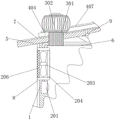
FIG. 2 is a schematic view of the roof, support and unpowered fan of FIG. 1;
FIG. 3 is a schematic view of the structure of FIG. 1 at the roof, fan and first conductor;
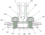
FIG. 4 is a schematic view of the structure of the column, the supporting base and the third wire of FIG. 2;
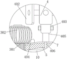
FIG. 5 is a schematic view of the structure of FIG. 3 at the roof, the support pedestals and the risers;
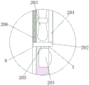
fig. 6 is a schematic structural diagram of the wall, the casing and the activated carbon in fig. 3.
In the figure: 1. the wind power generation device comprises a wall body, 2, an electric ventilation assembly, 201, a switch, 202, a machine shell, 203, a fan, 204, activated carbon, 205, a first wire, 206, a filter screen, 3, an automatic ventilation assembly, 301, a vertical pipe, 302, an unpowered fan, 4, an environment-friendly assembly, 401, a second wire, 402, a vertical axis wind driven generator, 403, a screw, 404, a supporting seat, 405, a stand column, 406, a third wire, 407, a solar panel, 5, a roof, 6, a top plate, 7, a waterproof layer, 8, a heat insulation layer, 9, a support, 10 and a storage battery.
Detailed Description
The technical solutions in the embodiments of the present invention will be clearly and completely described below with reference to the drawings in the embodiments of the present invention, and it is obvious that the described embodiments are only a part of the embodiments of the present invention, and not all of the embodiments. All other embodiments, which can be derived by a person skilled in the art from the embodiments given herein without making any creative effort, shall fall within the protection scope of the present invention.
Referring to fig. 1-6, the present invention provides a technical solution:
example 1
A ventilation energy-saving system of a green building comprises a wall body 1, a roof 5, a top plate 6 and a storage battery 10, wherein the roof 5 is installed at the upper end of the wall body 1, the top plate 6 is fixedly connected above the inner wall of the wall body 1, the storage battery 10 is installed at the center of the upper end of the top plate 6, the top plate 6 can support the storage battery 10, an electric ventilation assembly 2 is installed inside the upper portion of the left side and the right side of the wall body 1, the electric ventilation assembly 2 comprises a switch 201, a casing 202, a fan 203, activated carbon 204, a first lead 205 and a filter screen 206, the switch 201, the fan 203 and the storage battery 10 are electrically connected through the first lead 205, a connecting circuit among the first leads 205 can be controlled through the switch 201, the outer side of the fan 203 is fixedly connected with the wall body 1 through the casing 202, the wall body 1 can support the fan 203 through the casing 202, the activated carbon 204 can prevent the indoor and outdoor peculiar smell from flowing, the filter screen 206 can prevent the outdoor dust from entering the room, and the left and right machine shells 202, the activated carbon 204 and the filter screen 206 are axially symmetrically distributed by taking the vertical center of the top plate 6 as a reference.
Example 2
As an optional case, referring to fig. 1, 4 and 5, in the ventilation and energy saving system of green buildings, an environmental protection component 4 is installed above a roof 5, the environmental protection component 4 includes a second wire 401, a vertical axis wind turbine 402, a screw 403, a support base 404, a vertical column 405, a third wire 406 and a solar panel 407, the left and right support bases 404 are respectively fixedly connected to the left and right sides of the upper end of the roof 5, the roof 5 can support the support bases 404, a plurality of solar panels 407 are installed inside the support bases 404, the plurality of solar panels 407 are electrically connected to a storage battery 10 through the support sets 404 and the second wire 401, current generated at the solar panels 407 can charge the storage battery 10 through the support sets 404 and the second wire 401, the upper end of the roof 5 is fixedly connected to a plurality of vertical columns 405, the vertical axis wind turbine 402 is installed above the vertical column 405 through the screw 403, the lower end of the vertical axis wind turbine 402 is electrically connected to the storage battery, the current generated at the vertical axis wind turbine 402 can charge the battery 10 through the third wire 406, the lower end slope of the support base 404 is at the same angle as the upper end slope of the roof 5, and the vertical center of the vertical axis wind turbine 402 is at the same position as the vertical center of the roof 5, thereby limiting the relative positions of the roof 5 and the vertical axis wind turbine 402.
The scheme in this embodiment can be selectively combined with the scheme in other embodiments.
Example 3
As an optional situation, referring to fig. 2, 3, 4 and 5, in the ventilation energy-saving system of a green building, an automatic ventilation assembly 3 is installed at a roof 5, the automatic ventilation assembly 3 includes a vertical pipe 301 and an unpowered fan 302, the upper side and the lower side of the outer wall of the vertical pipe 301 are respectively fixedly connected with the roof 5 and a roof 6, the vertical pipe 301 can provide a passage for gas flow, the upper end of the outer wall of the vertical pipe 301 is rotatably connected with the unpowered fan 302, the unpowered fan 302 can realize wind flow under the condition of wind flow, the lower end of the roof 5 is fixedly connected with the roof 6 through a bracket 9, a waterproof layer 7 is processed inside the upper end of the roof 5, the waterproof layer 7 is formed by spraying waterproof paint, an insulating layer 8 is processed on the outer wall of a wall 1, the insulating layer 8 can be insulated by rock wool, and the left.
The scheme in this embodiment can be selectively combined with the scheme in other embodiments.
Example 4
When the ventilation energy-saving system is used, firstly, a user can install a first lead 205, a second lead 401 and a third lead 406 which are electrically connected with a storage battery 10, then, under the condition of using the green building, if breeze not less than 0.2 meter exists, an unpowered fan 302 can start to rotate to ensure that gas in the building and the outside can flow, meanwhile, when wind power and sunlight are sufficient, a vertical axis wind driven generator 402 and a solar panel 407 can respectively charge the storage battery 10 through the second lead 401 and the third lead 406 to ensure that the power in the storage battery 10 is sufficient, when the ventilation energy-saving system is used under the condition of no wind, the user can press a switch 201 to enable a circuit at the first lead 205 to be communicated, the fan 203 is started to realize the gas flow between the building and the outside, and the ventilation energy-saving of the green building is realized through the ventilation of the fan 203 under the condition of no wind and the ventilation of the unpowered fan 302 under the condition of wind, the output power of the storage battery 10 can be saved in a windy state, and the storage battery can be used as other power of green buildings, so that the problem that different ventilation processing cannot be carried out in the windy or windless state in the prior art is solved, and resource waste is still caused to a certain degree.
The scheme in this embodiment can be selectively combined with the scheme in other embodiments.
In the description of the present invention, it is to be understood that the terms "coaxial", "bottom", "one end", "top", "middle", "other end", "upper", "one side", "top", "inner", "front", "center", "both ends", and the like, indicate orientations or positional relationships based on those shown in the drawings, and are only for convenience of description and simplicity of description, and do not indicate or imply that the referenced device or element must have a particular orientation, be constructed and operated in a particular orientation, and thus, are not to be construed as limiting the present invention.
In the present invention, unless otherwise expressly specified or limited, the terms "mounted," "disposed," "connected," "secured," "screwed" and the like are to be construed broadly, e.g., as meaning fixedly connected, detachably connected, or integrally formed; can be mechanically or electrically connected; the terms may be directly connected or indirectly connected through an intermediate, and may be communication between two elements or interaction relationship between two elements, unless otherwise specifically limited, and the specific meaning of the terms in the present invention will be understood by those skilled in the art according to specific situations.
Although embodiments of the present invention have been shown and described, it will be appreciated by those skilled in the art that changes, modifications, substitutions and alterations can be made in these embodiments without departing from the principles and spirit of the invention, the scope of which is defined in the appended claims and their equivalents.
Claims (9)
1. The utility model provides a ventilation economizer system of green building, includes wall body (1), roof (5), roof (6) and battery (10), roof (5) are installed to the upper end of wall body (1), the inner wall top rigid coupling of wall body (1) has roof (6), battery (10), its characterized in that are installed at the upper end center of roof (6): electric ventilation assemblies (2) are arranged inside the upper parts of the left side and the right side of the wall body (1);
the electric ventilation assembly (2) comprises a switch (201), a casing (202), a fan (203), activated carbon (204), a first lead (205) and a filter screen (206);
switch (201), fan (203) and battery (10) between all link to each other through first wire (205) electrical property, the outside of fan (203) is passed through casing (202) and is fixed continuous with wall body (1), the inside and outside both sides of inner wall of casing (202) are fixed continuous with active carbon (204) and filter screen (206) respectively.
2. The ventilation energy-saving system for green buildings according to claim 1, characterized in that: the left and right machine shell (202), the activated carbon (204) and the filter screen (206) are all distributed in axial symmetry by taking the vertical center of the top plate (6) as a reference.
3. The ventilation energy-saving system for green buildings according to claim 1, characterized in that: an environment-friendly component (4) is arranged above the roof (5);
the environment-friendly assembly (4) comprises a second conducting wire (401), a vertical axis wind driven generator (402), a screw (403), a supporting seat (404), a vertical column (405), a third conducting wire (406) and a solar panel (407);
control supporting seat (404) rigid coupling is in the upper end left and right sides of roof (5) respectively, the top internally mounted of supporting seat (404) has a plurality of solar panel (407), and is a plurality of solar panel (407) all link to each other with battery (10) electrical property through supporting group (404) and second wire (401), and is a plurality of the equal rigid coupling of stand (405) has the upper end of roof (5), vertical axis aerogenerator (402) is installed through screw (403) in the top of stand (405), the below of vertical axis aerogenerator (402) links to each other with battery (10) electrical property through third wire (406).
4. The ventilation energy-saving system for green buildings according to claim 3, characterized in that: the lower end inclined plane of the supporting seat (404) has the same angle with the upper end inclined plane of the roof (5).
5. The ventilation energy-saving system for green buildings according to claim 3, characterized in that: the vertical center of the vertical axis wind turbine (402) is consistent with the vertical center of the roof (5).
6. The ventilation energy-saving system for green buildings according to claim 1, characterized in that: an automatic ventilation assembly (3) is arranged on the roof (5);
the automatic ventilation assembly (3) comprises a vertical pipe (301) and an unpowered fan (302);
the upper side and the lower side of the outer wall of the vertical pipe (301) are fixedly connected with a roof (5) and a top plate (6) respectively, and the upper end of the outer wall of the vertical pipe (301) is rotatably connected with an unpowered fan (302).
7. The ventilation energy-saving system for green buildings according to claim 1, characterized in that: the lower end of the roof (5) is fixedly connected with the top plate (6) through a support (9), a waterproof layer (7) is processed inside the upper end of the roof (5), and a heat preservation layer (8) is processed on the outer wall of the wall body (1).
8. The ventilation energy-saving system for green buildings according to claim 1, characterized in that: the left side and the right side of the upper end of the roof (5) are inclined at an angle of 10-15 degrees.
9. Use of a ventilation and energy saving system for green buildings according to claims 1 to 8, characterized in that: the method specifically comprises the following steps:
s1, firstly, a user can install the first lead (205), the second lead (401) and the third lead (406) and the storage battery (10) in an electrical connection mode, and then under the use condition of the green building, if breeze not less than 0.2 meter exists, the unpowered fan (302) can start to rotate, and air flow between the interior of the building and the outside is guaranteed.
S2, when wind power and sunlight are sufficient, the vertical axis wind driven generator (402) and the solar panel (407) can respectively charge the storage battery (10) through the second lead (401) and the third lead (406), so that the power in the storage battery (10) is sufficient, and the wind driven generator can be used under the condition of no wind.
S3, a user can press the switch (201), the circuit at the first lead (205) is communicated, the fan (203) is started, the gas flow inside the building and the outside is realized, the ventilation energy conservation of the green building is realized through the ventilation of the fan (203) under the windless condition and the ventilation of the unpowered fan (302) under the windless condition, the output power of the storage battery (10) can be saved under the windy condition, the green building can be used for other electric power, the problem that the prior art cannot perform different ventilation treatment under the windy or windless condition is avoided, and the resource waste of a certain degree can be still caused.
Priority Applications (1)
| Application Number | Priority Date | Filing Date | Title |
|---|---|---|---|
| CN202010628459.1A CN111780314A (en) | 2020-07-02 | 2020-07-02 | Ventilation energy-saving system of green building |
Applications Claiming Priority (1)
| Application Number | Priority Date | Filing Date | Title |
|---|---|---|---|
| CN202010628459.1A CN111780314A (en) | 2020-07-02 | 2020-07-02 | Ventilation energy-saving system of green building |
Publications (1)
| Publication Number | Publication Date |
|---|---|
| CN111780314A true CN111780314A (en) | 2020-10-16 |
Family
ID=72759137
Family Applications (1)
| Application Number | Title | Priority Date | Filing Date |
|---|---|---|---|
| CN202010628459.1A Pending CN111780314A (en) | 2020-07-02 | 2020-07-02 | Ventilation energy-saving system of green building |
Country Status (1)
| Country | Link |
|---|---|
| CN (1) | CN111780314A (en) |
Cited By (1)
| Publication number | Priority date | Publication date | Assignee | Title |
|---|---|---|---|---|
| CN112146220A (en) * | 2020-09-02 | 2020-12-29 | 章庆宁 | Intelligent ventilation energy-saving system of green building |
Citations (4)
| Publication number | Priority date | Publication date | Assignee | Title |
|---|---|---|---|---|
| US20090009985A1 (en) * | 2006-09-07 | 2009-01-08 | Hunter Fan Company | Ventilation fan and light |
| CN202188579U (en) * | 2011-04-02 | 2012-04-11 | 罗青林 | Ventilation device |
| CN103206760A (en) * | 2013-04-03 | 2013-07-17 | 天长市通冠无动力风机有限公司 | Linkage exhaust control system and method for power fans and power-free fans |
| CN111089351A (en) * | 2018-10-23 | 2020-05-01 | 江苏威力幕墙系统工程有限公司 | Green building ventilation economizer |
-
2020
- 2020-07-02 CN CN202010628459.1A patent/CN111780314A/en active Pending
Patent Citations (4)
| Publication number | Priority date | Publication date | Assignee | Title |
|---|---|---|---|---|
| US20090009985A1 (en) * | 2006-09-07 | 2009-01-08 | Hunter Fan Company | Ventilation fan and light |
| CN202188579U (en) * | 2011-04-02 | 2012-04-11 | 罗青林 | Ventilation device |
| CN103206760A (en) * | 2013-04-03 | 2013-07-17 | 天长市通冠无动力风机有限公司 | Linkage exhaust control system and method for power fans and power-free fans |
| CN111089351A (en) * | 2018-10-23 | 2020-05-01 | 江苏威力幕墙系统工程有限公司 | Green building ventilation economizer |
Cited By (1)
| Publication number | Priority date | Publication date | Assignee | Title |
|---|---|---|---|---|
| CN112146220A (en) * | 2020-09-02 | 2020-12-29 | 章庆宁 | Intelligent ventilation energy-saving system of green building |
Similar Documents
| Publication | Publication Date | Title |
|---|---|---|
| CN112146220A (en) | Intelligent ventilation energy-saving system of green building | |
| CN201819337U (en) | New solar fan | |
| JP3152090U (en) | Ventilation fan wind power generator | |
| CN205883116U (en) | Distributing type photovoltaic power generation device | |
| CN212317268U (en) | Energy-conserving roofing of green building | |
| CN214852282U (en) | Rainproof and dustproof type outdoor communication cabinet shell | |
| CN203374433U (en) | Wind power generation curtain wall | |
| CN220849909U (en) | Anti-freezing structure of miniature generator | |
| CN215979695U (en) | Wind-driven generator | |
| CN207881085U (en) | A kind of green building ventilation energy-saving equipment | |
| CN112097361A (en) | Environment-friendly energy-saving ventilation device for green building | |
| CN215116176U (en) | Intelligent terminal monitoring system | |
| CN201479060U (en) | Automatic tracking solar power generating device | |
| CN201485970U (en) | Green power fast folding cabin | |
| CN211908151U (en) | Block terminal with prevent condensation function | |
| CN210246067U (en) | High-efficient heat abstractor of transformer substation | |
| CN204156379U (en) | A kind of Combined intelligent box-type transformer substation | |
| CN208690810U (en) | A kind of outdoor ring main unit damp-proof device | |
| CN215452180U (en) | Electric energy metering box with leakage protection function | |
| CN206432592U (en) | Light distribution box | |
| CN113833313A (en) | Solar wind power generation cooling and heating house with high conversion efficiency | |
| CN216114284U (en) | Natural lighting convection warming system | |
| LU507780B1 (en) | Assembled exterior wall decorative panel based on integrated utilization of light energy and wind energy | |
| CN219322313U (en) | A build photovoltaic device fast for interim office room | |
| CN213816934U (en) | Novel distribution box |
Legal Events
| Date | Code | Title | Description |
|---|---|---|---|
| PB01 | Publication | ||
| PB01 | Publication | ||
| SE01 | Entry into force of request for substantive examination | ||
| SE01 | Entry into force of request for substantive examination | ||
| RJ01 | Rejection of invention patent application after publication |
Application publication date: 20201016 |
|
| RJ01 | Rejection of invention patent application after publication |