CN111776875B - Cable drum lays pay-off - Google Patents
Cable drum lays pay-off Download PDFInfo
- Publication number
- CN111776875B CN111776875B CN202010654808.7A CN202010654808A CN111776875B CN 111776875 B CN111776875 B CN 111776875B CN 202010654808 A CN202010654808 A CN 202010654808A CN 111776875 B CN111776875 B CN 111776875B
- Authority
- CN
- China
- Prior art keywords
- supporting
- support base
- sliding
- accommodating groove
- cable
- Prior art date
- Legal status (The legal status is an assumption and is not a legal conclusion. Google has not performed a legal analysis and makes no representation as to the accuracy of the status listed.)
- Active
Links
Images




Classifications
-
- B—PERFORMING OPERATIONS; TRANSPORTING
- B65—CONVEYING; PACKING; STORING; HANDLING THIN OR FILAMENTARY MATERIAL
- B65H—HANDLING THIN OR FILAMENTARY MATERIAL, e.g. SHEETS, WEBS, CABLES
- B65H67/00—Replacing or removing cores, receptacles, or completed packages at paying-out, winding, or depositing stations
- B65H67/02—Arrangements for removing spent cores or receptacles and replacing by supply packages at paying-out stations
-
- B—PERFORMING OPERATIONS; TRANSPORTING
- B65—CONVEYING; PACKING; STORING; HANDLING THIN OR FILAMENTARY MATERIAL
- B65H—HANDLING THIN OR FILAMENTARY MATERIAL, e.g. SHEETS, WEBS, CABLES
- B65H49/00—Unwinding or paying-out filamentary material; Supporting, storing or transporting packages from which filamentary material is to be withdrawn or paid-out
- B65H49/18—Methods or apparatus in which packages rotate
- B65H49/20—Package-supporting devices
- B65H49/30—Swifts or skein holders
-
- H—ELECTRICITY
- H02—GENERATION; CONVERSION OR DISTRIBUTION OF ELECTRIC POWER
- H02G—INSTALLATION OF ELECTRIC CABLES OR LINES, OR OF COMBINED OPTICAL AND ELECTRIC CABLES OR LINES
- H02G1/00—Methods or apparatus specially adapted for installing, maintaining, repairing or dismantling electric cables or lines
- H02G1/06—Methods or apparatus specially adapted for installing, maintaining, repairing or dismantling electric cables or lines for laying cables, e.g. laying apparatus on vehicle
-
- B—PERFORMING OPERATIONS; TRANSPORTING
- B65—CONVEYING; PACKING; STORING; HANDLING THIN OR FILAMENTARY MATERIAL
- B65H—HANDLING THIN OR FILAMENTARY MATERIAL, e.g. SHEETS, WEBS, CABLES
- B65H2701/00—Handled material; Storage means
- B65H2701/30—Handled filamentary material
- B65H2701/34—Handled filamentary material electric cords or electric power cables
Landscapes
- Storing, Repeated Paying-Out, And Re-Storing Of Elongated Articles (AREA)
Abstract
Description
技术领域technical field
本发明涉及放线装置领域,具体的涉及一种电缆盘敷设放线装置。The invention relates to the field of pay-off devices, in particular to a cable-reel laying and pay-off device.
背景技术Background technique
在电气设备的安装过程中,需要敷设大量的电缆,现在出厂的电缆都是盘绕在电缆盘上的,因此敷设电缆过程中需要用到电缆盘的放线装置,目前很多施工单位敷设电缆都会采用现场焊接形式,根据电缆规格焊接电缆盘的支撑架,通过一根铁棒将电缆盘架在支撑架上,然后通过人工拖电缆带动电缆盘转动。但是此方法在实际运用中存在铁棒与支撑架摩擦阻力大,同时现场制作的电缆支撑架的稳定性也得不到保证,安全性差;另外,电缆盘的上架和下架较为不便,会影响到电缆敷设的效率。因此迫切的需要一种新的电缆盘放线装置来解决上述技术问题。During the installation of electrical equipment, a large number of cables need to be laid. Now the cables that leave the factory are coiled on the cable reel. Therefore, the cable reel pay-off device needs to be used in the process of laying cables. In the form of on-site welding, the support frame of the cable reel is welded according to the cable specification, and the cable reel is placed on the support frame by an iron rod, and then the cable reel is rotated by manually dragging the cable. However, in the actual application of this method, there is a large frictional resistance between the iron rod and the support frame, and the stability of the cable support frame produced on site cannot be guaranteed, and the safety is poor; to the efficiency of cabling. Therefore, a new cable reel pay-off device is urgently needed to solve the above-mentioned technical problems.
发明内容SUMMARY OF THE INVENTION
1.要解决的技术问题1. Technical problems to be solved
本发明要解决的技术问题在于提供一种电缆盘敷设放线装置,其结构设计巧妙可靠,可实现电缆盘的稳定放线,安全稳定性高;还可较为方便的进行电缆盘的上架和下架,有利于提高电缆敷设的效率。The technical problem to be solved by the present invention is to provide a cable reel laying and pay-off device, the structure design of which is ingenious and reliable, can realize the stable pay-out of the cable reel, and has high safety and stability; and can also conveniently carry out the racking and lowering of the cable reel. It is beneficial to improve the efficiency of cable laying.
2.技术方案2. Technical solutions
为解决上述问题,本发明采取如下技术方案:In order to solve the above problems, the present invention adopts the following technical solutions:
一种电缆盘敷设放线装置,包括两个平行设置的支撑底座,两个所述支撑底座的结构相同,所述支撑底座的一侧设有连接其顶面和底面的滚动斜面,且支撑底座的内部开设有贯通其顶面的容置槽,所述容置槽的长度方向的两端侧顶部均设有一根平行于支撑底座宽度方向的转动辊,所述转动辊的顶部与支撑底座的顶部平齐,所述转动辊的中轴线上贯穿式设有转动轴,所述转动轴的两端分别通过第二轴承与支撑底座转动连接;所述容置槽内对应转动辊所在侧的侧壁上均开设有水平设置的滑动槽,所述滑动槽内滑动连接有承托块;A cable reel laying and pay-off device, comprising two support bases arranged in parallel, the two support bases have the same structure, one side of the support base is provided with a rolling slope connecting the top surface and the bottom surface thereof, and the support base There is an accommodating groove running through its top surface inside, and the tops of both ends of the accommodating groove in the length direction are provided with a rotating roller parallel to the width direction of the support base, and the top of the rotating roller and the support base are The top is flush, the central axis of the rotating roller is provided with a rotating shaft, and the two ends of the rotating shaft are respectively rotatably connected with the support base through the second bearing; the side corresponding to the side where the rotating roller is located in the accommodating groove A horizontally arranged sliding groove is provided on the wall, and a supporting block is slidably connected in the sliding groove;
两个所述承托块相向设置,两个所述承托块相向侧的上部均设有用于承托电缆盘的承托面,且两个承托面的间距由下至上渐大,两个所述承托块的相背侧固定有贯穿并延伸至支撑底座外侧的第二滑动杆,所述支撑底座上开设有两个连通相应滑动槽并供相应第二滑动杆横向滑动的横向滑孔,所述支撑底座上对应两个横向滑孔的中部的位置处开设有一个纵向设置的纵向滑槽,所述纵向滑槽内滑动连接有一根第一滑动杆,所述第一滑动杆的外侧端延伸至支撑底座的外侧,所述第一滑动杆与两根第二滑动杆之间分别连接有一根连接杆,且连接杆的两端分别对应与第一滑动杆和第二滑动杆铰接。The two supporting blocks are arranged opposite to each other, and the upper parts of the opposite sides of the two supporting blocks are provided with supporting surfaces for supporting the cable reels, and the distance between the two supporting surfaces increases from bottom to top. The opposite side of the support block is fixed with a second sliding rod that penetrates and extends to the outside of the support base, and the support base is provided with two transverse sliding holes that communicate with the corresponding sliding grooves and allow the corresponding second sliding rods to slide laterally. , a longitudinally arranged longitudinal sliding slot is provided at the position corresponding to the middle of the two lateral sliding holes on the support base, and a first sliding rod is slidably connected in the longitudinal sliding slot, and the outer side of the first sliding rod is slidably connected. The end extends to the outside of the support base, a connecting rod is respectively connected between the first sliding rod and the two second sliding rods, and the two ends of the connecting rod are hinged with the first sliding rod and the second sliding rod respectively.
进一步地,所述容置槽内设有平行于支撑底座宽度方向并位于承托板的下方的从动轴,所述从动轴上固定套装有驱动轮,两个所述支撑底座的从动轴的相向端贯穿延伸至两个支撑底座之间并分别连接在一个双轴电机的两侧输出端,所述双轴电机的底部连接有固定座,所述驱动轮两侧的从动轴部分均通过第一轴承与支撑底座转动连接。在电缆盘位于容置槽内时,电缆盘的底部与驱动轮贴合,通过驱动双轴电机,可带动从动轴转动,从而能够带动驱动轮转动,进而能够带动电缆盘转动,即实现电缆盘的放线操作的电力驱动。Further, the accommodating groove is provided with a driven shaft parallel to the width direction of the support base and located below the support plate, the driven shaft is fixedly sleeved with a driving wheel, and the two driven shafts of the support base are The opposite ends of the shaft extend through and between the two support bases and are respectively connected to the output ends on both sides of a double-shaft motor. The bottom of the double-shaft motor is connected with a fixed seat, and the driven shafts on both sides of the driving wheel are partially connected. They are all rotatably connected with the support base through the first bearing. When the cable reel is located in the accommodating slot, the bottom of the cable reel is attached to the driving wheel, and the driven shaft can be driven to rotate by driving the dual-axis motor, thereby driving the driving wheel to rotate, which in turn can drive the cable reel to rotate. Electric drive for the pay-off operation of the reel.
更进一步地,所述双轴电机的两根输出轴的自由端均同轴向式固定有供相侧从动轴的外侧端插入的主动套筒,且所述主动套筒的内环侧上设有内齿圈,所述从动轴位于支撑底座外侧的部分上设有与内齿圈相适配的外齿圈。通过对从动轴插入主动套筒内的深度的调节,可调节两个支撑底座之间的距离,从而能够适应于不同长度的电缆盘。Further, the free ends of the two output shafts of the dual-shaft motor are coaxially fixed with a driving sleeve for inserting the outer end of the driven shaft on the phase side, and the inner ring side of the driving sleeve is on the inner ring side. An inner gear ring is provided, and an outer gear ring matched with the inner gear ring is arranged on the part of the driven shaft located on the outer side of the support base. By adjusting the depth at which the driven shaft is inserted into the driving sleeve, the distance between the two supporting bases can be adjusted, thereby being able to adapt to cable reels of different lengths.
进一步地,所述纵向滑槽的横截面呈“T”形,所述第一滑动杆的相应端呈与纵向滑槽相适配的“T”形。纵向滑槽与第一滑动杆之间通过“T”形结构适配设置,可防止第一滑动杆脱离纵向滑槽。Further, the cross section of the longitudinal sliding slot is in a "T" shape, and the corresponding end of the first sliding rod is in a "T" shape matching the longitudinal sliding slot. A "T"-shaped structure is adapted between the longitudinal sliding groove and the first sliding rod, which can prevent the first sliding rod from being separated from the longitudinal sliding groove.
进一步地,所述第一滑动杆的外侧端固定套装有一个安装块,且该安装块的上端面上固定有一块踩踏板。应用中,相关操作人员可通过踩下踩踏板使得第一滑动杆沿纵向滑槽滑动至其底部,其操作较为方便。Further, a mounting block is fixedly sleeved on the outer end of the first sliding rod, and a pedal is fixed on the upper end surface of the mounting block. In the application, the relevant operator can make the first sliding rod slide to the bottom of the first sliding rod along the longitudinal chute by depressing the pedal, which is more convenient to operate.
作为上述方案的一种实施方式,两个所述承托块上的承托面均呈与电缆盘的外圆底部相贴合的弧形。在电缆盘陷入容置槽的过程中,可通过呈弧形的承托面推动承托块向相应的滑动槽内移动;当第一滑动杆向下移动时,通过连接杆拉动两个承托块相向移动,可通过呈弧形的承托面托起电缆盘,满足设计要求。As an embodiment of the above-mentioned solution, the supporting surfaces on the two supporting blocks are both arc-shaped that fit with the bottom of the outer circle of the cable drum. During the process of the cable tray sinking into the accommodating groove, the supporting block can be pushed to move into the corresponding sliding groove through the arc-shaped supporting surface; when the first sliding rod moves downward, the two supporting blocks are pulled by the connecting rod The blocks move towards each other, and the cable tray can be held up by the curved supporting surface to meet the design requirements.
作为上述方案的另一种实施方式,两个所述承托块上的承托面为斜面,且两个承托面关于容置槽的竖直中心面对称设置。在电缆盘陷入容置槽的过程中,可通过呈斜面的承托面推动承托块向相应的滑动槽内移动;当第一滑动杆向下移动时,通过连接杆拉动两个承托块相向移动,可通过呈斜面的承托面托起电缆盘,满足设计要求。As another implementation of the above solution, the supporting surfaces on the two supporting blocks are inclined surfaces, and the two supporting surfaces are symmetrically arranged with respect to the vertical center plane of the accommodating groove. In the process of the cable tray sinking into the accommodating groove, the supporting block can be pushed to move into the corresponding sliding groove through the inclined supporting surface; when the first sliding rod moves downward, the two supporting blocks are pulled by the connecting rod Moving towards each other, the cable tray can be held up by the inclined bearing surface to meet the design requirements.
作为上述方案的另一种实施方式,两个所述承托块上的承托面为斜面,且位于背向滚动斜面的一侧的承托块上的承托面的坡度大于另一个承托面。在电缆盘陷入容置槽的过程中,可通过呈斜面的承托面推动承托块向相应的滑动槽内移动;当第一滑动杆向下移动时,通过连接杆拉动两个承托块相向移动,可通过呈斜面的承托面托起电缆盘,同时,坡度较大的承托面对电缆盘的承托效果高于另一个承托面,可使得电缆盘在被顶起的同时还向滚动斜面所在侧移动,从而能够进一步地为电缆盘脱离容置槽提供便利。As another implementation of the above solution, the bearing surfaces on the two bearing blocks are inclined surfaces, and the slope of the bearing surface on the bearing block on the side facing away from the rolling slope is greater than that of the other bearing noodle. In the process of the cable tray sinking into the accommodating groove, the supporting block can be pushed to move into the corresponding sliding groove through the inclined supporting surface; when the first sliding rod moves downward, the two supporting blocks are pulled by the connecting rod Moving towards each other, the cable reel can be supported by the inclined supporting surface. At the same time, the supporting effect of the supporting surface with a larger slope is higher than that of the other supporting surface, so that the cable reel can be lifted up at the same time. It also moves to the side where the rolling slope is located, so that it can further facilitate the cable reel to escape from the accommodating groove.
3.有益效果3. Beneficial effects
(1)本发明设有两个平行设置的支撑底座,支撑底座的一侧设有滚动斜面,可便于电缆盘滚上支撑底座,支撑底座的内部开设有容置槽,容置槽两端侧顶部均设有一根转动辊。应用中,电缆盘在支撑底座的顶面上滚动,会掉入容置槽内,此时电缆盘的下部两侧分别贴附在相应侧的转动辊上;然后相关操作人员手动驱动电缆盘的两个圆形侧板在容置槽内转动进行放线,因为在电缆盘转动的过程中,两侧的转动辊与电缆盘的贴合处都会受到摩擦力的作用而同时发生转动,则电缆盘难以在转动辊的贴附侧找到稳定的支点,致使电缆盘不容易从容置槽内移出,即在放线过程中,电缆盘能够稳定的在容置槽内转动,有利于确保电缆盘放线过程的稳定性。(1) The present invention is provided with two support bases arranged in parallel. One side of the support base is provided with a rolling slope, which can facilitate the cable reel to roll onto the support base. The inside of the support base is provided with an accommodating groove, and the two ends of the accommodating groove are provided with accommodating grooves. There is a rotating roller at the top. In application, the cable reel rolls on the top surface of the support base and will fall into the accommodating slot. At this time, the lower two sides of the cable reel are respectively attached to the rotating rollers on the corresponding side; then the relevant operator manually drives the cable reel. The two circular side plates rotate in the accommodating groove to pay off, because during the rotation of the cable reel, the joints between the rotating rollers on both sides and the cable reel will be affected by friction and rotate at the same time. It is difficult for the reel to find a stable fulcrum on the attached side of the rotating roller, so that the cable reel is not easy to move out of the accommodating slot, that is, during the pay-off process, the cable reel can stably rotate in the accommodating slot, which is beneficial to ensure that the cable reel is placed in the accommodating slot. stability of the line process.
(2)本发明在容置槽内对应转动辊所在侧的侧壁上均开设有水平设置的滑动槽,滑动槽内滑动连接有用于承托电缆盘的承托块;两个承托块相向设置,承托块上固定有第二滑动杆,支撑底座上开设有两个供相应第二滑动杆横向滑动的横向滑孔和一个纵向设置的纵向滑槽,纵向滑槽内滑动连接有第一滑动杆,第一滑动杆与两根第二滑动杆之间分别连接有一根连接杆。在电缆盘落入容置槽的过程中,电缆盘会推动承托块向相应的滑动槽内移动,带动两根第二滑动杆沿横向滑孔背向移动,通过连接杆拉动第一滑动杆沿纵向滑槽上移;而在电缆盘放线结束后,相关操作人员踩下第一滑动杆,使其沿纵向滑槽滑动至其底部,通过连接杆拉动两根第二滑动杆沿横向滑孔相向移动,带动承托块向容置槽内移动,在其过程中,通过承托面可顶起电缆盘,使得电缆盘脱离转动辊,电缆盘仅有较少的一部分位于容置槽内,然后手动驱动电缆盘滚出容置槽,并使电缆盘沿滚动斜面滚动至地面上即可。则本分明能够较为方便的进行电缆盘的上架和下架,有利于提高电缆敷设的效率。(2) In the present invention, horizontally arranged sliding grooves are provided on the side walls of the accommodating groove corresponding to the side where the rotating roller is located, and a supporting block for supporting the cable reel is slidably connected in the sliding groove; the two supporting blocks face each other. Setting, a second sliding rod is fixed on the support block, two lateral sliding holes for the corresponding second sliding rod to slide laterally and a longitudinally arranged longitudinal sliding groove are opened on the supporting base, and a first sliding groove is slidably connected in the longitudinal sliding groove. A sliding rod, a connecting rod is respectively connected between the first sliding rod and the two second sliding rods. During the process of the cable reel falling into the accommodating slot, the cable reel will push the supporting block to move into the corresponding sliding slot, drive the two second sliding rods to move back along the lateral sliding hole, and pull the first sliding rod through the connecting rod Move up along the longitudinal chute; and after the cable reel is paid out, the relevant operator steps on the first sliding rod to make it slide to the bottom along the longitudinal chute, and pulls the two second sliding rods through the connecting rod to slide horizontally. The holes move toward each other to drive the supporting block to move into the accommodating groove. During the process, the cable reel can be lifted up by the supporting surface, so that the cable reel is separated from the rotating roller, and only a small part of the cable reel is located in the accommodating groove. , and then manually drive the cable reel to roll out of the accommodating slot, and roll the cable reel to the ground along the rolling slope. Then the present invention can more conveniently carry out the racking and lowering of the cable tray, which is beneficial to improve the efficiency of cable laying.
综上,本发明结构设计巧妙可靠,可实现电缆盘的稳定放线,安全稳定性高;还可较为方便的进行电缆盘的上架和下架,有利于提高电缆敷设的效率。To sum up, the present invention has an ingenious and reliable structure design, can realize the stable payout of the cable reel, and has high safety and stability; it can also conveniently carry out the racking and dismounting of the cable reel, which is beneficial to improve the efficiency of cable laying.
附图说明Description of drawings
图1为本发明在实施例3中的结构示意图;Fig. 1 is the structural representation of the present invention in
图2为本发明沿从动轴3的中轴线所在的竖直中心面剖开后的剖面示意图;2 is a schematic cross-sectional view of the present invention after being cut along the vertical center plane where the central axis of the driven
图3为支撑底座7处于初始状态时的主视图;Fig. 3 is the front view when the
图4为支撑底座7在电缆盘21放入容置槽17后的外部结构主视图(此图中未示出电缆盘21);4 is a front view of the external structure of the
图5为实施例1中的支撑底座7在电缆盘21放入容置槽17后的内部结构示意图;5 is a schematic diagram of the internal structure of the
图6为实施例1中的支撑底座7在电缆盘21被顶起时的内部结构示意图;6 is a schematic diagram of the internal structure of the
图7为实施例2中的支撑底座7在电缆盘21放入容置槽17后的内部结构示意图;7 is a schematic diagram of the internal structure of the
图8为实施例2中的支撑底座7在电缆盘21被顶起时的内部结构示意图;8 is a schematic diagram of the internal structure of the
图9为实施例3中的支撑底座7在电缆盘21放入容置槽17后的内部结构示意图;9 is a schematic diagram of the internal structure of the
图10为实施例3中的支撑底座7在电缆盘21被顶起时的内部结构示意图。10 is a schematic diagram of the internal structure of the
附图标记:1、踩踏板;2、连接杆;3、从动轴;4、主动套筒;5、双轴电机;6、固定座;7、支撑底座;8、第一滑动杆;9、纵向滑槽;10、第一轴承;11、转动轴;12、第二轴承;13、内齿圈;14、外齿圈;15、转动辊;16、驱动轮;17、容置槽;18、滚动斜面;19、第二滑动杆;20、横向滑孔;21、电缆盘;22、承托块;23、滑动槽。Reference numerals: 1, pedal; 2, connecting rod; 3, driven shaft; 4, active sleeve; 5, biaxial motor; 6, fixed seat; 7, support base; 8, first sliding rod; 9 , longitudinal chute; 10, first bearing; 11, rotating shaft; 12, second bearing; 13, inner ring gear; 14, outer ring gear; 15, rotating roller; 16, driving wheel; 17, accommodating groove; 18. Rolling slope; 19. Second sliding rod; 20. Horizontal sliding hole; 21. Cable tray; 22. Support block; 23. Sliding groove.
具体实施方式Detailed ways
下面结合附图和实施例对本发明作进一步详细的说明。The present invention will be described in further detail below with reference to the accompanying drawings and embodiments.
实施例1Example 1
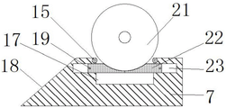
如图1所示的一种电缆盘敷设放线装置,包括两个平行设置的支撑底座7,两个所述支撑底座7的结构相同,如图3及图4所示,所述支撑底座7的一侧设有连接其顶面和底面的滚动斜面18,且支撑底座7的内部开设有贯通其顶面的容置槽17,如图5及图6所示,所述容置槽17的长度方向的两端侧顶部均设有一根平行于支撑底座7宽度方向的转动辊15,所述转动辊15的顶部与支撑底座7的顶部平齐,如图2所示,所述转动辊15的中轴线上贯穿式设有转动轴11,所述转动轴11的两端分别通过第二轴承12与支撑底座7转动连接;如图5及图6所示,所述容置槽17内对应转动辊15所在侧的侧壁上均开设有水平设置的滑动槽23,所述滑动槽23内滑动连接有承托块22;As shown in FIG. 1 , a cable reel laying and pay-off device includes two supporting
如图5及图6所示,两个所述承托块22相向设置,两个所述承托块22相向侧的上部均设有用于承托电缆盘21的承托面,且两个承托面的间距由下至上渐大,两个所述承托块22的相背侧固定有贯穿并延伸至支撑底座7外侧的第二滑动杆19,如图3及图4所示,所述支撑底座7上开设有两个连通相应滑动槽23并供相应第二滑动杆19横向滑动的横向滑孔20,所述支撑底座7上对应两个横向滑孔20的中部的位置处开设有一个纵向设置的纵向滑槽9,所述纵向滑槽9内滑动连接有一根第一滑动杆8,所述第一滑动杆8的外侧端延伸至支撑底座7的外侧,所述第一滑动杆8与两根第二滑动杆19之间分别连接有一根连接杆2,且连接杆2的两端分别对应与第一滑动杆8和第二滑动杆19铰接。As shown in FIG. 5 and FIG. 6 , the two supporting
在本实施例中,所述纵向滑槽9的横截面呈“T”形,所述第一滑动杆8的相应端呈与纵向滑槽9相适配的“T”形。纵向滑槽9与第一滑动杆8之间通过“T”形结构适配设置,可防止第一滑动杆8脱离纵向滑槽9。In this embodiment, the cross section of the longitudinal sliding
在本实施例中,如图1至图4所示,所述第一滑动杆8的外侧端固定套装有一个安装块,且该安装块的上端面上固定有一块踩踏板1。应用中,相关操作人员可通过踩下踩踏板1使得第一滑动杆8沿纵向滑槽9滑动至其底部,其操作较为方便。In this embodiment, as shown in FIGS. 1 to 4 , a mounting block is fixedly sleeved on the outer end of the first sliding rod 8 , and a
在本实施例中,如图5及图6所示,两个所述承托块22上的承托面均呈与电缆盘21的外圆底部相贴合的弧形。在电缆盘21陷入容置槽17的过程中,可通过呈弧形的承托面推动承托块22向相应的滑动槽23内移动;当第一滑动杆8向下移动时,通过连接杆2拉动两个承托块22相向移动,可通过呈弧形的承托面托起电缆盘21,满足设计要求。In this embodiment, as shown in FIG. 5 and FIG. 6 , the supporting surfaces on the two supporting
上述电缆盘敷设放线装置的具体作用过程为:The specific action process of the above-mentioned cable tray laying and pay-off device is as follows:
将电缆盘21的两个圆形侧板一一对准两个支撑底座7,并使电缆盘21的两个圆形侧板沿相应支撑底座7的滚动斜面18滚动至支撑底座7的顶面上,随后电缆盘21在支撑底座7的顶面上滚动,会掉入容置槽17内,在其过程中,电缆盘21推动承托块22向相应的滑动槽23内移动,带动两根第二滑动杆19沿横向滑孔20背向移动,通过连接杆2拉动第一滑动杆8沿纵向滑槽9上移,最终,电缆盘21的下部两侧分别贴附在相应侧的转动辊15上;然后相关操作人员手动驱动电缆盘21的两个圆形侧板在容置槽17内转动进行放线,因为在电缆盘21转动的过程中,两侧的转动辊15与电缆盘21的贴合处都会受到摩擦力的作用而同时发生转动,则电缆盘21难以在转动辊15的贴附侧找到稳定的支点,致使电缆盘21不容易从容置槽17内移出,即在放线过程中,电缆盘21能够稳定的在容置槽17内转动,有利于确保电缆盘21放线过程的稳定性;待电缆盘21放线结束后,相关操作人员踩下踩踏板1,使得第一滑动杆8沿纵向滑槽9滑动至其底部,通过连接杆2拉动两根第二滑动杆19沿横向滑孔20相向移动,带动承托块22向容置槽17内移动,在其过程中,通过承托面可顶起电缆盘21,使得电缆盘21脱离转动辊15,然后手动驱动电缆盘21滚出容置槽17即可(在其过程中,需要在滚动斜面18所在侧的转动辊15上借力,但因为电缆盘21的位置比之前高,且相关操作人员在背向滚动斜面18一侧的施力点可向下偏移,从而能够顺利在相应的转动辊15上找到支点),最后电缆盘21沿滚动斜面18滚动至地面上。Align the two circular side plates of the
实施例2Example 2
本实施例与实施例1的不同之处在于:The difference between this embodiment and
在本实施例中,如图1及图2所示,所述容置槽17内设有平行于支撑底座7宽度方向并位于承托板22的下方的从动轴3,所述从动轴3上固定套装有驱动轮16,两个所述支撑底座7的从动轴3的相向端贯穿延伸至两个支撑底座7之间并分别连接在一个双轴电机5的两侧输出端,所述双轴电机5的底部连接有固定座6,所述驱动轮16两侧的从动轴3部分均通过第一轴承10与支撑底座7转动连接。在电缆盘21位于容置槽17内时,电缆盘21的底部与驱动轮16贴合,然后通过驱动双轴电机5,可带动从动轴3转动,从而能够带动驱动轮16转动,进而能够带动电缆盘21转动,即实现电缆盘21的放线操作的电力驱动,不需要相关操作人员进行手动驱动。In this embodiment, as shown in FIG. 1 and FIG. 2 , the
在本实施例中,如图7及图8所示,两个所述承托块22上的承托面为斜面,且两个承托面关于容置槽17的竖直中心面对称设置。在电缆盘21陷入容置槽17的过程中,可通过呈斜面的承托面推动承托块22向相应的滑动槽23内移动;当第一滑动杆8向下移动时,通过连接杆2拉动两个承托块22相向移动,可通过呈斜面的承托面托起电缆盘21,满足设计要求。In this embodiment, as shown in FIGS. 7 and 8 , the supporting surfaces on the two supporting
其它同实施例1。Others are the same as in Example 1.
实施例3Example 3
本实施例与实施例2的不同之处在于:The difference between this embodiment and
在本实施例中,如图1及图2所示,所述双轴电机5的两根输出轴的自由端均同轴向式固定有供相侧从动轴3的外侧端插入的主动套筒4,且所述主动套筒4的内环侧上设有内齿圈13,所述从动轴3位于支撑底座7外侧的部分上设有与内齿圈13相适配的外齿圈14。通过对从动轴3插入主动套筒4内的深度的调节,可调节两个支撑底座7之间的距离,从而能够适应于不同长度的电缆盘21。In this embodiment, as shown in FIG. 1 and FIG. 2 , the free ends of the two output shafts of the dual-
在本实施例中,如图9及图10所示,两个所述承托块22上的承托面为斜面,且位于背向滚动斜面18的一侧的承托块22上的承托面的坡度大于另一个承托面。在电缆盘21陷入容置槽17的过程中,可通过呈斜面的承托面推动承托块22向相应的滑动槽23内移动;当第一滑动杆8向下移动时,通过连接杆2拉动两个承托块22相向移动,可通过呈斜面的承托面托起电缆盘21,同时,坡度较大的承托面对电缆盘21的承托效果高于另一个承托面,可使得电缆盘21在被顶起的同时还向滚动斜面18所在侧移动,从而能够进一步地方便实现在该侧转动辊15上找到稳定的支点,为电缆盘21从容置槽17中移出提供便利。In this embodiment, as shown in FIG. 9 and FIG. 10 , the supporting surfaces on the two supporting
其它同实施例2。Others are the same as in Example 2.
由上述内容可知,本发明结构设计巧妙可靠,可实现电缆盘的稳定放线,安全稳定性高;还可较为方便的进行电缆盘的上架和下架,有利于提高电缆敷设的效率。It can be seen from the above content that the structure design of the present invention is ingenious and reliable, which can realize the stable payout of the cable reel, and has high safety and stability; it can also conveniently carry out the racking and dismounting of the cable reel, which is beneficial to improve the efficiency of cable laying.
本技术领域中的普通技术人员应当认识到,以上的实施例仅是用来说明本发明,而并非用作为对本发明的限定,只要在本发明的实质精神范围内,对以上所述实施例的变化、变型都将落在本发明的权利要求范围内。Those skilled in the art should realize that the above embodiments are only used to illustrate the present invention, but not to limit the present invention. Changes and modifications will fall within the scope of the claims of the present invention.
Claims (3)
Priority Applications (1)
| Application Number | Priority Date | Filing Date | Title |
|---|---|---|---|
| CN202010654808.7A CN111776875B (en) | 2020-07-09 | 2020-07-09 | Cable drum lays pay-off |
Applications Claiming Priority (1)
| Application Number | Priority Date | Filing Date | Title |
|---|---|---|---|
| CN202010654808.7A CN111776875B (en) | 2020-07-09 | 2020-07-09 | Cable drum lays pay-off |
Publications (2)
| Publication Number | Publication Date |
|---|---|
| CN111776875A CN111776875A (en) | 2020-10-16 |
| CN111776875B true CN111776875B (en) | 2022-06-14 |
Family
ID=72758646
Family Applications (1)
| Application Number | Title | Priority Date | Filing Date |
|---|---|---|---|
| CN202010654808.7A Active CN111776875B (en) | 2020-07-09 | 2020-07-09 | Cable drum lays pay-off |
Country Status (1)
| Country | Link |
|---|---|
| CN (1) | CN111776875B (en) |
Families Citing this family (1)
| Publication number | Priority date | Publication date | Assignee | Title |
|---|---|---|---|---|
| CN114233927A (en) * | 2021-12-30 | 2022-03-25 | 马鞍山市盛远管道有限公司 | Adjustable auxiliary laying equipment for nodular cast iron pipes and butt-joint laying method |
Citations (5)
| Publication number | Priority date | Publication date | Assignee | Title |
|---|---|---|---|---|
| JPS63293507A (en) * | 1987-05-15 | 1988-11-30 | サーティ エス.ピー.エイ. | winch |
| CN207861577U (en) * | 2018-06-04 | 2018-09-14 | 国网湖北省电力有限公司宜昌供电公司 | Tablet bearing-type large size reel cable pay-off equipment |
| CN210211327U (en) * | 2019-07-16 | 2020-03-31 | 湖北博兴复合材料股份有限公司 | Hot forming device for automobile spare tire cover plate |
| CN210366402U (en) * | 2019-07-17 | 2020-04-21 | 江苏杜昌电力设备制造有限公司 | Automatic pay-off rack |
| CN111071852A (en) * | 2019-11-12 | 2020-04-28 | 广州市电力工程有限公司 | Movable horizontal power-assisted cable tray frame |
Family Cites Families (5)
| Publication number | Priority date | Publication date | Assignee | Title |
|---|---|---|---|---|
| FR2741611B1 (en) * | 1995-11-29 | 1999-07-23 | Woock Jean Pierre | EXTRACTABLE COIL FEEDER FOR THE SALE BY THE METER OF A FLEXIBLE PRODUCT, PARTICULARLY FILIFORM OR TUBULAR |
| CN203212111U (en) * | 2013-04-09 | 2013-09-25 | 柯里拉 | Novel cable reel base |
| CN203423463U (en) * | 2013-07-30 | 2014-02-05 | 国家电网公司 | Vertical cable pay-off seat |
| CN104085730A (en) * | 2014-07-22 | 2014-10-08 | 李刚 | Power cable pay-off table |
| CN107776941A (en) * | 2017-11-27 | 2018-03-09 | 重庆广际实业有限公司 | A kind of bundled bailing band storing unit |
-
2020
- 2020-07-09 CN CN202010654808.7A patent/CN111776875B/en active Active
Patent Citations (5)
| Publication number | Priority date | Publication date | Assignee | Title |
|---|---|---|---|---|
| JPS63293507A (en) * | 1987-05-15 | 1988-11-30 | サーティ エス.ピー.エイ. | winch |
| CN207861577U (en) * | 2018-06-04 | 2018-09-14 | 国网湖北省电力有限公司宜昌供电公司 | Tablet bearing-type large size reel cable pay-off equipment |
| CN210211327U (en) * | 2019-07-16 | 2020-03-31 | 湖北博兴复合材料股份有限公司 | Hot forming device for automobile spare tire cover plate |
| CN210366402U (en) * | 2019-07-17 | 2020-04-21 | 江苏杜昌电力设备制造有限公司 | Automatic pay-off rack |
| CN111071852A (en) * | 2019-11-12 | 2020-04-28 | 广州市电力工程有限公司 | Movable horizontal power-assisted cable tray frame |
Also Published As
| Publication number | Publication date |
|---|---|
| CN111776875A (en) | 2020-10-16 |
Similar Documents
| Publication | Publication Date | Title |
|---|---|---|
| CN207861577U (en) | Tablet bearing-type large size reel cable pay-off equipment | |
| CN110061450A (en) | Cable automatic laying system and its cable-laying gear | |
| CN113968514B (en) | A multifunctional cable pay-off device applied to municipal electric power construction | |
| CN207774448U (en) | A kind of electromechanics construction cable paying-off implement | |
| CN104716616A (en) | Novel pay-off rack | |
| CN111776875A (en) | A cable reel laying and pay-off device | |
| CN106516884A (en) | Cable take-up mechanism | |
| CN204559067U (en) | A kind of Novel pay-off stand | |
| CN111153295A (en) | An active heavy-duty cable winding machine with its own driving force | |
| CN114057009B (en) | An efficient wiring device and wiring method for outdoor cable trenches | |
| CN215885910U (en) | Portable cable reel winding and unwinding devices | |
| CN219823303U (en) | Antiwind unwrapping wire ware | |
| CN221102897U (en) | Automatic pay-off support of cable for cable laying | |
| CN204559006U (en) | Pay off rack | |
| CN221929141U (en) | Power transmission cable laying device | |
| CN220306849U (en) | Cable traction laying device | |
| CN203959487U (en) | Electric power cable unwrapping wire platform | |
| CN120016366A (en) | A cable laying device for cable trench | |
| CN217920825U (en) | Electric wire and cable pay-off rack | |
| CN115029968B (en) | Auxiliary conveying device for steel rail | |
| CN116979424A (en) | Cable laying device for electrical engineering | |
| CN116238971A (en) | A power cable retracting device | |
| CN115196409A (en) | Power supply construction is with supplementary pay-off | |
| CN220519821U (en) | Cable-former wire coil | |
| CN221700793U (en) | Paying-off device convenient for laying urban cables |
Legal Events
| Date | Code | Title | Description |
|---|---|---|---|
| PB01 | Publication | ||
| PB01 | Publication | ||
| SE01 | Entry into force of request for substantive examination | ||
| SE01 | Entry into force of request for substantive examination | ||
| GR01 | Patent grant | ||
| GR01 | Patent grant | ||
| TR01 | Transfer of patent right |
Effective date of registration: 20250619 Address after: 457000 north section of Chaoyang Road, Wenxi industry and Trade Zone, Puyang County, Puyang City, Henan Province Patentee after: Puyang Chuangye Electromechanical Engineering Co.,Ltd. Country or region after: China Address before: 238300 No.1, East longan Road, Gaoxin Avenue, longan industrial zone, Gaogou Town, Wuwei County, Wuhu City, Anhui Province Patentee before: ANHUI LINGYU CABLE TECHNOLOGY Co.,Ltd. Country or region before: China |
|
| TR01 | Transfer of patent right |