CN111760966A - An intelligent high-end digital mold production equipment - Google Patents
An intelligent high-end digital mold production equipment Download PDFInfo
- Publication number
- CN111760966A CN111760966A CN202010770066.4A CN202010770066A CN111760966A CN 111760966 A CN111760966 A CN 111760966A CN 202010770066 A CN202010770066 A CN 202010770066A CN 111760966 A CN111760966 A CN 111760966A
- Authority
- CN
- China
- Prior art keywords
- plate
- rod
- mounting
- fixedly installed
- processing
- Prior art date
- Legal status (The legal status is an assumption and is not a legal conclusion. Google has not performed a legal analysis and makes no representation as to the accuracy of the status listed.)
- Pending
Links
Images



Classifications
-
- B—PERFORMING OPERATIONS; TRANSPORTING
- B21—MECHANICAL METAL-WORKING WITHOUT ESSENTIALLY REMOVING MATERIAL; PUNCHING METAL
- B21D—WORKING OR PROCESSING OF SHEET METAL OR METAL TUBES, RODS OR PROFILES WITHOUT ESSENTIALLY REMOVING MATERIAL; PUNCHING METAL
- B21D28/00—Shaping by press-cutting; Perforating
- B21D28/24—Perforating, i.e. punching holes
- B21D28/26—Perforating, i.e. punching holes in sheets or flat parts
-
- B—PERFORMING OPERATIONS; TRANSPORTING
- B21—MECHANICAL METAL-WORKING WITHOUT ESSENTIALLY REMOVING MATERIAL; PUNCHING METAL
- B21D—WORKING OR PROCESSING OF SHEET METAL OR METAL TUBES, RODS OR PROFILES WITHOUT ESSENTIALLY REMOVING MATERIAL; PUNCHING METAL
- B21D28/00—Shaping by press-cutting; Perforating
- B21D28/24—Perforating, i.e. punching holes
- B21D28/34—Perforating tools; Die holders
-
- B—PERFORMING OPERATIONS; TRANSPORTING
- B21—MECHANICAL METAL-WORKING WITHOUT ESSENTIALLY REMOVING MATERIAL; PUNCHING METAL
- B21D—WORKING OR PROCESSING OF SHEET METAL OR METAL TUBES, RODS OR PROFILES WITHOUT ESSENTIALLY REMOVING MATERIAL; PUNCHING METAL
- B21D37/00—Tools as parts of machines covered by this subclass
- B21D37/16—Heating or cooling
-
- B—PERFORMING OPERATIONS; TRANSPORTING
- B21—MECHANICAL METAL-WORKING WITHOUT ESSENTIALLY REMOVING MATERIAL; PUNCHING METAL
- B21D—WORKING OR PROCESSING OF SHEET METAL OR METAL TUBES, RODS OR PROFILES WITHOUT ESSENTIALLY REMOVING MATERIAL; PUNCHING METAL
- B21D43/00—Feeding, positioning or storing devices combined with, or arranged in, or specially adapted for use in connection with, apparatus for working or processing sheet metal, metal tubes or metal profiles; Associations therewith of cutting devices
- B21D43/02—Advancing work in relation to the stroke of the die or tool
Landscapes
- Engineering & Computer Science (AREA)
- Mechanical Engineering (AREA)
- Perforating, Stamping-Out Or Severing By Means Other Than Cutting (AREA)
Abstract
Description
技术领域technical field
本发明属于模具生产领域,涉及数字化加工技术,具体是一种智能高端数字化模具生产设备。The invention belongs to the field of mold production and relates to digital processing technology, in particular to an intelligent high-end digital mold production equipment.
背景技术Background technique
模具的数字化生产已经成为新的发展趋势,模具生产之前需要对生产模具所用的原材料板材进行冲孔,从而方便模具的生产,传统的设备需要人工手动移动板材来实现冲孔头对板材多个位置进行冲孔,费时费力,效率低下,而且人工操作较为危险。The digital production of molds has become a new development trend. Before mold production, it is necessary to punch the raw material plates used in the production of molds, so as to facilitate the production of molds. Traditional equipment needs to manually move the plates manually to achieve multiple positions of the punching head on the plate. Punching is time-consuming and labor-intensive, inefficient, and manual operation is more dangerous.
公告号为CN108655764A的中国专利揭示了一种高端数字化模具生产设备,该设备在初始状态时,驱动电机、滑动电机、驱转电机、输送机、高速电机、转动电机、顶块后端壁内的电机和伸缩气缸处于停止工作状态,从而使上述结构在初始状态时位于初始位置,可以在后续工作中进行调整,有效提高设备的工作协调性;但是该设备没有设置升降机构,导致加工件放料和取料的过程不方便。The Chinese patent with Announcement No. CN108655764A discloses a high-end digital mold production equipment. In the initial state of the equipment, the driving motor, the sliding motor, the driving motor, the conveyor, the high-speed motor, the rotating motor, and the The motor and the telescopic cylinder are in the stopped working state, so that the above structure is in the initial position in the initial state, which can be adjusted in the follow-up work, which effectively improves the work coordination of the equipment; And the process of taking the material is inconvenient.
发明内容SUMMARY OF THE INVENTION
本发明的目的在于提供一种智能高端数字化模具生产设备;The purpose of the present invention is to provide a kind of intelligent high-end digital mold production equipment;
本发明需要解决的技术问题为:The technical problem that the present invention needs to solve is:
(1)如何提供一种可智能数字化控制钻头位置的模具生产设备;(1) How to provide a mold production equipment that can intelligently digitally control the position of the drill bit;
(2)如何提供一种便于放料和取料的模具生产设备。(2) How to provide a mold production equipment that is convenient for discharging and reclaiming.
本发明的目的可以通过以下技术方案实现:The object of the present invention can be realized through the following technical solutions:
一种智能高端数字化模具生产设备,包括工作台以及安装在安装台底面的四个底座,底座底部与地面连接,所述工作台底面固定安装有第一固定板与第二固定板,所述工作台顶面固定安装有驱动电机,所述驱动电机输出端通过电机轴固定安装有双向螺纹杆,所述双向螺纹杆远离驱动电机的一端穿过第二固定板并通过轴承与第一固定板活动连接,所述双向螺纹杆外表面螺纹连接有两个相对称的螺纹套,所述工作台顶部固定安装有两个相对称的直板,两个所述直板相靠近的侧面之间固定安装有滑杆,所述滑杆外表面活动连接有两个相对称的滑套,两个所述滑套相靠近的一端之间固定安装有第一弹簧,所述滑套底部与螺纹套顶部之间固定安装有固定杆,所述工作台顶部固定安装有两个相对称的连接柱,所述连接柱外表面活动连接有活动套,所述活动套底部与工作台顶面之间固定安装有第二弹簧,所述活动套侧面与滑套顶面之间铰接有连接杆,两个所述活动套顶部之间固定安装升降板,所述升降板与连接柱的外表面活动连接;An intelligent high-end digital mold production equipment includes a workbench and four bases installed on the bottom surface of the installation platform, the bottom of the bases is connected to the ground, and the bottom surface of the workbench is fixedly installed with a first fixing plate and a second fixing plate, and the work A drive motor is fixedly installed on the top surface of the table, the output end of the drive motor is fixedly installed with a bidirectional threaded rod through the motor shaft, and the end of the bidirectional threaded rod away from the driving motor passes through the second fixing plate and moves with the first fixing plate through bearings The outer surface of the two-way threaded rod is threadedly connected with two symmetrical threaded sleeves, two symmetrical straight plates are fixedly installed on the top of the workbench, and a sliding plate is fixedly installed between the adjacent sides of the two straight plates. A rod, the outer surface of the sliding rod is movably connected with two symmetrical sliding sleeves, a first spring is fixedly installed between the close ends of the two sliding sleeves, and the bottom of the sliding sleeve and the top of the threaded sleeve are fixed between A fixed rod is installed, two symmetrical connecting columns are fixedly installed on the top of the workbench, a movable sleeve is movably connected to the outer surface of the connecting column, and a second movable sleeve is fixedly installed between the bottom of the movable sleeve and the top surface of the workbench. a spring, a connecting rod is hinged between the side surface of the movable sleeve and the top surface of the sliding sleeve, a lifting plate is fixedly installed between the tops of the two movable sleeves, and the lifting plate is movably connected with the outer surface of the connecting column;
所述工作台顶面固定安装有四个支撑柱,四个所述支撑柱的顶部之间固定安装有加工箱体,所述加工箱体内底壁开设有矩形开口,所述加工箱体两个内侧壁均固定安装有导轨,两个所述导轨相靠近的一侧均活动连接有滑块,两个所述滑块相靠近的侧面之间固定安装有安装杆,所述安装杆外表面活动连接有两个相对称的安装套,所述安装套底部固定安装有安装块,两个所述安装块的底部之间固定安装有安装板,所述安装板底部固定安装有气缸,所述气缸输出端固定安装有冲头,所述冲头底部穿过矩形开口并延伸至加工箱体的外部;Four support columns are fixedly installed on the top surface of the worktable, and a processing box is fixedly installed between the tops of the four support columns. The bottom wall of the processing box is provided with a rectangular opening, and the two Guide rails are fixedly installed on the inner side walls, sliding blocks are movably connected to the sides of the two guide rails that are close to each other, and mounting rods are fixedly installed between the two sides that are close to the sliding blocks, and the outer surfaces of the mounting rods are movable. Two symmetrical mounting sleeves are connected, a mounting block is fixedly installed at the bottom of the mounting sleeve, a mounting plate is fixedly installed between the bottoms of the two mounting blocks, and a cylinder is fixedly installed at the bottom of the mounting plate, and the cylinder is fixedly installed. A punch is fixedly installed at the output end, and the bottom of the punch passes through the rectangular opening and extends to the outside of the processing box;
左侧的所述滑块的底部固定安装有竖板,所述竖板与安装板相靠近的侧面之间固定安装有第一电动推杆,所述竖板侧面设置有第一位移传感器,右侧的所述滑块的背面与加工箱体背面的内壁之间固定安装有第二电动推杆,所述安装板顶部设置有第二位移传感器,所述加工箱体正面设置有处理器与PLC控制器;A vertical plate is fixedly installed at the bottom of the slider on the left side, a first electric push rod is fixedly installed between the vertical plate and the side adjacent to the installation plate, and a first displacement sensor is arranged on the side of the vertical plate. A second electric push rod is fixedly installed between the back of the slider on the side and the inner wall of the back of the processing box, a second displacement sensor is arranged on the top of the mounting plate, and a processor and a PLC are arranged on the front of the processing box. controller;
第一位移传感器、第二位移传感器的输出端与处理器的输入端电性连接,处理器的输出端与PLC控制器的输入端电性连接,PLC控制器的输出端与驱动电机、气缸、第一电动推杆、第二电动推杆的输入端电性连接。The output ends of the first displacement sensor and the second displacement sensor are electrically connected with the input end of the processor, the output end of the processor is electrically connected with the input end of the PLC controller, and the output end of the PLC controller is electrically connected with the driving motor, the cylinder, The input ends of the first electric push rod and the second electric push rod are electrically connected.
进一步地,所述加工箱体侧面固定安装有风箱,所述风箱与加工箱体相靠近的两个内侧壁之间贯穿连通有安装管,所述安装管内壁之间固定安装有风机,所述风箱内顶壁固定连通有出风管,所述风箱内侧壁之间固定安装有滤网,所述风箱内底壁固定连通有排屑管,所述排屑管底部设置有阀门。Further, a bellows is fixedly installed on the side of the processing box, an installation pipe is communicated through between the two inner side walls of the bellows and the adjacent inner walls of the processing box, and a fan is fixedly installed between the inner walls of the installation pipe. An air outlet pipe is fixedly connected to the inner top wall of the bellows, a filter screen is fixedly installed between the inner side walls of the bellows, a chip discharge pipe is fixedly connected to the inner bottom wall of the bellows, and a valve is provided at the bottom of the chip discharge pipe.
进一步地,所述第一弹簧套接在滑杆的外表面,且第一弹簧内圈与滑杆外表面之间留有间隙。Further, the first spring is sleeved on the outer surface of the sliding rod, and a gap is left between the inner ring of the first spring and the outer surface of the sliding rod.
进一步地,所述第二弹簧套接在连接柱的外表面,且第二弹簧内圈与连接柱外表面之间留有间隙。Further, the second spring is sleeved on the outer surface of the connecting column, and a gap is left between the inner ring of the second spring and the outer surface of the connecting column.
进一步地,所述加工箱体的内侧壁与内顶壁均固定安装有孔木吸音板,所述孔木吸音板表面设有多个吸音孔,所述孔木吸音板内部设有吸音毡。Further, a perforated wood sound-absorbing board is fixedly installed on the inner side wall and the inner top wall of the processing box, a plurality of sound-absorbing holes are arranged on the surface of the perforated wooden sound-absorbing board, and a sound-absorbing felt is arranged inside the perforated wood sound-absorbing board.
进一步地,所述升降板顶面设有多个夹紧块,所述升降板顶面开设有加工放置槽,所述加工放置槽内底壁开设有冲孔槽,所述冲孔槽底部贯穿至升降板底面。Further, the top surface of the lifting plate is provided with a plurality of clamping blocks, the top surface of the lifting plate is provided with a processing placement slot, and the inner bottom wall of the processing placement slot is provided with a punching slot, and the bottom of the punching slot penetrates through the bottom wall. to the bottom of the lift plate.
进一步地,所述工作台顶面与底面之间开设有卡槽,所述卡槽内壁与固定杆外表面活动连接。Further, a clamping slot is opened between the top surface and the bottom surface of the worktable, and the inner wall of the clamping slot is movably connected with the outer surface of the fixing rod.
进一步地,一种智能高端数字化模具生产设备,该装置的使用方法包括如下步骤:Further, an intelligent high-end digital mold production equipment, the use method of the device includes the following steps:
第一步:启动驱动电机正转带动双向螺纹杆正转,使两个螺纹套在双向螺纹杆上互相靠近,从而带动两个滑套互相靠近,通过连接杆控制升降板位置下降,当位置下降至上料高度后,关闭驱动电机;Step 1: Start the forward rotation of the drive motor to drive the two-way threaded rod to rotate forward, so that the two threaded sleeves are close to each other on the two-way threaded rod, thereby driving the two sliding sleeves to approach each other, and the position of the lifting plate is controlled by the connecting rod. After reaching the feeding height, turn off the drive motor;
第二步:将待加工的模具板材放置在加工放置槽内,并利用多个夹紧块对板材进行夹紧,启动驱动电机反转带动双向螺纹杆反向转动,从而控制两个螺纹套互相分离,通过连接杆将升降板顶起,当升降板位置上升至加工高度时,关闭驱动电机;Step 2: Place the mold plate to be processed in the processing slot, and use multiple clamping blocks to clamp the plate, start the drive motor to reverse the direction to drive the two-way threaded rod to rotate in the reverse direction, so as to control the two threaded sleeves to mutually Separation, lift up the lift plate through the connecting rod, when the position of the lift plate rises to the processing height, turn off the drive motor;
第三步:将导轨设为X轴、安装杆设为Y轴,通过PLC控制器启动第二电动推杆伸出,推动滑块在导轨上沿X轴滑动,第一传感器实时检测滑块的X轴位移值,并将X轴位移值输送至处理器,处理器对X轴位移值进行处理,并在X轴位移值达到设定值时向PLC控制器发送中止信号,PLC控制器在接收到中止信号后关闭第二电动推杆,通过PLC控制器启动第一电动推杆伸出,推动安装板在Y轴上移动,第二传感器实时检测安装板的Y轴位移值,并将Y轴位移值输送至处理器,处理器对Y轴位移值进行处理,并在Y轴位移值达到设定值时向PLC控制器发送中止信号,PLC控制器在接收到中止信号后关闭第一电动推杆,从而使得冲头位于板材待冲孔位置的正上方;Step 3: Set the guide rail as the X axis and the installation rod as the Y axis, start the second electric push rod to extend through the PLC controller, push the slider to slide along the X axis on the guide rail, and the first sensor detects the movement of the slider in real time. The X-axis displacement value is sent to the processor. The processor processes the X-axis displacement value and sends a stop signal to the PLC controller when the X-axis displacement value reaches the set value. The PLC controller receives the After the stop signal is reached, the second electric push rod is turned off, the first electric push rod is started to extend through the PLC controller, and the mounting plate is pushed to move on the Y axis. The second sensor detects the Y axis displacement value of the mounting plate in real time, and the Y axis is moved. The displacement value is sent to the processor, the processor processes the Y-axis displacement value, and sends a stop signal to the PLC controller when the Y-axis displacement value reaches the set value, and the PLC controller turns off the first electric pusher after receiving the stop signal. rod so that the punch is directly above the position where the sheet is to be punched;
第四步:启动气缸伸出,推动冲头迅速下移,利用冲头对板材进行冲孔加工,启动风机对加工箱体内部进行散热,并将冲孔加工产生的碎屑吸入风箱内,碎屑在滤网的阻隔下被留在风箱内部;Step 4: Start the cylinder to extend, push the punch down quickly, use the punch to punch the plate, start the fan to dissipate heat from the inside of the processing box, and suck the chips generated by the punching process into the bellows, crushing them. The chips are kept inside the bellows under the barrier of the filter screen;
第五步:冲孔加工完成后,通过PLC控制器控制气缸收缩,冲头与板材分离后,启动驱动电机正转,通过双向螺纹杆、螺纹套、滑套以及连接杆控制升降板位置下降,将板材从加工放置槽中取出,完成整个冲孔加工过程。Step 5: After the punching process is completed, control the cylinder contraction through the PLC controller. After the punch is separated from the plate, start the driving motor to rotate forward, and control the position of the lifting plate to descend through the two-way threaded rod, threaded sleeve, sliding sleeve and connecting rod. Take the sheet out of the machining slot to complete the entire punching process.
本发明的有益效果:本发明具备下述有益效果:Beneficial effects of the present invention: the present invention has the following beneficial effects:
1、通过设置的第一位移传感器、第二位移传感器、第一电动推杆、第二电动推杆、处理器以及PLC控制器等结构可以对安装板在XY轴坐标系上的位置进行控制调节,从而不需要人工手动对板材进行调整,即可对板材的多个冲孔位置进行冲孔加工,操作简单方便,提高了设备的加工效率;1. The position of the mounting plate on the XY coordinate system can be controlled and adjusted by the first displacement sensor, the second displacement sensor, the first electric push rod, the second electric push rod, the processor and the PLC controller. , so that there is no need to manually adjust the plate, the punching process can be performed on multiple punching positions of the plate, the operation is simple and convenient, and the processing efficiency of the equipment is improved;
2、通过设置的驱动电机、双向螺纹杆、螺纹套、滑套以及连接杆等结构可以控制升降板上升与下降,从而在上料与下料时直接控制升降板下降至放料高度,在加工时控制升降板上升至加工高度,从而可方便了板材的放料与取料过程;2. The rise and fall of the lifting plate can be controlled by the set drive motor, bidirectional threaded rod, threaded sleeve, sliding sleeve and connecting rod, so that the lifting plate can be directly controlled to descend to the discharge height during feeding and unloading. At the same time, the lifting plate is controlled to rise to the processing height, which can facilitate the process of unloading and reclaiming the plate;
3、通过第一弹簧与第二弹簧等结构可以对升降板提供减震缓冲效果,在加工时,升降板上的板材受到钻头冲击,导致第二弹簧收缩,活动套位置下降,通过连接杆挤压第一弹簧收缩,从而利用第一弹簧与第二弹簧同时对升降板起到减震缓冲的效果;3. The structure of the first spring and the second spring can provide shock absorption and buffering effect to the lifting plate. During processing, the plate on the lifting plate is impacted by the drill bit, causing the second spring to shrink, the position of the movable sleeve to drop, and squeeze through the connecting rod. Press the first spring to contract, so as to use the first spring and the second spring to play a shock-absorbing and buffering effect on the lifting plate at the same time;
4、通过设置的风机可以对加工箱体、冲头进行风冷降温,同时将冲孔产生的碎屑吸入风箱内部,在滤网的阻隔下,碎屑被留在风箱内部存储,在加工完成后可打开排屑管的阀门将碎屑集中取出,避免了碎屑四处飞溅,对工作人员的安全产生威胁。4. The processing box and punch can be cooled by air through the set fan, and the debris generated by punching can be sucked into the bellows. Under the barrier of the filter screen, the debris is stored in the bellows, and the processing is completed. Afterwards, the valve of the chip discharge pipe can be opened to take out the chips in a centralized manner, so as to avoid the chips from splashing around and threatening the safety of the staff.
附图说明Description of drawings
为了便于本领域技术人员理解,下面结合附图对本发明作进一步的说明。In order to facilitate the understanding of those skilled in the art, the present invention will be further described below with reference to the accompanying drawings.
图1为本发明结构主视图;Fig. 1 is the front view of the structure of the present invention;
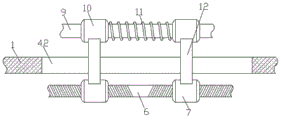
图2为本发明图1中A处结构放大示意图;Fig. 2 is the enlarged schematic diagram of the structure at place A in Fig. 1 of the present invention;
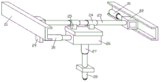
图3为本发明本发明加工箱体结构主视剖视图;Figure 3 is a front cross-sectional view of the processing box structure of the present invention;
图4为本发明导轨、安装杆与安装板的结构侧视图;Fig. 4 is the structural side view of the guide rail, the mounting rod and the mounting plate of the present invention;
图5为本发明升降板的结构侧视图;Fig. 5 is the structural side view of the lifting plate of the present invention;
图6为本发明工作台结构主视剖视图。6 is a front cross-sectional view of the structure of the workbench of the present invention.
图中:1、工作台;2、底座;3、第一固定板;4、第二固定板;5、驱动电机;6、双向螺纹杆;7、螺纹套;8、直板;9、滑杆;10、滑套;11、第一弹簧;12、固定杆;13、连接柱;14、活动套;15、第二弹簧;16、连接杆;17、升降板;18、支撑柱;19、加工箱体;20、矩形开口;21、导轨;22、滑块;23、安装杆;24、安装套;25、安装块;26、安装板;27、气缸;28、冲头;29、竖板;30、第一电动推杆;31、第二电动推杆;32、风箱;33、安装管;34、风机;35、出风管;36、滤网;37、排屑管;38、孔木吸音板;39、夹紧块;40、加工放置槽;41、冲孔槽;42、卡槽。In the figure: 1. Workbench; 2. Base; 3. First fixing plate; 4. Second fixing plate; 5. Driving motor; 6. Two-way threaded rod; 7. Threaded sleeve; 8. Straight plate; ; 10, sliding sleeve; 11, first spring; 12, fixed rod; 13, connecting column; 14, movable sleeve; 15, second spring; 16, connecting rod; 17, lifting plate; 18, supporting column; 19, Processing box; 20, rectangular opening; 21, guide rail; 22, slider; 23, mounting rod; 24, mounting sleeve; 25, mounting block; 26, mounting plate; 27, cylinder; 28, punch; 29, vertical plate; 30, the first electric push rod; 31, the second electric push rod; 32, the bellows; 33, the installation pipe; 34, the fan; 35, the air outlet pipe; 36, the filter screen; 37, the chip removal pipe; 38, Hole wood sound-absorbing board; 39, clamping block; 40, processing placement slot; 41, punching slot; 42, card slot.
具体实施方式Detailed ways
下面将结合实施例对本发明的技术方案进行清楚、完整地描述,显然,所描述的实施例仅仅是本发明一部分实施例,而不是全部的实施例。基于本发明中的实施例,本领域普通技术人员在没有作出创造性劳动前提下所获得的所有其它实施例,都属于本发明保护的范围。The technical solutions of the present invention will be clearly and completely described below with reference to the embodiments. Obviously, the described embodiments are only a part of the embodiments of the present invention, rather than all the embodiments. Based on the embodiments of the present invention, all other embodiments obtained by those of ordinary skill in the art without creative efforts shall fall within the protection scope of the present invention.
如图1-6所示,一种智能高端数字化模具生产设备,包括工作台1以及安装在安装台底面的四个底座2,底座2底部与地面连接,所述工作台1顶面与底面之间开设有卡槽42,所述卡槽42内壁与固定杆12外表面活动连接,卡槽42用于对固定杆12进行限位,保证固定杆12只能在左、右方向上移动,所述工作台1底面固定安装有第一固定板3与第二固定板4,所述工作台1底面固定安装有驱动电机5,驱动电机5用于驱动双向螺纹杆6转动,所述驱动电机5输出端通过电机轴固定安装有双向螺纹杆6,双向螺纹杆6用于控制两个螺纹套7靠近与分开,所述双向螺纹杆6远离驱动电机5的一端穿过第二固定板4并通过轴承与第一固定板3活动连接,所述双向螺纹杆6外表面螺纹连接有两个相对称的螺纹套7,所述工作台1顶部固定安装有两个相对称的直板8,两个所述直板8相靠近的侧面之间固定安装有滑杆9,所述滑杆9外表面活动连接有两个相对称的滑套10,两个所述滑套10相靠近的一端之间固定安装有第一弹簧11,所述第一弹簧11套接在滑杆9的外表面,且第一弹簧11内圈与滑杆9外表面之间留有间隙,避免第一弹簧11在伸缩时与滑杆9外表面相接触,产生不必要的摩擦,减轻设备零部件的磨损,所述滑套10底部与螺纹套7顶部之间固定安装有固定杆12,通过固定杆12使滑套10能够与螺纹套7同步移动,所述工作台1顶部固定安装有两个相对称的连接柱13,所述连接柱13外表面活动连接有活动套14,连接柱13与活动套14用于对升降板17进行限位,所述活动套14底部与工作台1顶面之间固定安装有第二弹簧15,所述第二弹簧15套接在连接柱13的外表面,且第二弹簧15内圈与连接柱13外表面之间留有间隙,避免第二弹簧15在伸缩时与连接柱13外表面相接触,产生不必要的摩擦,减轻设备零部件的磨损,第二弹簧15用于对升降板17提供二级减震效果,所述活动套14侧面与滑套10顶面之间铰接有连接杆16,两个所述活动套14顶部之间固定安装升降板17,所述升降板17与连接柱13的外表面活动连接,所述升降板17顶面设有多个夹紧块39,所述升降板17顶面开设有加工放置槽40,用于放置加工板材,所述加工放置槽40内底壁开设有冲孔槽41,所述冲孔槽41底部贯穿至升降板17底面;As shown in Figure 1-6, an intelligent high-end digital mold production equipment includes a workbench 1 and four bases 2 installed on the bottom surface of the installation platform. The bottom of the base 2 is connected to the ground, and the top surface and the bottom surface of the workbench 1 are connected There is a card slot 42, the inner wall of the card slot 42 is movably connected with the outer surface of the fixed
所述工作台1顶面固定安装有四个支撑柱18,四个所述支撑柱18的顶部之间固定安装有加工箱体19,所述加工箱体19内底壁开设有矩形开口20,所述加工箱体19两个内侧壁均固定安装有导轨21,两个所述导轨21相靠近的一侧均活动连接有滑块22,两个所述滑块22相靠近的侧面之间固定安装有安装杆23,所述安装杆23外表面活动连接有两个相对称的安装套24,所述安装套24底部固定安装有安装块25,两个所述安装块25的底部之间固定安装有安装板26,所述安装板26底部固定安装有气缸27,气缸27推动冲头28快速伸出,对板材进行冲孔加工,所述气缸27输出端固定安装有冲头28,所述冲头28底部穿过矩形开口20并延伸至加工箱体19的外部,所述加工箱体19侧面固定安装有风箱32,风箱32用于对冲孔产生的碎屑进行收集,所述风箱32与加工箱体19相靠近的两个内侧壁之间贯穿连通有安装管33,所述安装管33内壁之间固定安装有风机34,风机34用于对冲头28进行风冷散热,所述风箱32内顶壁固定连通有出风管35,所述风箱32内侧壁之间固定安装有滤网36,滤网36用于阻隔碎屑,将碎屑留在风箱32内进行存放,所述风箱32内底壁固定连通有排屑管37,所述排屑管37底部设置有阀门,加工完成后可打开阀门,将风箱32内的碎屑通过排屑管37排出,所述加工箱体19的内侧壁与内顶壁均固定安装有孔木吸音板38,所述孔木吸音板38表面设有多个吸音孔,所述孔木吸音板38内部设有吸音毡,孔木吸音板38用于吸收冲孔加工时产生的噪音,达到隔音降噪的目的;Four
左侧的所述滑块22的底部固定安装有竖板29,所述竖板29与安装板26相靠近的侧面之间固定安装有第一电动推杆30,通过第一电动推杆30伸出可调节安装套24在安装杆23上的相对位置,所述竖板29侧面设置有第一位移传感器,右侧的所述滑块22的背面与加工箱体19背面的内壁之间固定安装有第二电动推杆31,通过第二电动推杆31伸出可调节滑块22在滑轨上的相对位置,所述安装板26顶部设置有第二位移传感器,所述加工箱体19正面设置有处理器与PLC控制器;A
第一位移传感器、第二位移传感器的输出端与处理器的输入端电性连接,处理器的输出端与PLC控制器的输入端电性连接,PLC控制器的输出端与驱动电机5、气缸27、第一电动推杆30、第二电动推杆31的输入端电性连接。The output ends of the first displacement sensor and the second displacement sensor are electrically connected with the input end of the processor, the output end of the processor is electrically connected with the input end of the PLC controller, and the output end of the PLC controller is electrically connected with the drive motor 5 and the cylinder. 27. The input ends of the first
第一步:启动驱动电机5正转带动双向螺纹杆6正转,使两个螺纹套7在双向螺纹杆6上互相靠近,从而带动两个滑套10互相靠近,通过连接杆16控制升降板17位置下降,当位置下降至上料高度后,关闭驱动电机5;The first step: start the driving motor 5 to rotate forward to drive the two-way threaded
第二步:将待加工的模具板材放置在加工放置槽40内,并利用多个夹紧块39对板材进行夹紧,启动驱动电机5反转带动双向螺纹杆6反向转动,从而控制两个螺纹套7互相分离,通过连接杆16将升降板17顶起,当升降板17位置上升至加工高度时,关闭驱动电机5;The second step: place the mold plate to be processed in the
第三步:将导轨21设为X轴、安装杆23设为Y轴,通过PLC控制器启动第二电动推杆31伸出,推动滑块22在导轨21上沿X轴滑动,第一传感器实时检测滑块22的X轴位移值,并将X轴位移值输送至处理器,处理器对X轴位移值进行处理,并在X轴位移值达到设定值时向PLC控制器发送中止信号,PLC控制器在接收到中止信号后关闭第二电动推杆31,通过PLC控制器启动第一电动推杆30伸出,推动安装板26在Y轴上移动,第二传感器实时检测安装板26的Y轴位移值,并将Y轴位移值输送至处理器,处理器对Y轴位移值进行处理,并在Y轴位移值达到设定值时向PLC控制器发送中止信号,PLC控制器在接收到中止信号后关闭第一电动推杆30,从而使得冲头28位于板材待冲孔位置的正上方;The third step: set the guide rail 21 as the X axis and the mounting
第四步:启动气缸27伸出,推动冲头28迅速下移,利用冲头28对板材进行冲孔加工,启动风机34对加工箱体19内部进行散热,并将冲孔加工产生的碎屑吸入风箱32内,碎屑在滤网36的阻隔下被留在风箱32内部;The fourth step: start the
第五步:冲孔加工完成后,通过PLC控制器控制气缸27收缩,冲头28与板材分离后,启动驱动电机5正转,通过双向螺纹杆6、螺纹套7、滑套10以及连接杆16控制升降板17位置下降,将板材从加工放置槽40中取出,完成整个冲孔加工过程。Step 5: After the punching process is completed, control the
1、通过设置的第一位移传感器、第二位移传感器、第一电动推杆、第二电动推杆、处理器以及PLC控制器等结构可以对安装板在XY轴坐标系上的位置进行控制调节,从而不需要人工手动对板材进行调整,即可对板材的多个冲孔位置进行冲孔加工,操作简单方便,提高了设备的加工效率;1. The position of the mounting plate on the XY coordinate system can be controlled and adjusted by the first displacement sensor, the second displacement sensor, the first electric push rod, the second electric push rod, the processor and the PLC controller. , so that there is no need to manually adjust the plate, the punching process can be performed on multiple punching positions of the plate, the operation is simple and convenient, and the processing efficiency of the equipment is improved;
2、通过设置的驱动电机、双向螺纹杆、螺纹套、滑套以及连接杆等结构可以控制升降板上升与下降,从而在上料与下料时直接控制升降板下降至放料高度,在加工时控制升降板上升至加工高度,从而可方便了板材的放料与取料过程;2. The rise and fall of the lifting plate can be controlled by the set drive motor, bidirectional threaded rod, threaded sleeve, sliding sleeve and connecting rod, so that the lifting plate can be directly controlled to descend to the discharge height during feeding and unloading. At the same time, the lifting plate is controlled to rise to the processing height, which can facilitate the process of unloading and reclaiming the plate;
3、通过第一弹簧与第二弹簧等结构可以对升降板提供减震缓冲效果,在加工时,升降板上的板材受到钻头冲击,导致第二弹簧收缩,活动套位置下降,通过连接杆挤压第一弹簧收缩,从而利用第一弹簧与第二弹簧同时对升降板起到减震缓冲的效果;3. The structure of the first spring and the second spring can provide shock absorption and buffering effect to the lifting plate. During processing, the plate on the lifting plate is impacted by the drill bit, causing the second spring to shrink, the position of the movable sleeve to drop, and squeeze through the connecting rod. Press the first spring to contract, so as to use the first spring and the second spring to play a shock-absorbing and buffering effect on the lifting plate at the same time;
4、通过设置的风机可以对加工箱体、冲头进行风冷降温,同时将冲孔产生的碎屑吸入风箱内部,在滤网的阻隔下,碎屑被留在风箱内部存储,在加工完成后可打开排屑管的阀门将碎屑集中取出,避免了碎屑四处飞溅,对工作人员的安全产生威胁。4. The processing box and punch can be cooled by air through the set fan, and the debris generated by punching can be sucked into the bellows. Under the barrier of the filter screen, the debris is stored in the bellows, and the processing is completed. Afterwards, the valve of the chip discharge pipe can be opened to take out the chips in a centralized manner, so as to avoid the chips from splashing around and threatening the safety of the staff.
该文中出现的电器元件均与外界的主控器及220V市电电连接,并且主控器可为计算机等起到控制的常规已知设备。The electrical components appearing in this article are all connected with the external main controller and 220V mains, and the main controller can be a conventional known device controlled by a computer or the like.
需要说明的是,在本文中,诸如第一和第二等之类的关系术语仅仅用来将一个实体或者操作与另一个实体或操作区分开来,而不一定要求或者暗示这些实体或操作之间存在任何这种实际的关系或者顺序。而且,术语“包括”、“包含”或者其任何其他变体意在涵盖非排他性的包含,从而使得包括一系列要素的过程、方法、物品或者设备不仅包括那些要素,而且还包括没有明确列出的其他要素,或者是还包括为这种过程、方法、物品或者设备所固有的要素。It should be noted that, in this document, relational terms such as first and second are only used to distinguish one entity or operation from another entity or operation, and do not necessarily require or imply any relationship between these entities or operations. any such actual relationship or sequence exists. Moreover, the terms "comprising", "comprising" or any other variation thereof are intended to encompass a non-exclusive inclusion such that a process, method, article or device that includes a list of elements includes not only those elements, but also includes not explicitly listed or other elements inherent to such a process, method, article or apparatus.
尽管已经示出和描述了本发明的实施例,对于本领域的普通技术人员而言,可以理解在不脱离本发明的原理和精神的情况下可以对这些实施例进行多种变化、修改、替换和变型,本发明的范围由所附权利要求及其等同物限定。Although embodiments of the present invention have been shown and described, it will be understood by those skilled in the art that various changes, modifications, and substitutions can be made in these embodiments without departing from the principle and spirit of the invention and modifications, the scope of the present invention is defined by the appended claims and their equivalents.
Claims (8)
Priority Applications (1)
| Application Number | Priority Date | Filing Date | Title |
|---|---|---|---|
| CN202010770066.4A CN111760966A (en) | 2020-08-04 | 2020-08-04 | An intelligent high-end digital mold production equipment |
Applications Claiming Priority (1)
| Application Number | Priority Date | Filing Date | Title |
|---|---|---|---|
| CN202010770066.4A CN111760966A (en) | 2020-08-04 | 2020-08-04 | An intelligent high-end digital mold production equipment |
Publications (1)
| Publication Number | Publication Date |
|---|---|
| CN111760966A true CN111760966A (en) | 2020-10-13 |
Family
ID=72728908
Family Applications (1)
| Application Number | Title | Priority Date | Filing Date |
|---|---|---|---|
| CN202010770066.4A Pending CN111760966A (en) | 2020-08-04 | 2020-08-04 | An intelligent high-end digital mold production equipment |
Country Status (1)
| Country | Link |
|---|---|
| CN (1) | CN111760966A (en) |
Cited By (2)
| Publication number | Priority date | Publication date | Assignee | Title |
|---|---|---|---|---|
| CN113075358A (en) * | 2021-03-17 | 2021-07-06 | 广西建宏工程科技有限公司 | Be used for building detection control instrument |
| CN117696817A (en) * | 2024-02-05 | 2024-03-15 | 山西天宝集团有限公司 | Intelligent automatic rotary workbench for forging new energy wind power generation flange and method thereof |
Citations (6)
| Publication number | Priority date | Publication date | Assignee | Title |
|---|---|---|---|---|
| KR101228541B1 (en) * | 2012-10-02 | 2013-02-01 | 주식회사 대동강업 | Stop shock backlash control roll system |
| CN103071711A (en) * | 2012-12-14 | 2013-05-01 | 浙江天齐电气有限公司 | Precision movable numerical control system for distribution box |
| CN208712581U (en) * | 2018-08-15 | 2019-04-09 | 海宁新越建设有限公司 | A kind of construction site construction steel plate bending processing unit (plant) |
| CN208944937U (en) * | 2018-08-21 | 2019-06-07 | 天津诺瑞信精密电子有限公司 | Guide structure for punching tooling |
| CN210547353U (en) * | 2019-07-31 | 2020-05-19 | 江门市泰林模具有限公司 | Gasket locating hole processingequipment |
| CN211102929U (en) * | 2019-11-29 | 2020-07-28 | 南京创品数控技术有限公司 | Workstation of unloading of being convenient for digit control machine tool |
-
2020
- 2020-08-04 CN CN202010770066.4A patent/CN111760966A/en active Pending
Patent Citations (6)
| Publication number | Priority date | Publication date | Assignee | Title |
|---|---|---|---|---|
| KR101228541B1 (en) * | 2012-10-02 | 2013-02-01 | 주식회사 대동강업 | Stop shock backlash control roll system |
| CN103071711A (en) * | 2012-12-14 | 2013-05-01 | 浙江天齐电气有限公司 | Precision movable numerical control system for distribution box |
| CN208712581U (en) * | 2018-08-15 | 2019-04-09 | 海宁新越建设有限公司 | A kind of construction site construction steel plate bending processing unit (plant) |
| CN208944937U (en) * | 2018-08-21 | 2019-06-07 | 天津诺瑞信精密电子有限公司 | Guide structure for punching tooling |
| CN210547353U (en) * | 2019-07-31 | 2020-05-19 | 江门市泰林模具有限公司 | Gasket locating hole processingequipment |
| CN211102929U (en) * | 2019-11-29 | 2020-07-28 | 南京创品数控技术有限公司 | Workstation of unloading of being convenient for digit control machine tool |
Cited By (3)
| Publication number | Priority date | Publication date | Assignee | Title |
|---|---|---|---|---|
| CN113075358A (en) * | 2021-03-17 | 2021-07-06 | 广西建宏工程科技有限公司 | Be used for building detection control instrument |
| CN117696817A (en) * | 2024-02-05 | 2024-03-15 | 山西天宝集团有限公司 | Intelligent automatic rotary workbench for forging new energy wind power generation flange and method thereof |
| CN117696817B (en) * | 2024-02-05 | 2024-05-10 | 山西天宝集团有限公司 | Intelligent automatic rotating workbench and method for forging flanges for new energy wind power generation |
Similar Documents
| Publication | Publication Date | Title |
|---|---|---|
| CN205342633U (en) | Automatic loading and unloading processing center production line | |
| CN213469643U (en) | Full-automatic numerical control gantry punching and screw locking system | |
| CN115121730A (en) | A machine tool return device for machining spare parts | |
| CN111775243B (en) | Production and manufacturing process of ecological wooden door | |
| CN219649188U (en) | Turning and polishing integrated machine for numerical control machining | |
| CN205564792U (en) | Photovoltaic solar cell subassembly frame automatic installation machine | |
| CN221790734U (en) | Channel steel punching machine | |
| CN209970928U (en) | Three-axis automatic cutting machine | |
| CN220006043U (en) | A punching device | |
| CN217727286U (en) | Metal chip collection device of milling machine | |
| CN113442039B (en) | Building paving material anchoring structure acupoint processing production line | |
| CN207696176U (en) | A CNC machine tool that can improve productivity | |
| CN212551878U (en) | High-precision automatic drilling device | |
| CN209206527U (en) | A kind of waste material cleaning machine of boring machine | |
| CN210937242U (en) | Drilling device for renewable and environmentally friendly wood-plastic aluminum alloy doors and windows | |
| CN116214315A (en) | A kind of production equipment and production process of intake manifold sealing ring | |
| CN219633271U (en) | A double station drilling machine | |
| CN209918666U (en) | Spare tire installing support apparatus for producing | |
| CN107932139A (en) | An automobile production line jig | |
| CN217648009U (en) | Machine tool convenient for feeding for machining | |
| CN219632335U (en) | Closed trimming press for screw machining | |
| CN208116740U (en) | Casting pressing port seperator | |
| CN221808948U (en) | Machining equipment for machining precise holes | |
| CN216608255U (en) | An aluminum profiler | |
| CN219131651U (en) | Numerical control planer-type boring and milling machine convenient to clearance piece |
Legal Events
| Date | Code | Title | Description |
|---|---|---|---|
| PB01 | Publication | ||
| PB01 | Publication | ||
| SE01 | Entry into force of request for substantive examination | ||
| SE01 | Entry into force of request for substantive examination | ||
| RJ01 | Rejection of invention patent application after publication | ||
| RJ01 | Rejection of invention patent application after publication |
Application publication date: 20201013 |