Disclosure of Invention
The invention aims to provide an internet-based teaching auxiliary device to overcome the above situation.
The invention is realized by the following technical scheme.
The invention relates to an internet-based teaching auxiliary device, which comprises an auxiliary box, wherein the front end surface of the auxiliary box is hinged with an openable turning plate, a containing cavity is arranged in the auxiliary box, a fixed box is fixedly arranged on the inner wall of the lower side of the containing cavity, a placing space with an upward opening, a right opening and a front opening is arranged in the fixed box, an identification mechanism is arranged on the lower side in the placing space and comprises a transmission shaft and a driving shaft which are rotatably arranged on the inner wall of the rear side of the placing space, the driving shaft is positioned on the right side of the transmission shaft, a transmission belt wheel is fixedly arranged on the transmission shaft, a gear and a driving belt wheel are fixedly arranged on the driving shaft, the driving belt wheel is positioned on the front side of the gear, the driving belt wheel and the transmission belt wheel are in friction connection through a belt, a hemispherical block is, the motor is positioned on the right side of the gear, a motor shaft is controlled on the front end face of the motor, a sector gear is fixedly arranged on the motor shaft, and the sector gear can be meshed with the gear in the rotating process;
the upper side in the containing cavity is provided with a taking-out mechanism, the taking-out mechanism comprises a transverse slide rail fixedly arranged on the inner wall of the upper side of the containing cavity, nine vertical slide rails are fixedly arranged on the lower end face of the transverse slide rail, a knocking sensor is fixedly arranged in each vertical slide rail, an electric slider is slidably arranged in each transverse slide rail, and an electromagnet is fixedly arranged on the lower end face of each electric slider;
the identification mechanism upside is provided with a storage block fixedly arranged on the rear inner wall of the placement space, nine storage mechanisms are arranged in the storage block, each storage mechanism corresponds to one vertical slide rail, each storage mechanism comprises an oil cavity arranged in the storage block, a sealing plate is slidably arranged in the oil cavity, a push rod with the lower end positioned in the placement space is fixedly arranged at the center of the lower end face of the sealing plate, a bottom spring fixedly connected with the lower inner wall of the oil cavity is fixedly arranged at the lower end face of the sealing plate in a bilateral symmetry manner, a placement cavity with an upward opening is arranged in the inner wall of the upper side of the oil cavity, a top cavity with an upward opening is arranged on the inner wall of the upper side of the placement cavity, the lower inner wall of the top cavity is communicated with the inner wall of the upper side of the oil cavity through two oil pipes, a slide rod with the upper end positioned in the top cavity is slidably arranged, an iron block is fixedly arranged on the rear end face of the inserting plate, a connecting block is fixedly arranged at the right end of the inserting plate, an identification block is fixedly arranged on the upper end face of the connecting block, the right end face of the connecting block is hinged with a placing plate with the lower end positioned in the placing cavity, a first sliding groove and a second sliding groove are arranged in the placing plate, the second chute is positioned at the lower side of the first chute, two connecting springs are symmetrically and fixedly arranged on the inner wall of the left side of the first chute from top to bottom, a first sliding plate is fixedly arranged at the right end of the two connecting springs, a rotating rod is rotatably arranged on the right end surface of the first sliding plate, the right end of the rotating rod is positioned in the accommodating cavity and is fixedly provided with a clamping rod, two pressure springs are symmetrically and fixedly arranged on the upper and lower parts of the inner wall of the left side of the second chute, a second sliding plate is fixedly arranged at the right end of each pressure spring, the right end face of the second sliding plate is fixedly provided with a fixing rod, and the right end of the fixing rod is located in the arranging cavity and fixedly provided with a clamping plate.
Preferably, accomodate the fixed control terminal that is equipped with of chamber left side inner wall, accomodate the fixed camera that is equipped with of chamber right side inner wall, accomodate chamber upside inner wall and pass through shifting chute and show groove intercommunication external space, the show groove runs through rear side inner wall before the shifting chute, the fixed pen stand that is equipped with of auxiliary box up end, accomodate the fixed rotating electrical machines that is equipped with of chamber rear side inner wall, the rotating electrical machines control has the rotation axis, the fixed rotary rod that is equipped with on the rotation axis.
Preferably, the oil pipe inside the oil cavity on the upper side of the sealing plate and on the lower side of the slide rod is filled with hydraulic oil.
Preferably, the auxiliary box is fixedly arranged on the upper end surface of the supporting column, the supporting column is fixedly arranged on the right end surface of the bottom plate, a seat is fixedly arranged on the upper end surface of the bottom plate, a pressure sensor is embedded on the upper end surface of the seat, a back plate is fixedly arranged on the left end surface of the bottom plate, a moving cavity with a rightward opening is arranged in the back plate, a top motor is fixedly arranged on the inner wall of the upper side of the moving cavity, a threaded shaft is controlled on the lower end surface of the top motor and is rotatably connected with the inner wall of the lower side of the moving cavity, a threaded block which is slidably connected with the moving cavity is in threaded connection with the threaded shaft, a supporting rod with the right end positioned in an external space is fixedly arranged on the right end surface of the threaded block, a backrest is fixedly arranged on the right end surface of the supporting rod, an arc-shaped plate, the lower end face of the arc-shaped electric sliding block is fixedly provided with a connecting rod, a sound recognizer is fixedly arranged on the connecting rod, and a player is rotatably arranged at the lower end of the connecting rod.
The invention has the beneficial effects that: the invention is used as an auxiliary device for internet education, has an integrated structural design, is convenient for a user to use, is provided with an adjustable backrest and a player with an adjustable angle position, greatly increases the use comfort level, can store textbooks of nine courses inside, performs analysis and correspondence through voice and image recognition, can take out the corresponding textbook when different instructors teach, is very convenient, can avoid the inconvenience of carrying the textbook only by one operation at the initial stage, cannot generate the situation of difficulty in finding the textbook, can not forget to carry the textbook, can increase the reading sense of the user through a paper textbook, and can ensure the quality of internet education in many aspects.
Detailed Description
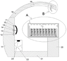
The invention will now be described in detail with reference to fig. 1-7, wherein for ease of description the orientations described below are now defined as follows: the up, down, left, right, and front-back directions described below correspond to the up, down, left, right, and front-back directions in the projection relationship of fig. 1 itself.
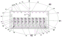
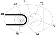
The internet-based teaching auxiliary equipment described with reference to fig. 1-7 includes an auxiliary box 24, an openable flap 76 is hinged to a front end surface of the auxiliary box 24, a storage chamber 46 is provided in the auxiliary box 24, a fixed box 35 is fixedly provided on an inner wall of a lower side of the storage chamber 46, a storage space 77 with an upward opening, a right opening and a front opening is provided in the fixed box 35, an identification mechanism 82 is provided on an inner lower side of the storage space 77, the identification mechanism 82 includes a transmission shaft 36 and a driving shaft 75 rotatably provided on an inner wall of a rear side of the storage space 77, the driving shaft 75 is provided on a right side of the transmission shaft 36, a transmission pulley 37 is fixedly provided on the transmission shaft 36, a gear 70 and a driving pulley 74 are fixedly provided on the driving shaft 75, the driving pulley 74 is provided on a front side of the gear 70, and the driving pulley 74 and the transmission pulley, a hemispherical block 38 is fixedly arranged on the belt 40, a motor 71 is fixedly arranged on the inner wall of the rear side of the placing space 77, the motor 71 is positioned on the right side of the gear 70, a motor shaft 73 is controlled on the front end surface of the motor 71, a sector gear 72 is fixedly arranged on the motor shaft 73, and the sector gear 72 can be meshed with the gear 70 in the rotating process;
the taking-out mechanism 80 is arranged on the inner upper side of the containing cavity 46, the taking-out mechanism 80 comprises a transverse slide rail 27 fixedly arranged on the inner wall of the upper side of the containing cavity 46, nine vertical slide rails 28 are fixedly arranged on the lower end face of the transverse slide rail 27, a knocking sensor 29 is fixedly arranged in each vertical slide rail 28, an electric slide block 32 is arranged in each transverse slide rail 27 in a sliding mode, and an electromagnet 31 is fixedly arranged on the lower end face of each electric slide block 32;
the upper side of the recognition mechanism 82 is provided with a storage block 41 fixedly arranged on the inner wall of the rear side of the placement space 77, nine storage mechanisms 81 are arranged in the storage block 41, each storage mechanism 81 corresponds to one vertical slide rail 28, each storage mechanism 81 comprises an oil cavity 45 arranged in the storage block 41, a sealing plate 44 is arranged in the oil cavity 45 in a sliding manner, a push rod 42 with the lower end positioned in the placement space 77 is fixedly arranged at the center of the lower end face of the sealing plate 44, bottom springs 43 with the lower ends fixedly connected with the inner wall of the lower side of the oil cavity 45 are fixedly arranged on the lower end face of the sealing plate 44 in a bilateral symmetry manner, a placement cavity 64 with an upward opening is arranged in the inner wall of the upper side of the oil cavity 45, a top cavity 57 with an upward opening is arranged on the inner wall of the upper side of the placement cavity 64, the sliding rod 52 with the upper end located in the top cavity 57 is slidably arranged in the oil pipe 51, the two sliding rods 52 are inserted into the inserting plate 55 through two slots 53 formed in the lower end face of the inserting plate 55, an iron block 54 is fixedly arranged on the rear end face of the inserting plate 55, a connecting block 56 is fixedly arranged on the right end face of the inserting plate 55, an identification block 86 is fixedly arranged on the upper end face of the connecting block 56, the right end face of the connecting block 56 is hinged to a placing plate 63 with the lower end located in the placing cavity 64, a first sliding groove 60 and a second sliding groove 68 are arranged in the placing plate 63, the second sliding groove 68 is located on the lower side of the first sliding groove 60, two connecting springs 58 are fixedly arranged on the inner wall on the left side of the first sliding groove 60 in a vertically symmetrical mode, two first sliding plates 59 are fixedly arranged at the right ends of the connecting springs 58, a rotating rod 61 is rotatably arranged on the right end face of the first, two pressure springs 65 are symmetrically and fixedly arranged on the inner wall of the left side of the second sliding groove 68, a second sliding plate 66 is fixedly arranged at the right end of each pressure spring 65, a fixing rod 67 is fixedly arranged on the right end face of each second sliding plate 66, and the right end of each fixing rod 67 is located in the mounting cavity 64 and fixedly provided with a clamping plate 69.
Beneficially, accomodate fixed control terminal 34 that is equipped with of chamber 46 left side inner wall, accomodate the fixed camera 33 that is equipped with of chamber 46 right side inner wall, accomodate chamber 46 upside inner wall and pass through shifting chute 26 and show groove 30 intercommunication external space, show groove 30 runs through shifting chute 26 front and back side inner wall, the fixed pen stand 25 that is equipped with of auxiliary box 24 up end, accomodate the fixed rotating electrical machines 78 that is equipped with of chamber 46 rear side inner wall, rotating electrical machines 78 control has rotation axis 79, the fixed rotary rod 85 that is equipped with on the rotation axis 79.
Advantageously, the oil chamber 45 on the upper side of the seal plate 44 and the oil pipe 51 on the lower side of the slide rod 52 are filled with hydraulic oil.
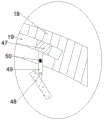
Beneficially, the auxiliary box 24 is fixedly arranged on the upper end face of the supporting column 20, the supporting column 20 is fixedly arranged on the right end face of the bottom plate 21, the seat 22 is fixedly arranged on the upper end face of the bottom plate 21, the pressure sensor 23 is embedded on the upper end face of the seat 22, the back plate 11 is fixedly arranged on the left end face of the bottom plate 21, the moving cavity 12 with an opening facing to the right is arranged in the back plate 11, the top motor 15 is fixedly arranged on the inner wall of the upper side of the moving cavity 12, the threaded shaft 13 is controlled by the lower end face of the top motor 15, the threaded shaft 13 is rotatably connected with the inner wall of the lower side of the moving cavity 12, the threaded shaft 13 is in threaded connection with the threaded block 14 which is slidably connected with the moving cavity 12, the right end face of the threaded block 14 is fixedly provided with the supporting rod 16 with the right end located in the external space, the, an arc-shaped groove 19 with a downward opening is formed in the arc-shaped plate 18, an arc-shaped electric sliding block 47 is arranged in the arc-shaped groove 19 in a sliding mode, a connecting rod 49 is fixedly arranged on the lower end face of the arc-shaped electric sliding block 47, a sound recognizer 50 is fixedly arranged on the connecting rod 49, and a player 48 is arranged at the lower end of the connecting rod 49 in a rotating mode.
In the initial state, the pressure spring 65 and the connection spring 58 are in the normal state.
The using method comprises the following steps:
before the first use, the turning plate 76 is manually opened, the clamping rod 62 and the clamping plate 69 are manually pulled rightwards, the textbook is clamped on the left sides of the clamping rod 62 and the clamping plate 69 through the stretched pressure spring 65 and the connecting spring 58, the textbook is in a state that the spine faces forwards and the cover faces rightwards, the textbook of each course is clamped on one group of the clamping rod 62 and the clamping plate 69, and the turning plate 76 is closed;
before internet teaching, a user sits on the seat 22 facing the right, the pressure sensor 23 is stressed, the camera 33 is automatically started, the top motor 15 is manually started, the threaded shaft 13 is controlled to rotate, the threaded shaft 13 drives the threaded block 14 to move up and down, so that the backrest 17 is provided with a vertical movement, the backrest 17 is adjusted to be attached to the back of the user, the top motor 15 is closed, the arc-shaped electric slide block 47 is started, the arc-shaped electric slide block 47 slides in the arc-shaped groove 19, the arc-shaped electric slide block 47 drives the player 48 to move, the user can observe the player 48 at a good watching angle, and textbooks and teacher information is recorded into the control terminal 34;
when internet teaching is carried out, the player 48 is started, the player 48 can play the teaching pictures and sounds of the course instructor, the sound recognizer 50 detects and analyzes the sound of the instructor and transmits data to the control terminal 34, the control terminal 34 controls the motor 71 to be started, the motor 71 drives the motor shaft 73 to rotate anticlockwise to drive the sector gear 72 to rotate anticlockwise, the sector gear 72 can be meshed with the gear 70 in the rotation process to drive the gear 70 to rotate, the driving belt wheel 74 rotates along with the gear 70 to drive the belt 40 to move, the hemispherical block 38 moves along with the belt 40, the push rods 42 are sequentially pushed to ascend in the movement process of the hemispherical block 38, the bottom spring 43 is compressed, when the hemispherical block 38 moves to the lower side of each push rod 42, the sector gear 72 is disengaged from the gear 70, so that the hemispherical block 38 stays at the lower side of the push rod 42 for a period of time, and the push rod, the hydraulic oil in the oil cavity 45 is pushed to be filled into the oil pipe 51, the sliding rod 52 is driven to ascend, the sliding rod 52 drives the plug-in board 55 to ascend, the placing board 63 ascends along with the plug-in board 55, the textbook of a course clamped on the placing board 63 is driven to ascend, at the moment, the camera 33 can identify the front cover of the ascending textbook and transmit data to the control terminal 34, the control terminal 34 analyzes whether the textbook corresponds to a course guide, and the camera 33 simultaneously identifies the information of the identification block 86 and gives the information to the control terminal 34;
if the text matching is not carried out, the next text matching is continued, if the text matching is carried out, the control terminal 34 controls the motor 71 to stop working, the control terminal 34 controls the stroke of the electric slide block 32 according to the information of the identification block 86, the control terminal 34 starts the electric slide block 32 to enable the electric slide block 32 to move along the transverse slide rail 27 to the vertical slide rail 28 corresponding to the matched text and enter the corresponding vertical slide rail 28 to move downwards until the electromagnet 31 is contacted with the corresponding iron block 54, the electric slide block 32 moves to impact the knocking sensor 29, the electromagnet 31 is controlled to be electrified to generate magnetic force, the electromagnet 31 attracts the iron block 54, the electric slide block 32 moves to the initial position along the transverse slide rail 27 after first rising to the transverse slide rail 27, the inserting plate 55 is driven to pull out the slide rod 52 first, then the inserting plate 55 is driven to move together with the placing plate 63 and the corresponding text on the placing plate 63, and after the electric slide block 32 stops moving, the rotating shaft 79 is driven to rotate, the rotating shaft 79 drives the rotating rod 85 to rotate, the rotating rod 85 pushes the placing plate 63 to rotate, the placing plate 63 is enabled to rotate right to the position of the display groove 30, the rotating shaft 79 is closed, a user can manually rotate the clamping rod 62 to use a textbook, and a pen can be taken out of the pen holder 25 to be used;
after the teaching is finished, the user manually rotates the clamping rod 62 to clamp the textbook, the textbook leaves the seat 22, the pressure sensor 23 detects pressure loss, a signal is sent to the control terminal 34, the control terminal 34 controls the rotating motor 78 to work, the rotating rod 85 rotates and resets, the placing plate 63 at the display groove 30 is changed into a vertical state under the action of self gravity, the control terminal 34 controls the electric slider 32 to move to the position corresponding to the vertical slide rail 28, the inserting plate 55 is driven to move, the slide rod 52 is inserted into the inserting plate 55 again, the placing plate 63 enters the placing cavity 64 again, when the electric slider 32 contacts the knocking sensor 29 again, the control terminal 34 controls the electromagnet 31 to be powered off, the electromagnet 31 does not suck the iron block 54 any more, the electric slider 32 moves and resets, and the initial state returns.
The above embodiments are merely illustrative of the technical ideas and features of the present invention, and the purpose thereof is to enable those skilled in the art to understand the contents of the present invention and implement the present invention, and not to limit the protection scope of the present invention. All equivalent changes and modifications made according to the spirit of the present invention should be covered within the protection scope of the present invention.