CN111744650A - A hydraulic crusher with a telescopic arm - Google Patents
A hydraulic crusher with a telescopic arm Download PDFInfo
- Publication number
- CN111744650A CN111744650A CN202010677383.1A CN202010677383A CN111744650A CN 111744650 A CN111744650 A CN 111744650A CN 202010677383 A CN202010677383 A CN 202010677383A CN 111744650 A CN111744650 A CN 111744650A
- Authority
- CN
- China
- Prior art keywords
- support arm
- telescopic
- arm
- frame
- fixed
- Prior art date
- Legal status (The legal status is an assumption and is not a legal conclusion. Google has not performed a legal analysis and makes no representation as to the accuracy of the status listed.)
- Pending
Links
- 238000000034 method Methods 0.000 description 5
- 238000010586 diagram Methods 0.000 description 3
- 230000009286 beneficial effect Effects 0.000 description 2
- 238000009434 installation Methods 0.000 description 2
- 238000012986 modification Methods 0.000 description 2
- 230000004048 modification Effects 0.000 description 2
- 238000003723 Smelting Methods 0.000 description 1
- 239000004566 building material Substances 0.000 description 1
- 230000000694 effects Effects 0.000 description 1
- 238000005516 engineering process Methods 0.000 description 1
- 238000005065 mining Methods 0.000 description 1
- 239000000126 substance Substances 0.000 description 1
- 238000006467 substitution reaction Methods 0.000 description 1
- XLYOFNOQVPJJNP-UHFFFAOYSA-N water Substances O XLYOFNOQVPJJNP-UHFFFAOYSA-N 0.000 description 1
Images


Classifications
-
- B—PERFORMING OPERATIONS; TRANSPORTING
- B02—CRUSHING, PULVERISING, OR DISINTEGRATING; PREPARATORY TREATMENT OF GRAIN FOR MILLING
- B02C—CRUSHING, PULVERISING, OR DISINTEGRATING IN GENERAL; MILLING GRAIN
- B02C23/00—Auxiliary methods or auxiliary devices or accessories specially adapted for crushing or disintegrating not provided for in preceding groups or not specially adapted to apparatus covered by a single preceding group
Landscapes
- Engineering & Computer Science (AREA)
- Food Science & Technology (AREA)
- Crushing And Grinding (AREA)
Abstract
Description
技术领域technical field
本发明涉及液压破碎设备技术领域,具体为一种具有伸缩臂的液压破碎机。The invention relates to the technical field of hydraulic crushing equipment, in particular to a hydraulic crusher with a telescopic arm.
背景技术Background technique
液压破碎机广泛运用于矿山、冶炼、建材、公路、铁路、水利和化学工业等众多部门,具有破碎比大、产品粒度均匀、结构简单、工作可靠、维修简便、运营费用经济等特点,目前,现有的液压破碎机中不具备伸缩臂的功能等不足,因此有必要对现有技术进行改进,以解决上述问题。Hydraulic crushers are widely used in mining, smelting, building materials, highways, railways, water conservancy and chemical industries and many other sectors. The existing hydraulic crusher does not have the function of telescopic arm and other shortcomings, so it is necessary to improve the existing technology to solve the above problems.
发明内容SUMMARY OF THE INVENTION
(一)解决的技术问题(1) Technical problems solved
本发明的目的在于提供一种具有伸缩臂的液压破碎机,以解决上述背景技术中提出的问题。The purpose of the present invention is to provide a hydraulic breaker with a telescopic arm to solve the problems raised in the above background art.
(二)技术方案(2) Technical solutions
为实现上述目的,本发明提供如下技术方案:一种具有伸缩臂的液压破碎机,包括底座,所述底座的上端固定有第一支臂,所述第一支臂的右上方设置有第二支臂,所述第二支臂的右下方设置有破碎架,所述第一支臂与第二支臂的上端均固定有安装架,所述第一支臂上的安装架上固定有第一液压缸,所述第二支臂上的安装架上固定有第二液压缸,所述第一支臂的前后端均设置有安装座,所述安装座的外侧均固定有伸缩箱,所述伸缩箱的内部均开设有伸缩孔,所述伸缩孔的内部均设置有伸缩杆,所述第二支臂的前后方相对应伸缩杆的位置处均设置有旋转架。In order to achieve the above purpose, the present invention provides the following technical solutions: a hydraulic breaker with a telescopic arm, comprising a base, a first arm is fixed on the upper end of the base, and a second arm is arranged on the upper right of the first arm. A support arm, a crushing frame is arranged at the lower right of the second support arm, a mounting frame is fixed on the upper ends of the first support arm and the second support arm, and a first support arm is fixed on the mounting frame on the first support arm. A hydraulic cylinder, a second hydraulic cylinder is fixed on the mounting frame on the second support arm, the front and rear ends of the first support arm are provided with mounting seats, and the outer sides of the mounting seats are fixed with telescopic boxes, so The telescopic box is provided with a telescopic hole inside, the telescopic hole is provided with a telescopic rod, and a rotating frame is provided at the front and rear of the second arm corresponding to the position of the telescopic rod.
优选的,所述第二支臂的末端的前后侧均设置有滑动架,所述滑动架与第二支臂活动连接。Preferably, the front and rear sides of the end of the second support arm are provided with a sliding frame, and the sliding frame is movably connected with the second support arm.
优选的,所述破碎架的右上方设置有活动板,所述活动板的下端与破碎架的上端活动连接,所述活动板的上端与滑动架的右端活动连接。Preferably, a movable plate is provided on the upper right of the crushing frame, the lower end of the movable plate is movably connected with the upper end of the crushing frame, and the upper end of the movable plate is movably connected with the right end of the sliding frame.
优选的,所述第一液压缸的活塞端与第二支臂固定连接,所述第二液压缸的活塞端与滑动架固定连接。Preferably, the piston end of the first hydraulic cylinder is fixedly connected to the second support arm, and the piston end of the second hydraulic cylinder is fixedly connected to the sliding frame.
优选的,所述伸缩杆分别与相对应的旋转架固定连接,所述安装座上开设有安装孔,所述安装孔内设置有螺栓,所述安装座通过螺栓安装在第一支臂上。Preferably, the telescopic rods are respectively fixedly connected with the corresponding rotating frames, the mounting seat is provided with a mounting hole, a bolt is arranged in the mounting hole, and the mounting seat is mounted on the first support arm through the bolt.
优选的,所述旋转架上相对应第二支臂的一端均固定有转动杆,所述转动杆上相对应第二支臂的一端均设置有轴承,所述转动杆通过轴承与第二支臂活动连接。Preferably, one end of the rotating frame corresponding to the second support arm is fixed with a rotating rod, and one end of the rotating rod corresponding to the second support arm is provided with a bearing, and the rotating rod is connected to the second support through the bearing. Arm articulation.
(三)有益效果(3) Beneficial effects
本发明提供了一种具有伸缩臂的液压破碎机,具备以下有益效果:The invention provides a hydraulic crusher with a telescopic arm, which has the following beneficial effects:
(1)本发明通过设置伸缩箱、伸缩杆和旋转架,当需要将第一支臂与第二支臂之间的距离调节时,当需要伸缩液压破碎机的第一支臂与第二支臂上,通过控制第一液压缸工作,第一液压缸的活塞端开始推动第二支臂向前移动,由于第二支臂与第一支臂的连接方式是通过伸缩箱与旋转架连接的,因此第二支臂的位置发生移动后,第一支臂与第二支臂之间的距离会变长,通过第二支臂的移动,带动旋转架的移动,由于旋转架与伸缩杆的端面固定在一起,因此旋转架会将伸缩杆在伸缩箱内的伸缩孔内向外拉动,解决了液压破碎机中不具备伸缩臂的功能的问题,同时具备结构简单,便于安装与拆卸的好处。(1) In the present invention, by setting the telescopic box, the telescopic rod and the rotating frame, when the distance between the first arm and the second arm needs to be adjusted, when the first arm and the second arm of the hydraulic crusher need to be telescopic On the arm, by controlling the work of the first hydraulic cylinder, the piston end of the first hydraulic cylinder starts to push the second arm to move forward, because the connection between the second arm and the first arm is through the telescopic box and the rotating frame. , so after the position of the second support arm moves, the distance between the first support arm and the second support arm will become longer, and the movement of the second support arm will drive the movement of the rotating frame. The end faces are fixed together, so the rotating frame will pull the telescopic rod outward in the telescopic hole in the telescopic box, which solves the problem that the hydraulic crusher does not have the function of the telescopic arm, and has the advantages of simple structure and easy installation and disassembly.
附图说明Description of drawings
图1为本发明图的结构图;Fig. 1 is the structure diagram of the figure of the present invention;
图2为本发明图1中的伸缩箱的内部结构图;Fig. 2 is the internal structure diagram of the telescopic box in Fig. 1 of the present invention;
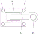
图3为本发明图1的旋转架的结构图。FIG. 3 is a structural diagram of the rotating frame of FIG. 1 of the present invention.
图中附图标记为:1、第一液压缸;2、第二支臂;3、安装架;4、第二液压缸;5、滑动架;6、破碎架;7、底座;8、第一支臂;9、伸缩箱;10、螺栓;11、安装孔;12、安装座;13、旋转架;14、伸缩杆;15、伸缩孔;16、转动杆;17、轴承;18、活动板。The reference signs in the figure are: 1, the first hydraulic cylinder; 2, the second arm; 3, the mounting frame; 4, the second hydraulic cylinder; 5, the sliding frame; 6, the crushing frame; 7, the base; 8, the first One arm; 9, telescopic box; 10, bolt; 11, mounting hole; 12, mounting seat; 13, rotating frame; 14, telescopic rod; 15, telescopic hole; 16, rotating rod; 17, bearing; 18, activity plate.
具体实施方式Detailed ways
下面将结合本发明实施例中的附图,对本发明实施例中的技术方案进行清楚、完整地描述,显然,所描述的实施例仅仅是本发明一部分实施例,而不是全部的实施例。基于本发明中的实施例,本领域普通技术人员在没有做出创造性劳动前提下所获得的所有其他实施例,都属于本发明保护的范围。The technical solutions in the embodiments of the present invention will be clearly and completely described below with reference to the accompanying drawings in the embodiments of the present invention. Obviously, the described embodiments are only a part of the embodiments of the present invention, but not all of the embodiments. Based on the embodiments of the present invention, all other embodiments obtained by those of ordinary skill in the art without creative efforts shall fall within the protection scope of the present invention.
如图1-3所示,本发明提供一种技术方案:一种具有伸缩臂的液压破碎机,包括底座7,底座7的上端固定有第一支臂8,第一支臂8的右上方设置有第二支臂2,第二支臂2的右下方设置有破碎架6,第一支臂8与第二支臂2的上端均固定有安装架3,第一支臂8上的安装架3上固定有第一液压缸1,第二支臂2上的安装架3上固定有第二液压缸4,第一支臂8的前后端均设置有安装座12,安装座12的外侧均固定有伸缩箱9,伸缩箱9的内部均开设有伸缩孔15,伸缩孔15的内部均设置有伸缩杆14,第二支臂2的前后方相对应伸缩杆14的位置处均设置有旋转架13。As shown in Figures 1-3, the present invention provides a technical solution: a hydraulic crusher with a telescopic arm, comprising a
第二支臂2的末端的前后侧均设置有滑动架5,通过滑动架5,使得破碎架6的固定更加的稳定,滑动架5与第二支臂2活动连接。The front and rear sides of the end of the
破碎架6的右上方设置有活动板18,活动板18在滑动架5上旋转,能够使的破碎架6的活动更加的灵活,活动板18的下端与破碎架6的上端活动连接,活动板18的上端与滑动架5的右端活动连接。The upper right of the crushing
第一液压缸1的活塞端与第二支臂2固定连接,通过第一液压缸1的工作,使得将第一支臂8与第二支臂2的距离加长,第二液压缸4的活塞端与滑动架5固定连接。The piston end of the first
伸缩杆14分别与相对应的旋转架13固定连接,安装座12上开设有安装孔11,安装孔11内设置有螺栓10,当需要将安装座12从第一支臂8上拆卸下时,直接将安装座12上的螺栓10拧出,即可将安装座12拆卸,安装座12通过螺栓10安装在第一支臂8上。The
旋转架13上相对应第二支臂2的一端均固定有转动杆16,旋转架13直接套在转动杆16上,因此,旋转架13能够直接从转动杆16上取出,转动杆16上相对应第二支臂2的一端均设置有轴承17,通过转动杆16上的轴承17,当第二支臂2在移动时,会拉动伸缩杆14在伸缩箱9内移动,进而使得第二支臂2在转动杆16上转动,因此轴承17避免第二支臂2与转动杆16之间摩擦,转动杆16通过轴承17与第二支臂2活动连接。One end of the rotating
工作原理:本发明在使用时,当需要伸缩液压破碎机的第一支臂8与第二支臂2上,通过控制第一液压缸1工作,第一液压缸1的活塞端开始推动第二支臂2向前移动,由于第二支臂2与第一支臂8的连接方式是通过伸缩箱9与旋转架13连接的,因此第二支臂2的位置发生移动后,第一支臂8与第二支臂2之间的距离会变长,通过第二支臂2的移动,带动旋转架13的移动,由于旋转架13与伸缩杆14的端面固定在一起,因此旋转架13会将伸缩杆14在伸缩箱9内的伸缩孔15内向外拉动,通过转动杆16与第二支臂2之间的轴承17,导致第二支臂2能够在转动杆16上旋转,当需要将伸缩箱9拆卸下来时,将安装座12上的螺栓10拧出,再将旋转架13从转动杆16上取出,即可将伸缩箱9上安装座12在第一支臂8上拆卸下。Working principle: When the present invention is in use, when the
需要说明的是,在本文中,诸如第一和第二等之类的关系术语仅仅用来将一个实体或者操作与另一个实体或操作区分开来,而不一定要求或者暗示这些实体或操作之间存在任何这种实际的关系或者顺序。而且,术语“包括”、“包含”或者其任何其他变体意在涵盖非排他性的包含,从而使得包括一系列要素的过程、方法、物品或者设备不仅包括那些要素,而且还包括没有明确列出的其他要素,或者是还包括为这种过程、方法、物品或者设备所固有的要素。It should be noted that, in this document, relational terms such as first and second are only used to distinguish one entity or operation from another entity or operation, and do not necessarily require or imply any relationship between these entities or operations. any such actual relationship or sequence exists. Moreover, the terms "comprising", "comprising" or any other variation thereof are intended to encompass a non-exclusive inclusion such that a process, method, article or device that includes a list of elements includes not only those elements, but also includes not explicitly listed or other elements inherent to such a process, method, article or apparatus.
尽管已经示出和描述了本发明的实施例,对于本领域的普通技术人员而言,可以理解在不脱离本发明的原理和精神的情况下可以对这些实施例进行多种变化、修改、替换和变型,本发明的范围由所附权利要求及其等同物限定。Although embodiments of the present invention have been shown and described, it will be understood by those skilled in the art that various changes, modifications, and substitutions can be made in these embodiments without departing from the principle and spirit of the invention and modifications, the scope of the present invention is defined by the appended claims and their equivalents.
Claims (6)
Priority Applications (1)
| Application Number | Priority Date | Filing Date | Title |
|---|---|---|---|
| CN202010677383.1A CN111744650A (en) | 2020-07-15 | 2020-07-15 | A hydraulic crusher with a telescopic arm |
Applications Claiming Priority (1)
| Application Number | Priority Date | Filing Date | Title |
|---|---|---|---|
| CN202010677383.1A CN111744650A (en) | 2020-07-15 | 2020-07-15 | A hydraulic crusher with a telescopic arm |
Publications (1)
| Publication Number | Publication Date |
|---|---|
| CN111744650A true CN111744650A (en) | 2020-10-09 |
Family
ID=72710489
Family Applications (1)
| Application Number | Title | Priority Date | Filing Date |
|---|---|---|---|
| CN202010677383.1A Pending CN111744650A (en) | 2020-07-15 | 2020-07-15 | A hydraulic crusher with a telescopic arm |
Country Status (1)
| Country | Link |
|---|---|
| CN (1) | CN111744650A (en) |
Cited By (1)
| Publication number | Priority date | Publication date | Assignee | Title |
|---|---|---|---|---|
| CN119819441A (en) * | 2025-01-24 | 2025-04-15 | 北京科技大学 | Multi-angle crushing device for bridge highway subgrade performance test |
Citations (7)
| Publication number | Priority date | Publication date | Assignee | Title |
|---|---|---|---|---|
| JPS6458487A (en) * | 1987-08-26 | 1989-03-06 | Shikoku Elec Power | Power transmission mechanism of robot arm |
| CN202078919U (en) * | 2011-05-05 | 2011-12-21 | 焦作煤业(集团)新乡能源有限公司 | Lump coal crushing device for fully mechanized coal mining face |
| CN202611693U (en) * | 2012-06-21 | 2012-12-19 | 中铁隧道装备制造有限公司 | Combined type cantilever heading machine |
| CN208695098U (en) * | 2018-08-03 | 2019-04-05 | 北京新能雅特科技发展有限公司 | A kind of hydraulic breaker |
| CN209466265U (en) * | 2019-02-10 | 2019-10-08 | 青岛科技大学 | Telescopic hydraulic mechanical arm suitable for shield machine tool changing robot |
| CN210585083U (en) * | 2019-07-22 | 2020-05-22 | 中煤张家口煤矿机械有限责任公司 | Large block coal gas dynamic crushing device in working face conveying and unloading area |
| CN212284390U (en) * | 2020-07-15 | 2021-01-05 | 马鞍山盛禾新智能科技有限公司 | Hydraulic crusher with telescopic arm |
-
2020
- 2020-07-15 CN CN202010677383.1A patent/CN111744650A/en active Pending
Patent Citations (7)
| Publication number | Priority date | Publication date | Assignee | Title |
|---|---|---|---|---|
| JPS6458487A (en) * | 1987-08-26 | 1989-03-06 | Shikoku Elec Power | Power transmission mechanism of robot arm |
| CN202078919U (en) * | 2011-05-05 | 2011-12-21 | 焦作煤业(集团)新乡能源有限公司 | Lump coal crushing device for fully mechanized coal mining face |
| CN202611693U (en) * | 2012-06-21 | 2012-12-19 | 中铁隧道装备制造有限公司 | Combined type cantilever heading machine |
| CN208695098U (en) * | 2018-08-03 | 2019-04-05 | 北京新能雅特科技发展有限公司 | A kind of hydraulic breaker |
| CN209466265U (en) * | 2019-02-10 | 2019-10-08 | 青岛科技大学 | Telescopic hydraulic mechanical arm suitable for shield machine tool changing robot |
| CN210585083U (en) * | 2019-07-22 | 2020-05-22 | 中煤张家口煤矿机械有限责任公司 | Large block coal gas dynamic crushing device in working face conveying and unloading area |
| CN212284390U (en) * | 2020-07-15 | 2021-01-05 | 马鞍山盛禾新智能科技有限公司 | Hydraulic crusher with telescopic arm |
Cited By (1)
| Publication number | Priority date | Publication date | Assignee | Title |
|---|---|---|---|---|
| CN119819441A (en) * | 2025-01-24 | 2025-04-15 | 北京科技大学 | Multi-angle crushing device for bridge highway subgrade performance test |
Similar Documents
| Publication | Publication Date | Title |
|---|---|---|
| CN114837712B (en) | Anchor drilling and grouting integrated trolley for tunnel | |
| CN204093493U (en) | A kind of adjustment of wedge formula jaw crusher | |
| CN207998322U (en) | A kind of stable native storage bin hopper device for discharging | |
| CN212284390U (en) | Hydraulic crusher with telescopic arm | |
| CN211420901U (en) | Hang basket side form subassembly convenient to drawing of patterns | |
| CN218879274U (en) | Cantilever crane hoist stand reinforcing mechanism | |
| CN210296600U (en) | Novel communication engineering antenna support convenient to adjust device | |
| CN108625294B (en) | One kind builds a bridge efficient construction equipment | |
| CN214662000U (en) | Sealing device on pull rod of roller disc type medium-speed coal mill | |
| CN211976375U (en) | Combined type TBM bearing structure | |
| CN116356846A (en) | A support-removed and strengthened structure in a deep foundation pit | |
| CN212929008U (en) | Water conservancy pipeline strutting arrangement | |
| CN207716868U (en) | A kind of furnace ramming machine that intelligence degree is high | |
| CN209758898U (en) | A tower crane with adjustable lifting contact area | |
| CN211341368U (en) | A roof frame steel support structure | |
| CN107715953A (en) | A kind of building foundation engineering disposed waste recycling equipment | |
| CN222234241U (en) | A convenient mobile high and low voltage reactive power compensation room | |
| CN216109140U (en) | Solar wallboard for building outer wall | |
| CN222769431U (en) | Material handling device for water conservancy project construction | |
| CN222046887U (en) | A pipe support structure for water conservancy construction | |
| CN214615461U (en) | A formwork card for building construction | |
| CN217434624U (en) | Integral lifting mechanism for cloth bottom plate of brick making production line | |
| CN223674257U (en) | Double-arm support of aerial working equipment | |
| CN222453324U (en) | Garbage compression transfer equipment with hopper lifting mechanism | |
| CN219548795U (en) | Mobile rock crushing device for tunnel construction |
Legal Events
| Date | Code | Title | Description |
|---|---|---|---|
| PB01 | Publication | ||
| PB01 | Publication | ||
| SE01 | Entry into force of request for substantive examination | ||
| SE01 | Entry into force of request for substantive examination | ||
| WD01 | Invention patent application deemed withdrawn after publication |
Application publication date: 20201009 |
|
| WD01 | Invention patent application deemed withdrawn after publication |