CN111731953A - A cable storage and take-up and release device - Google Patents
A cable storage and take-up and release device Download PDFInfo
- Publication number
- CN111731953A CN111731953A CN202010686879.5A CN202010686879A CN111731953A CN 111731953 A CN111731953 A CN 111731953A CN 202010686879 A CN202010686879 A CN 202010686879A CN 111731953 A CN111731953 A CN 111731953A
- Authority
- CN
- China
- Prior art keywords
- cable
- roller
- main body
- winding
- drives
- Prior art date
- Legal status (The legal status is an assumption and is not a legal conclusion. Google has not performed a legal analysis and makes no representation as to the accuracy of the status listed.)
- Pending
Links
- 238000004804 winding Methods 0.000 claims abstract description 37
- 238000003780 insertion Methods 0.000 claims description 4
- 230000037431 insertion Effects 0.000 claims description 4
- 238000005096 rolling process Methods 0.000 claims description 3
- 238000000034 method Methods 0.000 description 4
- 239000002689 soil Substances 0.000 description 3
- 238000010586 diagram Methods 0.000 description 2
- 238000009412 basement excavation Methods 0.000 description 1
- 238000010276 construction Methods 0.000 description 1
- 230000000694 effects Effects 0.000 description 1
- 238000001125 extrusion Methods 0.000 description 1
- 230000008092 positive effect Effects 0.000 description 1
Images



Classifications
-
- B—PERFORMING OPERATIONS; TRANSPORTING
- B65—CONVEYING; PACKING; STORING; HANDLING THIN OR FILAMENTARY MATERIAL
- B65H—HANDLING THIN OR FILAMENTARY MATERIAL, e.g. SHEETS, WEBS, CABLES
- B65H75/00—Storing webs, tapes, or filamentary material, e.g. on reels
- B65H75/02—Cores, formers, supports, or holders for coiled, wound, or folded material, e.g. reels, spindles, bobbins, cop tubes, cans, mandrels or chucks
- B65H75/34—Cores, formers, supports, or holders for coiled, wound, or folded material, e.g. reels, spindles, bobbins, cop tubes, cans, mandrels or chucks specially adapted or mounted for storing and repeatedly paying-out and re-storing lengths of material provided for particular purposes, e.g. anchored hoses, power cables
- B65H75/38—Cores, formers, supports, or holders for coiled, wound, or folded material, e.g. reels, spindles, bobbins, cop tubes, cans, mandrels or chucks specially adapted or mounted for storing and repeatedly paying-out and re-storing lengths of material provided for particular purposes, e.g. anchored hoses, power cables involving the use of a core or former internal to, and supporting, a stored package of material
- B65H75/40—Cores, formers, supports, or holders for coiled, wound, or folded material, e.g. reels, spindles, bobbins, cop tubes, cans, mandrels or chucks specially adapted or mounted for storing and repeatedly paying-out and re-storing lengths of material provided for particular purposes, e.g. anchored hoses, power cables involving the use of a core or former internal to, and supporting, a stored package of material mobile or transportable
-
- B—PERFORMING OPERATIONS; TRANSPORTING
- B65—CONVEYING; PACKING; STORING; HANDLING THIN OR FILAMENTARY MATERIAL
- B65H—HANDLING THIN OR FILAMENTARY MATERIAL, e.g. SHEETS, WEBS, CABLES
- B65H75/00—Storing webs, tapes, or filamentary material, e.g. on reels
- B65H75/02—Cores, formers, supports, or holders for coiled, wound, or folded material, e.g. reels, spindles, bobbins, cop tubes, cans, mandrels or chucks
- B65H75/34—Cores, formers, supports, or holders for coiled, wound, or folded material, e.g. reels, spindles, bobbins, cop tubes, cans, mandrels or chucks specially adapted or mounted for storing and repeatedly paying-out and re-storing lengths of material provided for particular purposes, e.g. anchored hoses, power cables
- B65H75/38—Cores, formers, supports, or holders for coiled, wound, or folded material, e.g. reels, spindles, bobbins, cop tubes, cans, mandrels or chucks specially adapted or mounted for storing and repeatedly paying-out and re-storing lengths of material provided for particular purposes, e.g. anchored hoses, power cables involving the use of a core or former internal to, and supporting, a stored package of material
- B65H75/44—Constructional details
- B65H75/4481—Arrangements or adaptations for driving the reel or the material
-
- B—PERFORMING OPERATIONS; TRANSPORTING
- B65—CONVEYING; PACKING; STORING; HANDLING THIN OR FILAMENTARY MATERIAL
- B65H—HANDLING THIN OR FILAMENTARY MATERIAL, e.g. SHEETS, WEBS, CABLES
- B65H75/00—Storing webs, tapes, or filamentary material, e.g. on reels
- B65H75/02—Cores, formers, supports, or holders for coiled, wound, or folded material, e.g. reels, spindles, bobbins, cop tubes, cans, mandrels or chucks
- B65H75/34—Cores, formers, supports, or holders for coiled, wound, or folded material, e.g. reels, spindles, bobbins, cop tubes, cans, mandrels or chucks specially adapted or mounted for storing and repeatedly paying-out and re-storing lengths of material provided for particular purposes, e.g. anchored hoses, power cables
- B65H75/38—Cores, formers, supports, or holders for coiled, wound, or folded material, e.g. reels, spindles, bobbins, cop tubes, cans, mandrels or chucks specially adapted or mounted for storing and repeatedly paying-out and re-storing lengths of material provided for particular purposes, e.g. anchored hoses, power cables involving the use of a core or former internal to, and supporting, a stored package of material
- B65H75/44—Constructional details
- B65H75/48—Automatic re-storing devices
-
- B—PERFORMING OPERATIONS; TRANSPORTING
- B65—CONVEYING; PACKING; STORING; HANDLING THIN OR FILAMENTARY MATERIAL
- B65H—HANDLING THIN OR FILAMENTARY MATERIAL, e.g. SHEETS, WEBS, CABLES
- B65H2701/00—Handled material; Storage means
- B65H2701/30—Handled filamentary material
- B65H2701/34—Handled filamentary material electric cords or electric power cables
Landscapes
- Storing, Repeated Paying-Out, And Re-Storing Of Elongated Articles (AREA)
Abstract
Description
技术领域technical field
本发明属于电缆收放技术领域,尤其涉及一种电缆储存及收放线装置。The invention belongs to the technical field of cable retraction and release, and in particular relates to a cable storage and retraction and release device.
背景技术Background technique
盾构机械指的是一种盾构机,该盾构机可对泥土等地进行挖掘,是隧道掘进的主要专用工程机械,而此机械需要使用到电缆,通过电缆对电流进行传导,便于机械能够运作,而该电缆普遍需要放置在一个电缆储存装置中,进行储存保护,与便防止其受损。Shield machine refers to a shield machine, which can excavate soil and other places. It is the main special construction machine for tunnel excavation. This machine needs to use cables to conduct current through cables, which is convenient for machinery. To be able to operate, the cable generally needs to be placed in a cable storage device for storage protection and to prevent damage.
现有的储存装置具有一些缺点,在盾构机械在运作时,需要将电缆从储存装置中取出,但是该过程较为麻烦,不能够直接进行放线还容易打结。The existing storage device has some disadvantages. When the shield machine is in operation, the cable needs to be taken out from the storage device, but the process is cumbersome, and the cable cannot be directly paid off and is easily knotted.
发明内容SUMMARY OF THE INVENTION
为解决上述问题,本发明的目的是提供一种电缆储存及收放线装置,该装置收放线方便。In order to solve the above-mentioned problems, the purpose of the present invention is to provide a cable storage, retraction and payout device, which is convenient for retraction and payout.
为实现上述目的,本发明的技术方案为:For achieving the above object, the technical scheme of the present invention is:
一种电缆储存及收放线装置,包括:A cable storage and retraction device, comprising:
主体;main body;
收卷组件,转动连接于所述主体,电缆缠绕于所述收卷组件,且所述收卷组件设有盘簧,所述盘簧一端连接所述收卷组件、另一端连接所述主体;a winding assembly, rotatably connected to the main body, the cable is wound around the winding assembly, and the winding assembly is provided with a coil spring, one end of the coil spring is connected to the winding assembly, and the other end is connected to the main body;
驱动组件,驱动所述电缆移动;a drive assembly to drive the cable to move;
其中,放线时所述驱动组件带动所述电缆移动,所述电缆带动所述收卷组件转动,所述收卷组件带动所述盘簧蓄力;收线时所述驱动组件带动所述电缆反向移动,所述盘簧带动所述收卷组件转动以收线。Wherein, the drive assembly drives the cable to move when the wire is paid off, the cable drives the take-up assembly to rotate, and the take-up assembly drives the coil spring to store force; when the wire is taken up, the drive assembly drives the cable Reverse movement, the coil spring drives the winding assembly to rotate to take up the wire.
根据本发明一实施例,所述驱动组件包括第一驱动单元以及转动连接于所述主体的第一滚筒和第二滚筒,所述电缆的输出端设于所述第一滚筒和第二滚筒之间,所述第一驱动单元驱动所述第一滚筒和所述第二滚筒滚动,所述第一滚筒和所述第二滚筒滚动时带动所述电缆移动。According to an embodiment of the present invention, the driving assembly includes a first driving unit, a first drum and a second drum rotatably connected to the main body, and an output end of the cable is provided between the first drum and the second drum During the time, the first driving unit drives the first roller and the second roller to roll, and the first roller and the second roller drive the cable to move when the first roller and the second roller are rolling.
根据本发明一实施例,所述第一驱动单元包括第一手轮和相互啮合的第一齿轮、第二齿轮,所述第一齿轮的一端面连接于所述第一滚筒,所述第二齿轮的一端面连接于所述第二滚筒,所述第一手轮通过第一转动杆连接于所述第一齿轮的另一端面。According to an embodiment of the present invention, the first driving unit includes a first hand wheel, a first gear and a second gear that mesh with each other, one end surface of the first gear is connected to the first drum, and the second One end surface of the gear is connected to the second drum, and the first hand wheel is connected to the other end surface of the first gear through a first rotating rod.
根据本发明一实施例,包括固定组件和第二驱动单元,所述固定组件滑动连接于所述主体,所述第二驱动单元驱动所述固定组件上下滑动,所述固定组件底部设有插入部,所述插入部用于插入地面以固定所述主体。According to an embodiment of the present invention, it includes a fixing component and a second driving unit, the fixing component is slidably connected to the main body, the second driving unit drives the fixing component to slide up and down, and an insertion portion is provided at the bottom of the fixing component , the insertion part is used for inserting into the ground to fix the main body.
根据本发明一实施例,所述第二驱动单元包括:According to an embodiment of the present invention, the second driving unit includes:
螺杆,所述螺杆一端连接于所述固定组件;a screw, one end of the screw is connected to the fixing component;
第二手轮,连接于第二转动杆,所述第二转接杆转动连接于所述主体;a second hand wheel, connected to a second rotating rod, and the second adapter rod is rotatably connected to the main body;
第一锥齿轮,连接于所述第二转动杆;a first bevel gear, connected to the second rotating rod;
第二锥齿轮,套设且螺纹连接于所述螺杆,且与所述第一锥齿轮啮合;a second bevel gear, sleeved and threadedly connected to the screw rod, and meshed with the first bevel gear;
转动所述第二手轮带动所述第一锥齿轮和第二锥齿轮转动,所述第二锥齿轮带动所述螺杆上下移动以带动所述固定组件上下滑动。Rotating the second hand wheel drives the first bevel gear and the second bevel gear to rotate, and the second bevel gear drives the screw to move up and down to drive the fixed assembly to slide up and down.
根据本发明一实施例,所述收卷组件包括:According to an embodiment of the present invention, the winding assembly includes:
收卷筒,转动连接于所述主体,所述电缆缠绕于所述收卷筒;a reel, which is rotatably connected to the main body, and the cable is wound around the reel;
两个限位盘,套设于所述收卷筒;two limit discs are sleeved on the reel;
连接件,一端连接于所述收卷筒、另一端连接于所述盘簧。The connecting piece has one end connected to the winding drum and the other end connected to the coil spring.
根据本发明一实施例,所述主体底部设有万向自锁轮。According to an embodiment of the present invention, the bottom of the main body is provided with a universal self-locking wheel.
本发明由于采用以上技术方案,使其与现有技术相比具有以下的优点和积极效果:Compared with the prior art, the present invention has the following advantages and positive effects due to the adoption of the above technical solutions:
(1)本发明实施例中设置主体、收卷组件、驱动组件,放线时通过驱动组件驱动电缆线移动以放线;收线时通过驱动组件反向移动电缆,再配合盘簧实现收线。实现了电缆的收纳以及电缆的收放线,且收放线十分方便。(1) In the embodiment of the present invention, a main body, a winding assembly, and a driving assembly are provided. When paying off, the cable is driven to move by the driving assembly to pay off the wire; when taking up, the cable is moved in the opposite direction by the driving assembly, and then the coil spring is used to realize the take-up. . The cable storage and the cable retraction and release line are realized, and the retraction and release line is very convenient.
(2)本发明实施例中驱动组件包括第一滚筒、第二滚筒和第一驱动单元,通过第一滚筒和第二滚筒对电缆的滚动挤压产生摩擦力,实现带动电缆移动,十分简单方便。(2) In the embodiment of the present invention, the drive assembly includes a first roller, a second roller and a first drive unit, and the friction force is generated by the rolling extrusion of the cable by the first roller and the second roller, so as to drive the cable to move, which is very simple and convenient .
(3)本发明实施例中设有固定组件,实现了插入地面以固定主体,使本装置使用时不会侧翻,更加安全。(3) The embodiment of the present invention is provided with a fixing component, which can be inserted into the ground to fix the main body, so that the device will not roll over when in use, and is more secure.
附图说明Description of drawings
下面结合附图对本发明的具体实施方式作进一步详细说明,其中:The specific embodiments of the present invention will be described in further detail below in conjunction with the accompanying drawings, wherein:
图1为本发明的一种电缆储存及收放线装置整体示意图;FIG. 1 is an overall schematic diagram of a cable storage and take-up and pay-out device according to the present invention;
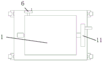
图2为本发明的一种电缆储存及收放线装置侧视图;Figure 2 is a side view of a cable storage and take-up and pay-off device of the present invention;
图3为本发明的一种电缆储存及收放线装置俯视图;3 is a top view of a cable storage and take-up and pay-out device according to the present invention;
图4为本发明的一种电缆储存及收放线装置收卷组件示意图。FIG. 4 is a schematic diagram of a reeling assembly of a cable storage and reeling and reeling device according to the present invention.
附图标记说明:Description of reference numbers:
1:主体;2:盘簧;3:第一滚筒;4:第二滚筒;5:电缆;6:第一手轮;7:第一齿轮;8:第二齿轮;9:第一转动杆;10:螺杆;11:第二手轮;12:第一锥齿轮;13:第二锥齿轮;14:第二转动杆;15:收卷筒;16:限位盘;17:连接件;18:万向自锁轮;19:锥块;20:固定杆。1: Main body; 2: Coil spring; 3: First roller; 4: Second roller; 5: Cable; 6: First handwheel; 7: First gear; 8: Second gear; 9: First rotation lever ;10: Screw; 11: Second hand wheel; 12: First bevel gear; 13: Second bevel gear; 14: Second rotating rod; 15: Rewinding drum; 16: Limiting plate; 18: Universal self-locking wheel; 19: Cone block; 20: Fixed rod.
具体实施方式Detailed ways
以下结合附图和具体实施例对本发明作进一步详细说明。根据下面说明和权利要求书,本发明的优点和特征将更清楚。需说明的是,附图均采用非常简化的形式且均使用非精准的比率,仅用以方便、明晰地辅助说明本发明实施例的目的。The present invention will be further described in detail below with reference to the accompanying drawings and specific embodiments. The advantages and features of the present invention will become apparent from the following description and claims. It should be noted that, the accompanying drawings are all in a very simplified form and use imprecise ratios, and are only used to facilitate and clearly assist the purpose of explaining the embodiments of the present invention.
参看图1至4,本发明的核心是提供一种电缆储存及收放线装置,包括主体1、收卷组件、驱动组件,放线时通过驱动组件驱动电缆5移动以放线;收线时通过驱动组件反向移动电缆5,再配合盘簧2实现收线。实现了电缆5的收纳以及电缆5的收放线,且收放线十分方便。Referring to Figures 1 to 4, the core of the present invention is to provide a cable storage and take-up and pay-off device, including a
主体1为一承载结构,其底部设有万向自锁轮18,以方便移动。The
收卷组件设于主体1上,具体的,收卷组件包括收卷筒15、两个限位盘16和连接件17。收卷筒15转动连接于主体1,电缆5缠绕于收卷筒15;两个限位盘16套设于收卷筒15,用于对电缆5限位,使电缆5始终在两个限位盘16中间。连接件17一端固定连接于收卷筒15、另一端固定连接于盘簧2,盘簧2的另一端连接主体1。The winding assembly is arranged on the
驱动组件包括第一驱动单元、第一滚筒3和第二滚筒4,第一滚筒3和第二滚筒4均转动连接于主体1,电缆5从其一端穿设于第一滚筒3和第二滚筒4之间,且第一滚筒3和第二滚筒4挤压电缆5,第一驱动单元驱动第一滚筒3和第二滚筒4滚动,第一滚筒3和第二滚筒4滚动时与电缆5产生摩擦力,实现带动电缆5移动,十分简单方便。The drive assembly includes a first drive unit, a
第一驱动单元包括第一手轮6和相互啮合的第一齿轮7、第二齿轮8,第一齿轮7的一端面连接于第一滚筒3,第二齿轮8的一端面连接于第二滚筒4,第一手轮6通过第一转动杆9连接于第一齿轮7的另一端面,且第一转动杆9也转动连接于主体1,第一手轮6转动带动第一齿轮7和第二齿轮8转动,第一齿轮7和第二齿轮8分别带动第一滚筒3和第二滚筒4转动。The first drive unit includes a
当需要对电缆5放线时,转动第一手轮6,使第一滚筒3和第二滚筒4带动电缆5移动,电缆5移动带动收卷筒15转动,收卷筒15转动带动盘簧2蓄力,储存弹性力。When it is necessary to pay off the
当需要对电缆5收线时,反向转动第一手轮6,使第一滚筒3和第二滚筒4带动电缆5反向移动,同时盘簧2释放弹性力带动收卷筒15转动以收线。也就是说通过第一滚筒3、第二滚筒4和盘簧2的配合实现收线,因为通常电缆5很重,只通过盘簧2难以带动电缆5,因此先通过第一滚筒3和第二滚筒4拉动电缆5。When it is necessary to take up the
进一步的,还包括固定组件和第二驱动单元,固定组件滑动连接于主体1,第二驱动单元驱动固定组件上下滑动,固定组件底部设有插入部,插入部用于插入地面以固定主体1。盾构机械普遍用于开挖隧道等地,在过程中容易产生力对电缆5拉扯,而泥土较为疏松,容易产生侧倒发生危险等,因此设置固定组件,防止其倾倒。Further, it also includes a fixing component and a second driving unit. The fixing component is slidably connected to the
具体的,固定组件包括两个锥块19,锥块19下端呈锥形以形成插入部,锥块19滑动连接于主体1的下部,两个锥块19的上端通过固定杆20相互连接,第二驱动单元连接于固定杆20。Specifically, the fixing assembly includes two cone blocks 19, the lower ends of the cone blocks 19 are tapered to form the insertion portion, the cone blocks 19 are slidably connected to the lower part of the
第二驱动单元包括螺杆10、第二手轮11、第二转动杆14、第一锥齿轮12、第二锥齿轮13,螺杆10竖直设置且其一端固定连接于固定杆20,第二转接杆水平设置且转动连接于主体1,第二手轮11连接于第二转动杆14的一端,第一锥齿轮12连接于第二转动杆14的另一端。第二锥齿轮13中间设有螺纹孔,通过该螺纹孔套设且螺纹连接于螺杆10,第一锥齿轮12和第二锥齿轮13相互啮合。The second driving unit includes a
转动第二手轮11带动第一锥齿轮12和第二锥齿轮13转动,第二锥齿轮13转动带螺杆10上下移动,以带动固定杆20和两个锥块19上下移动,使锥块19的尖端插入地面实现固定,有效的防止主体1受到磕碰产生倾倒等问题。Rotating the
下面对本发明工作过程作进一步说明:The working process of the present invention is further described below:
首先通过万向自锁轮18将本装移动到需要工作的地方,然后用手旋转主体1上的第二手轮11,第二手轮11带动第一锥齿轮12和第二锥齿轮13转动,第二锥齿轮13转动使得螺杆10向下移动,螺杆10带动固定杆20和锥块19向下滑动,锥块19向下刺入到泥土的内部,达到固定的效果。First, move the device to the place where it needs to work through the universal self-locking
固定好后,旋转第一手轮6,第一手轮6带动第一齿轮7和第二齿轮8转动,第一齿轮7和第二齿轮8分别带动第一滚筒3和第二滚筒4转动,第一滚筒3和第二滚筒4对电缆5滚动挤压产生摩擦力,以使电缆5移动,实现放线,此时电缆5移动带动收卷筒15转动,收卷筒15转动带动盘簧2蓄力,储存弹性力。After fixing, rotate the
反向旋转第一手轮6,使第一滚筒3和第二滚筒4带动电缆5反向移动,同时盘簧2释放弹性力带动收卷筒15转动以收线。Rotate the
上面结合附图对本发明的实施方式作了详细说明,但是本发明并不限于上述实施方式。即使对本发明作出各种变化,倘若这些变化属于本发明权利要求及其等同技术的范围之内,则仍落入在本发明的保护范围之中。The embodiments of the present invention have been described in detail above with reference to the accompanying drawings, but the present invention is not limited to the above-mentioned embodiments. Even if various changes are made to the present invention, if these changes fall within the scope of the claims of the present invention and the technical equivalents thereof, they still fall within the protection scope of the present invention.
Claims (7)
Priority Applications (1)
| Application Number | Priority Date | Filing Date | Title |
|---|---|---|---|
| CN202010686879.5A CN111731953A (en) | 2020-07-16 | 2020-07-16 | A cable storage and take-up and release device |
Applications Claiming Priority (1)
| Application Number | Priority Date | Filing Date | Title |
|---|---|---|---|
| CN202010686879.5A CN111731953A (en) | 2020-07-16 | 2020-07-16 | A cable storage and take-up and release device |
Publications (1)
| Publication Number | Publication Date |
|---|---|
| CN111731953A true CN111731953A (en) | 2020-10-02 |
Family
ID=72654777
Family Applications (1)
| Application Number | Title | Priority Date | Filing Date |
|---|---|---|---|
| CN202010686879.5A Pending CN111731953A (en) | 2020-07-16 | 2020-07-16 | A cable storage and take-up and release device |
Country Status (1)
| Country | Link |
|---|---|
| CN (1) | CN111731953A (en) |
Cited By (3)
| Publication number | Priority date | Publication date | Assignee | Title |
|---|---|---|---|---|
| CN112518991A (en) * | 2020-11-26 | 2021-03-19 | 上海市基础工程集团有限公司 | Anti-splashing grouting device for tunnel construction |
| CN113530364A (en) * | 2021-07-15 | 2021-10-22 | 江苏柏芸金属科技有限公司 | Stainless steel guardrail is with easily accomodating assembly devices |
| CN116654725A (en) * | 2023-08-02 | 2023-08-29 | 国网山东省电力公司费县供电公司 | A power grid electric variable measuring device |
Citations (6)
| Publication number | Priority date | Publication date | Assignee | Title |
|---|---|---|---|---|
| CN101978572A (en) * | 2008-01-14 | 2011-02-16 | 威罗门飞行公司 | Sliding conductor transmission cable |
| CN102112381A (en) * | 2008-08-05 | 2011-06-29 | 皇家飞利浦电子股份有限公司 | Paying out and retracting an electric power cord |
| CN103562106A (en) * | 2011-07-20 | 2014-02-05 | 中央发条株式会社 | Cord storage device |
| KR101476046B1 (en) * | 2013-07-23 | 2014-12-24 | 한국수력원자력 주식회사 | Probe Pusher-Puller for Eddy Current Testing |
| CN105692350A (en) * | 2016-03-29 | 2016-06-22 | 国家电网公司 | Multifunctional power field transmitting facility |
| CN110683430A (en) * | 2019-08-15 | 2020-01-14 | 国网浙江省电力有限公司湖州供电公司 | Marine cable telescopic charging device of ubiquitous internet of things |
-
2020
- 2020-07-16 CN CN202010686879.5A patent/CN111731953A/en active Pending
Patent Citations (6)
| Publication number | Priority date | Publication date | Assignee | Title |
|---|---|---|---|---|
| CN101978572A (en) * | 2008-01-14 | 2011-02-16 | 威罗门飞行公司 | Sliding conductor transmission cable |
| CN102112381A (en) * | 2008-08-05 | 2011-06-29 | 皇家飞利浦电子股份有限公司 | Paying out and retracting an electric power cord |
| CN103562106A (en) * | 2011-07-20 | 2014-02-05 | 中央发条株式会社 | Cord storage device |
| KR101476046B1 (en) * | 2013-07-23 | 2014-12-24 | 한국수력원자력 주식회사 | Probe Pusher-Puller for Eddy Current Testing |
| CN105692350A (en) * | 2016-03-29 | 2016-06-22 | 国家电网公司 | Multifunctional power field transmitting facility |
| CN110683430A (en) * | 2019-08-15 | 2020-01-14 | 国网浙江省电力有限公司湖州供电公司 | Marine cable telescopic charging device of ubiquitous internet of things |
Cited By (5)
| Publication number | Priority date | Publication date | Assignee | Title |
|---|---|---|---|---|
| CN112518991A (en) * | 2020-11-26 | 2021-03-19 | 上海市基础工程集团有限公司 | Anti-splashing grouting device for tunnel construction |
| CN112518991B (en) * | 2020-11-26 | 2022-05-20 | 上海市基础工程集团有限公司 | Anti-splashing grouting device for tunnel construction |
| CN113530364A (en) * | 2021-07-15 | 2021-10-22 | 江苏柏芸金属科技有限公司 | Stainless steel guardrail is with easily accomodating assembly devices |
| CN116654725A (en) * | 2023-08-02 | 2023-08-29 | 国网山东省电力公司费县供电公司 | A power grid electric variable measuring device |
| CN116654725B (en) * | 2023-08-02 | 2023-10-20 | 国网山东省电力公司费县供电公司 | Power grid electric variable measuring device |
Similar Documents
| Publication | Publication Date | Title |
|---|---|---|
| CN113044680A (en) | Cable winding and unwinding devices who uses manpower sparingly | |
| CN221623551U (en) | A charging pile linear object telescopic mechanism | |
| KR20240125888A (en) | Compact type apparatus for storage of cable | |
| CN220165520U (en) | Cable winding and unwinding device in building power construction | |
| CN209963654U (en) | Threading construction device for building electrical engineering | |
| CN110844712A (en) | A shore power cable management device | |
| CN212832158U (en) | Cable winding and unwinding device | |
| CN118062674B (en) | Multifunctional cable trailer easy to operate and maintain | |
| CN216811046U (en) | Pay-off is used in civil engineering | |
| CN212668876U (en) | Automatic cable winding and unwinding device and excavator | |
| CN222099284U (en) | Cable winding and unwinding devices for road and bridge construction | |
| CN115724298A (en) | A motor-driven cable reel | |
| CN211895559U (en) | Hand-operated fixed coil holder | |
| CN109335885B (en) | Winding and unwinding device, charging pile and winding and unwinding method, controller and medium thereof | |
| CN211419185U (en) | A kind of cable retracting and releasing equipment for traction of buried pipe | |
| CN222907207U (en) | A wire-retracting device for construction | |
| CN115636302A (en) | Self-winding wire coil, conjoined multi-groove wire coil and grounding wire container | |
| CN106608565B (en) | A kind of large-scale take-up reel of engineering | |
| CN221343431U (en) | Paying-off mapping equipment | |
| CN223879210U (en) | Telescopic cable coiling device | |
| CN221700796U (en) | Pay-off for power maintenance | |
| CN221759235U (en) | Cable retracting and releasing mechanism for tunnel drilling rig | |
| CN201485135U (en) | Payoff | |
| CN219238903U (en) | A special auxiliary device for geophysical exploration | |
| CN221662230U (en) | Cable paying-off device for power engineering construction |
Legal Events
| Date | Code | Title | Description |
|---|---|---|---|
| PB01 | Publication | ||
| PB01 | Publication | ||
| SE01 | Entry into force of request for substantive examination | ||
| SE01 | Entry into force of request for substantive examination | ||
| WD01 | Invention patent application deemed withdrawn after publication | ||
| WD01 | Invention patent application deemed withdrawn after publication |
Application publication date: 20201002 |