CN111705866B - Green building rainwater is collected and discharge system - Google Patents
Green building rainwater is collected and discharge system Download PDFInfo
- Publication number
- CN111705866B CN111705866B CN202010418031.4A CN202010418031A CN111705866B CN 111705866 B CN111705866 B CN 111705866B CN 202010418031 A CN202010418031 A CN 202010418031A CN 111705866 B CN111705866 B CN 111705866B
- Authority
- CN
- China
- Prior art keywords
- rainwater
- tank
- water
- filtering
- hole
- Prior art date
- Legal status (The legal status is an assumption and is not a legal conclusion. Google has not performed a legal analysis and makes no representation as to the accuracy of the status listed.)
- Active
Links
Images


Classifications
-
- E—FIXED CONSTRUCTIONS
- E03—WATER SUPPLY; SEWERAGE
- E03B—INSTALLATIONS OR METHODS FOR OBTAINING, COLLECTING, OR DISTRIBUTING WATER
- E03B3/00—Methods or installations for obtaining or collecting drinking water or tap water
- E03B3/02—Methods or installations for obtaining or collecting drinking water or tap water from rain-water
-
- B—PERFORMING OPERATIONS; TRANSPORTING
- B01—PHYSICAL OR CHEMICAL PROCESSES OR APPARATUS IN GENERAL
- B01D—SEPARATION
- B01D36/00—Filter circuits or combinations of filters with other separating devices
- B01D36/04—Combinations of filters with settling tanks
-
- E—FIXED CONSTRUCTIONS
- E03—WATER SUPPLY; SEWERAGE
- E03F—SEWERS; CESSPOOLS
- E03F1/00—Methods, systems, or installations for draining-off sewage or storm water
-
- E—FIXED CONSTRUCTIONS
- E03—WATER SUPPLY; SEWERAGE
- E03F—SEWERS; CESSPOOLS
- E03F5/00—Sewerage structures
- E03F5/10—Collecting-tanks; Equalising-tanks for regulating the run-off; Laying-up basins
-
- E—FIXED CONSTRUCTIONS
- E03—WATER SUPPLY; SEWERAGE
- E03F—SEWERS; CESSPOOLS
- E03F5/00—Sewerage structures
- E03F5/14—Devices for separating liquid or solid substances from sewage, e.g. sand or sludge traps, rakes or grates
-
- Y—GENERAL TAGGING OF NEW TECHNOLOGICAL DEVELOPMENTS; GENERAL TAGGING OF CROSS-SECTIONAL TECHNOLOGIES SPANNING OVER SEVERAL SECTIONS OF THE IPC; TECHNICAL SUBJECTS COVERED BY FORMER USPC CROSS-REFERENCE ART COLLECTIONS [XRACs] AND DIGESTS
- Y02—TECHNOLOGIES OR APPLICATIONS FOR MITIGATION OR ADAPTATION AGAINST CLIMATE CHANGE
- Y02A—TECHNOLOGIES FOR ADAPTATION TO CLIMATE CHANGE
- Y02A20/00—Water conservation; Efficient water supply; Efficient water use
- Y02A20/108—Rainwater harvesting
Abstract
The invention discloses a green building rainwater collecting and discharging system, and relates to the technical field of rainwater collecting devices. The invention comprises a rainwater flow passage, wherein the outlet end of the rainwater flow passage is connected with a scouring reservoir and a primary filtering water pool; the water outlet end of the scouring reservoir is positioned above the primary filtering water pool; the outlet end of the primary filtering water tank is connected with a rainwater filtering sedimentation tank, and a rainwater discarding device is arranged between the primary filtering water tank and the rainwater filtering sedimentation tank; the rainwater discarding device is also connected with the rainwater filtering and precipitating tank through a rainwater purifying device; the outlet end of the rainwater filtering and precipitating tank is connected with a backflow tank, and a plurality of rainwater collecting tanks are arranged between the rainwater filtering and precipitating tank and the backflow tank. According to the invention, the rainwater metal at the early stage of rainfall is collected and post-treated by the rainwater flow discarding device, so that the cost of medicament treatment is reduced, and the overall treatment efficiency is improved.
Description
Technical Field
The invention belongs to the technical field of rainwater collecting devices, and particularly relates to a rainwater collecting and discharging system for a green building.
Background
With the development of the urbanization process, pollutants are accumulated, so that a large amount of pollutants are held in rainwater on road surfaces, roofs and the like, and researches show that the pollution load in 30% of rainwater runoff in the initial stage accounts for 70% of the rainfall pollution of the whole field, so that the water pollution caused by the runoff can be effectively controlled by intercepting and treating the rainwater in the initial stage. At present, different measures are provided for rainwater pollution treatment, some measures are to directly collect rainwater for recycling, some measures are to directly introduce initial rainwater into a sewage treatment plant, the sewage removal capacity of the sewage treatment plant is neglected to be limited, and redundant sewage is directly discharged into a natural water body without being treated. Therefore, the early-stage rainwater is required to be subjected to flow discarding treatment, a rainwater flow discarding collection and sewage interception treatment system capable of making up the defects in the aspects is developed, the early-stage rainwater in rainfall is shunted to a sewage pipeline, the rainwater with low pollution degree in the later stage of rainfall is pretreated to intercept particle impurities such as sand grains and gravels and a large amount of pollutants in the water, the rainwater is filtered and purified for multiple times, the recycling standard can be reached, and the purified and filtered rainwater is used for conserving the lawn, so that the utilization rate of water resources is improved.
The rainwater can be collected and utilized to bring a lot of benefits to people, and the collected rainwater can be used for daily life, such as washing clothes and cars and flushing toilets. The collection of rainwater utilizes and can also reduce urban street rainwater runoff, alleviates urban drainage's pressure, effectively reduces the confluence of rain and sewage, alleviates sewage treatment's pressure, stores the rainwater simultaneously to effectively prevent urban flood. The roof of the building, the large square, the small courtyard and the impervious ground of the city can collect rainwater in a large area, and the rainwater collecting surface is good. The ground runoff produced by rainfall can be recycled as long as some simple rainwater collection and storage projects are built.
Because the rainfall initial stage, the rainwater has dissolved a large amount of acid gas in the air, automobile exhaust, polluting gases such as factory waste gas, after falling to the ground, owing to erode asphalt felt roofing, asphalt concrete road, building site etc. again, make earlier stage rainwater contain pollutants such as a large amount of organic matters, pathogens, heavy metal, grease, suspended solid, therefore the pollution degree of rainwater in earlier stage is higher, generally exceed the pollution degree of ordinary municipal sewage, consequently need carry out stricter processing to the rainwater of rainfall initial stage collection, in order to avoid earlier stage rainwater to mix the aftertreatment with other rainwater, make the water total amount that needs medicament treatment increase, thereby the cost of processing has been increased, the efficiency of processing has been reduced.
Disclosure of Invention
The invention aims to provide a green building rainwater collecting and discharging system, which is used for collecting and post-treating rainwater metal at the early stage of rainfall through a rainwater discarding device, so that the cost of medicament treatment is reduced, and the overall treatment efficiency is improved.
In order to solve the technical problems, the invention is realized by the following technical scheme:
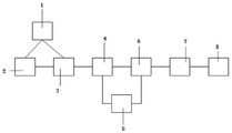
the invention relates to a rainwater collecting and discharging system for a green building, which comprises: the outlet end of the rainwater flow passage is connected with a scouring reservoir and a primary filtering water pool; the water outlet end of the scouring reservoir is positioned above the primary filtering water pool; the outlet end of the primary filtering water tank is connected with a rainwater filtering and precipitating tank, and a rainwater discarding device is arranged between the primary filtering water tank and the rainwater filtering and precipitating tank; the rainwater discarding device is also connected with the rainwater filtering and precipitating tank through a rainwater purifying device; the outlet end of the rainwater filtering and precipitating tank is connected with a backflow tank, and a plurality of rainwater collecting tanks are arranged between the rainwater filtering and precipitating tank and the backflow tank.
Furthermore, a plurality of the rainwater collecting tanks are arranged in parallel or in series.
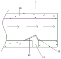
Furthermore, the rainwater flow channel comprises a flow channel body which is obliquely arranged, one side of the flow channel body is provided with a branch flow channel, a filter screen is arranged at the inlet of the branch flow channel, and the filter screen is inclined towards the inner side of the flow channel body and forms an included angle of 10-30 degrees with the water flow direction; one side of the filter screen is fixed on the inner side wall of the runner body on one side of the branch runner inlet, and the other side of the filter screen is arranged on the inner side wall of the runner body on the other side of the branch runner inlet through a fixing plate.
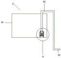
Furthermore, the scouring reservoir comprises a first reservoir body, a U-shaped drain pipe is arranged on the first reservoir body, one end of the U-shaped drain pipe extends to the bottom of the first reservoir body, and the other end of the U-shaped drain pipe is positioned outside the first reservoir body and is connected with a flushing pipe; the bottom of the first pool body is provided with a cut-off device communicated with the U-shaped drain pipe, the cut-off device comprises an inverted cylinder body, and the bottom end of the cylinder body is fixed at the bottom of the first pool body through a plurality of pillars;
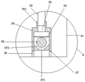
the opening end of the cylinder body is provided with a sealing plug, and a water inlet is formed in the sealing plug; the top of the cylinder is provided with an opening, and the opening is provided with a joint communicated with a U-shaped drain pipe; a porous screen plate is arranged in the cylinder body between the sealing plug and the opening, and a gravity floating ball is arranged in the cylinder body between the porous screen plate and the sealing plug; the water inlet comprises a first hole and a second hole which are communicated in sequence; the cross section of the first hole is isosceles trapezoid, and the cross section of the second hole is rectangular.
Further, the primary filter water tank comprises a second tank body, a filter plate is arranged on the second tank body, the filter plate comprises a horizontal section positioned in the middle, and an uphill section and a downhill section are symmetrically arranged on two sides of the horizontal section respectively;
a plurality of rows of first through holes are formed in the upward slope section along the water flow direction, a semicircular tube body A is arranged on any row of first through holes, and a plurality of first water filtering holes are formed in one side, close to the horizontal section, of the semicircular tube body A along the length direction of the semicircular tube body A;
a plurality of rows of second through holes are formed in the downward slope section along the water flow direction, a semicircular pipe body B is arranged on any row of second through holes, and a plurality of second water filtering holes are formed in one side, far away from the horizontal section, of the semicircular pipe body B along the length direction of the semicircular pipe body B;
wherein, the included angle between the ascending section and the horizontal section is 165-175 degrees; the flushing pipe is positioned at the slope bottom of the uphill section, and the included angle between the water outlet flow direction of the flushing pipe and the uphill section is 5-15 degrees.
Furthermore, the rainwater discarding device comprises a rainwater collecting pool, the rainwater discarding device is installed at the bottom of a drainage groove between the primary filtering water pool and the rainwater filtering and precipitating pool, and a drainage hole communicated with the rainwater collecting pool is formed in the bottom of the drainage groove; the top end of the rainwater collecting pool is provided with a neck communicated with the drain hole, and a water baffle is rotatably arranged on the neck through a rotating column; a water discharging hole is formed in the bottom of the rainwater collecting pool, a blocking block used for blocking the water discharging hole is arranged above the water discharging hole, and a truncated cone-shaped convex block matched with the water discharging hole is arranged at the bottom end of the blocking block; the bottom of the rainwater collecting pool, which is positioned on the peripheral side of the water discharging hole, is provided with a plurality of guide rods, and the blocking block is provided with guide through holes which are matched with the guide rods one by one; the top of the blocking block is connected with a pull rope which is fixed at the bottom end of the water baffle; the water baffle comprises an L-shaped plate body, and the end part of the bottom end of the L-shaped plate body is provided with an elastic seal matched with the side wall of the neck; the L-shaped plate body is provided with a through hole matched with the rotary column; two sides of the top of the L-shaped plate body are symmetrically provided with an arc-shaped water retaining flanging respectively; and a U-shaped surrounding edge matched with the two arc-shaped water retaining flanges is arranged at the bottom of the water drainage groove above the water drainage hole.
Further, the rainwater purification device comprises a tank body, and the top and the bottom of the tank body are respectively communicated with a water inlet pipe and a water outlet pipe; a medicament spray head is arranged at the inner top of the tank body; the interior bottom of the jar body sets up a backup pad, set gradually cotton filter layer, plastic granules filter layer, coarse sand filter layer, sponge filter layer and filtration steel wire net layer in the backup pad.
Furthermore, the rainwater collecting pool comprises a water storage tank, a plurality of partition plates are sequentially arranged on the water storage tank from bottom to top, the rainwater collecting pool also comprises a pipeline which sequentially penetrates through the partition plates and is vertical to the bottom of the water storage tank, and a circular hole is formed in the pipeline positioned on one side of any one partition plate; the top of the water storage tank is provided with a first water inlet hole matched with the pipeline, and the bottom of the water storage tank in the pipeline is provided with a first water outlet hole; a floating body which can move up and down along the pipeline is arranged in the pipeline.
Further, the rainwater filtering and settling tank and the backflow tank; the rainwater filtration and sedimentation tank comprises a third tank body, a filtration device is arranged at the top of the third tank body, a rectangular water pipe is arranged at the middle-layer water area of the third tank body, and the rectangular water pipe penetrates through three side walls of the tank body; one end of the rectangular water pipe positioned at the third tank body is sealed, and rectangular through holes are formed in the peripheral side of the rectangular water pipe; the upper side and the lower side of the rectangular water pipe are respectively provided with a U-shaped flow stabilizing plate, and two sides of the U-shaped flow stabilizing plate are provided with flow stabilizing flanges; the rainwater filtering and precipitating tank is communicated with the reflux tank through a rectangular water pipe.
Furthermore, a water tank is connected between the rainwater filtering and precipitating tank and the backflow tank, and a rainwater collecting tank is communicated with the bottom of the water tank.
The invention has the following beneficial effects:
1. according to the invention, the rainwater metal at the early stage of rainfall is collected and post-treated by the rainwater flow discarding device, so that the cost of medicament treatment is reduced, and the overall treatment efficiency is improved.
2. The invention can prevent the erosion of rainwater through water collection, water treatment and water storage, has the functions of energy storage and temperature regulation, saves energy, protects environment and realizes the effective utilization of rainwater resources.
3. According to the invention, through the filter plate arranged on the primary filter water tank and the scouring reservoir for performing water flow scouring on the filter plate, scum is prevented from being accumulated at the water inlet end of the filter plate to influence the filtering effect of the filter plate when the filter is used.
Of course, it is not necessary for any product in which the invention is practiced to achieve all of the above-described advantages at the same time.
Drawings
In order to more clearly illustrate the technical solutions of the embodiments of the present invention, the drawings used in the description of the embodiments will be briefly introduced below, and it is obvious that the drawings in the following description are only some embodiments of the present invention, and it is obvious for those skilled in the art that other drawings can be obtained according to the drawings without creative efforts.
FIG. 1 is a green building rainwater collection and drainage system of the present invention;
FIG. 2 is a schematic view of the structure of the rainwater flow channel of the present invention;
fig. 3 is a schematic view of a scour reservoir configuration in accordance with the present invention;
FIG. 4 is an enlarged view of a portion of FIG. 3;
FIG. 5 is a schematic view of the primary filter tank of the present invention;
FIG. 6 is an enlarged view of a portion of FIG. 5B;
FIG. 7 is a schematic view of the filter plate structure of the present invention;
FIG. 8 is a schematic view of the rainwater drainage device of the present invention in a drainage state;
FIG. 9 is a schematic view of the rainwater drainage device according to the present invention;
FIG. 10 is a schematic view of the structure of the drain tank of the present invention;
FIG. 11 is a schematic view of the water deflector of the present invention;
FIG. 12 is a schematic view of the rainwater purification device according to the present invention;
FIG. 13 is a schematic view of the installation structure of the rectangular water pipe and the U-shaped flow stabilizer of the present invention;
FIG. 14 is a schematic view of the structure of the rectangular water tube and the U-shaped flow stabilizer of the present invention;
fig. 15 is a schematic structural view of the rainwater collection tank of the present invention.
Detailed Description
The technical solutions in the embodiments of the present invention will be clearly and completely described below with reference to the drawings in the embodiments of the present invention, and it is obvious that the described embodiments are only a part of the embodiments of the present invention, and not all of the embodiments. All other embodiments, which can be derived by a person skilled in the art from the embodiments given herein without making any creative effort, shall fall within the protection scope of the present invention.
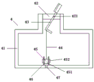
Referring to fig. 1 to 15, the present invention relates to a rainwater collecting and draining system for green buildings, comprising: the outlet end of the rainwater flow passage 1 is connected with a scouring reservoir 2 and a primary filtering water tank 3; the water outlet end of the scouring reservoir 2 is positioned above the primary filtering water tank 3; the outlet end of the primary filter water tank 3 is connected with a rainwater filtering and precipitating tank 6, and a rainwater discarding device 4 is arranged between the primary filter water tank 3 and the rainwater filtering and precipitating tank 6; the rainwater discarding device 4 is also connected with a rainwater filtering and precipitating tank 6 through a rainwater purifying device 5; the outlet end of the rainwater filtering and precipitating tank 6 is connected with a backflow tank 8, and a plurality of rainwater collecting tanks 7 are arranged between the rainwater filtering and precipitating tank 6 and the backflow tank 8.
Preferably, a plurality of rainwater collecting tanks 7 are arranged in parallel or in series.
Preferably, the rainwater flow channel 1 comprises a flow channel body 10 which is obliquely arranged, one side of the flow channel body 10 is provided with a branch flow channel 11, a filter screen 12 is arranged at a flow inlet of the branch flow channel 11, the filter screen 12 is inclined towards the inner side of the flow channel body 10, and an included angle between the filter screen 12 and the water flow direction is 10-30 degrees; one side of the filter screen 12 is fixed on the inner side wall of the flow channel body 10 at one side of the inlet of the branch flow channel 11, and the other side of the filter screen 12 is fixed on the inner side wall of the flow channel body 10 at the other side of the inlet of the branch flow channel 11 through a fixing plate 13.
Preferably, the flushing reservoir 2 comprises a first tank body 21, a U-shaped drain pipe 22 is arranged on the first tank body 21, one end of the U-shaped drain pipe 22 extends to the bottom of the first tank body 21, and the other end of the U-shaped drain pipe 22 is located outside the first tank body 21 and is connected with a flushing pipe 23; the bottom of the first tank body 21 is provided with a cut-off device communicated with the U-shaped drain pipe 22, the cut-off device comprises an inverted cylinder 24, and the bottom end of the cylinder 24 is fixed at the bottom of the first tank body 21 through a plurality of pillars 26;
a sealing plug 27 is arranged at the opening end of the cylinder 24, and a water inlet is arranged on the sealing plug 27; the top of the cylinder 24 is provided with an opening 25, and the opening 25 is provided with a joint 251 communicated with the U-shaped drain pipe 22; a porous screen plate 29 is also arranged in the cylinder body 24 between the sealing plug 27 and the opening 25, and a gravity floating ball 28 is also arranged in the cylinder body 24 between the porous screen plate 29 and the sealing plug 27; the water inlet comprises a first hole 272 and a second hole 271 which are communicated in sequence; the cross section of the first hole 272 is an isosceles trapezoid, and the cross section of the second hole 271 is a rectangle.
Preferably, the primary filter water tank 3 comprises a second tank body 30, a filter plate is arranged on the second tank body 30, the filter plate comprises a horizontal section 31 positioned in the middle, and an ascending section 32 and a descending section 33 are symmetrically arranged on two sides of the horizontal section 31 respectively;
a plurality of rows of first through holes 34 are formed in the upward slope section 32 along the water flow direction, a semicircular tube body A36 is arranged on any row of first through holes 34, and a plurality of first water filtering holes 38 are formed in one side, close to the horizontal section 31, of the semicircular tube body A36 along the length direction of the semicircular tube body;
a plurality of rows of second through holes 35 are formed in the downward slope section 33 along the water flow direction, a semicircular tube body B37 is arranged on any row of second through holes 34, and a plurality of second water filtering holes 39 are formed in one side, far away from the horizontal section 31, of the semicircular tube body B37 along the length direction of the semicircular tube body;
wherein, the included angle between the ascending section 32 and the horizontal section 31 is 165-175 degrees; the flushing pipe 23 is positioned at the slope bottom of the uphill section 32, and the included angle between the water flow direction of the flushing pipe 23 and the uphill section 32 is 5-15 degrees.
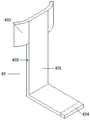
Preferably, the rainwater discarding device 4 comprises a rainwater collecting tank 41, the rainwater discarding device 4 is installed at the bottom of a drainage groove 40 between the primary filtering water tank 3 and the rainwater filtering and precipitating tank 6, and the bottom of the drainage groove 40 is provided with a drainage hole 401 communicated with the rainwater collecting tank 41; the top end of the rainwater collecting tank 41 is provided with a neck part 42 communicated with the drainage hole 401, and a water baffle 43 is rotatably arranged on the neck part 42 through a rotary column 421; a water discharging hole 47 is arranged at the bottom of the rainwater collecting pool 41, a blocking block 45 used for blocking the water discharging hole 47 is arranged above the water discharging hole 47, and a truncated cone-shaped convex block 451 matched with the water discharging hole 47 is arranged at the bottom end of the blocking block 45; the bottom of the rainwater collecting pool 41 positioned on the peripheral side of the water discharging hole 47 is provided with a plurality of guide rods 46, and the blocking block 45 is provided with guide through holes 452 which are matched with the guide rods 46 one by one; the top of the block 45 is connected with a pull rope 44, and the pull rope 44 is fixed at the bottom end of the water baffle 43; the water baffle 43 comprises an L-shaped plate body 431, and an elastic seal 434 matched with the side wall of the neck 42 is arranged at the bottom end part of the L-shaped plate body 431; the L-shaped plate 431 is provided with a through hole 432 matched with the rotary column 421; two arc-shaped water retaining flanges 433 are symmetrically arranged on two sides of the top of the L-shaped plate body 431 respectively; the bottom of the drainage groove 40 above the drainage hole 401 is provided with a U-shaped surrounding edge 402 matched with the two arc-shaped water retaining flanges 433.
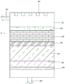
Preferably, the rainwater purification device 5 comprises a tank 51, and the top and the bottom of the tank 51 are respectively communicated with a water inlet pipe 52 and a water outlet pipe 53; a medicament spray head 58 is arranged at the inner top of the tank body 51; a supporting plate 50 is arranged at the inner bottom of the tank body 51, and a cotton cloth filtering layer 59, a plastic particle filtering layer 57, a coarse sand filtering layer 56, a sponge filtering layer 55 and a filtering steel wire mesh layer 54 are sequentially arranged on the supporting plate 50.
Preferably, the rainwater collecting tank 7 comprises a water storage tank 71, a plurality of partition plates 72 are sequentially arranged on the water storage tank 71 from bottom to top, a pipeline 73 which sequentially penetrates through the partition plates 72 and is vertical to the bottom of the water storage tank 71 is further included, and a circular hole 74 is formed in the pipeline 73 positioned on one side of any partition plate 72; the top of the water storage tank 71 is provided with a first water inlet hole 77 matched with the pipeline 73, and the bottom of the water storage tank 71 in the pipeline 73 is provided with a first water outlet hole 76; a float 75 is disposed within the conduit 73 to move up and down the conduit 73.
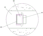
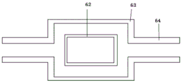
Preferably, the rainwater filtering and settling tank 6 and the return tank 8; the rainwater filtering and settling tank 6 comprises a third tank body 61, a filtering device is arranged at the top of the third tank body 61, a rectangular water pipe 62 is arranged at the middle-layer water area of the third tank body 61, and the rectangular water pipe 62 penetrates through the side wall of the third tank body 61; one end of the rectangular water pipe 62 positioned at the third tank body 61 is sealed, and a rectangular through hole is formed in the peripheral side of the rectangular water pipe; a U-shaped flow stabilizing plate 63 is respectively arranged at the upper side and the lower side of the rectangular water pipe 62, and flow stabilizing flanges 64 are arranged at the two sides of the U-shaped flow stabilizing plate 63; the rainwater filtering and settling tank 6 is communicated with the return tank 8 through a rectangular water pipe 62.
Preferably, a water tank is connected between the rainwater filtering and precipitating tank 6 and the backflow tank 8, and a rainwater collecting tank 7 is communicated with the bottom of the water tank.
In operation, in rainy days, rainwater gathered through the rainwater flow channel 1 flows into the primary filtering water tank 3 through the rainwater flow channel 1, when the rainwater passes through a filtering plate on the primary filtering water tank 3, large-sized floating slag such as leaves, plastic bags, wood blocks and the like in the rainwater is attached to the ascending section 32, the rainwater enters the second tank body 30 through the first water filtering holes 38 and the first through holes 34, meanwhile, the rainwater passes through the branch flow channel 11 on one side of the rainwater flow channel 1 and enters the scouring water tank 2 through the filtering screen 12, when the water level in the scouring water tank 2 submerges the top end of the U-shaped drainage pipe 22, the rainwater in the scouring water tank 2 is rapidly discharged through the flushing pipe 23 of the U-shaped drainage pipe 22, and a high-speed water flow is formed, and impacts the surface of the ascending section 32, so as to drive the floating slag attached to the ascending section 32 to impact the horizontal section 31 under the action of the water flow, and flows into the downhill section 33 along the horizontal section 31, and simultaneously the rainwater flowing into the downhill section 33 sequentially enters the flushing reservoir 2 through the second water filtering holes 39 and the second through holes 35.
The second water filtering hole 39 and the first water filtering hole 38 are arranged on the water flow impact back surfaces of the semicircular tube body B37 and the semicircular tube body A36, so that under the action of water flow, sundries slightly larger than the diameters of the second water filtering hole 39 and the first water filtering hole 38 can pass through the second water filtering hole 39 and the first water filtering hole 38 to enter the semicircular tube body B37 and the semicircular tube body A36 or the sundries are blocked at the positions of the second water filtering hole 39 and the first water filtering hole 38; meanwhile, through the arrangement, when rainwater erosion is reduced, particles such as sand contained in rainwater enter the erosion reservoir 2, and the particles such as sand contained in rainwater are conveniently deposited at the intersection of the water flow impact back of the semicircular pipe body B37 and the semicircular pipe body A36, the uphill section 32 and the downhill section 33.
The flushing reservoir 2 is used for carrying out early-stage water storage, and then high-speed water flow is formed by siphoning and discharged under the action of the U-shaped drain pipe 22; when the water in the flushing reservoir 2 is discharged to the rated height, the gravity floating ball 28 descends along with the water level and is blocked at the water inlet, at the moment, the water in the flushing reservoir 2 cannot enter the barrel body 24 through the water inlet, namely, the water cannot enter the U-shaped drain pipe 22 to be discharged, when the water level rises along with the water level, when the gravity floating ball 28 is completely submerged, the gravity floating ball 28 is abutted against the porous net plate 29, at the moment, the water in the flushing reservoir 2 enters the barrel body 24 through the water inlet and enters the U-shaped drain pipe 22, and at the moment, the water in the U-shaped drain pipe 22 is located and level in the flushing reservoir 2.
When water in the primary filtering water tank 3 is discharged onto the drainage channel 40 through a water outlet at the bottom of the primary filtering water tank 3, because under the action of the self gravity of the L-shaped plate body 431, a gap is formed between the elastic seal 434 and the neck 42, rainwater enters the rainwater collection tank 41 through the gap, when the water level of the rainwater collection tank 41 rises to a certain height and submerges the bottom end of the L-shaped plate body 431, the L-shaped plate body 431 is subjected to the buoyancy action of the water and along with the action force of rainwater impacting the L-shaped plate body 431, the elastic seal 434 at the bottom end of the L-shaped plate body 431 is abutted against the side wall of the neck 42 to form a seal, and the rainwater cannot enter the rainwater collection tank 41 through the gap; meanwhile, under the diversion effect of the arc-shaped water retaining flanging 433, rainwater is discharged through the water grooves 40 on two sides of the arc-shaped water retaining flanging 433, shielding is formed under the effect of the U-shaped surrounding edge 402, and the U-shaped surrounding edge 402 abuts against the back water surface of the L-shaped plate body 431 and the arc-shaped water retaining flanging 433 to form sealing.
Meanwhile, when no water flows in the drainage groove 40, the L-shaped plate 431 does not receive rainwater impact force at the moment, the L-shaped plate 431 rotates along the rotary column 421 under the action of self gravity at the moment, one end of the connection pull rope 44 rises at the moment, the pull rope 44 rises to drive the blocking block 45 to be separated from the water discharging hole 47, rainwater in the rainwater collecting pool 41 is discharged through the water discharging hole 47, the discharging process is along with the descending of the water level, the L-shaped plate 431 rotates along the rotary column 421 under the action of self gravity, one end of the connection pull rope 44 descends at the moment, and at the moment, under the guiding action of the guide rod 46, the blocking block 45 slowly descends along the guide rod 46 and blocks the water discharging hole 47.
The polluted rainwater entering the tank body 51 is sprayed with the medicament through the medicament spray head 58, and the medicament is mixed with the polluted rainwater, and then the mixing degree and mixing time of the rainwater and the medicament are enhanced through the laminar flow effect of the filtering steel wire mesh layer 54, the sponge filter layer 55, the coarse sand filter layer 56 and the plastic particle filter layer 57, so that heavy metal, grease and the like contained in the rainwater are combined into large-particle pollutants; meanwhile, the cotton cloth filter layer 59 filters large-particle pollutants, so that a water purification effect is achieved. The purified water is discharged into a rainwater filtering and precipitating tank 6, and is precipitated together with rainwater at the later stage of precipitation, and is discharged into a rainwater collecting tank 7 under the action of a water tank, the water overflowing from the rainwater collecting tank 7 enters a backflow tank 8, and the water in the backflow tank 8 is pumped back into the rainwater filtering and precipitating tank 6.
According to the invention, the partition plate 72, the pipeline 73 and the floating body 75 are arranged in the water storage tank 71, so that the contact of rainwater entering the water storage tank 71 with the outside is reduced during storage, the volatilization speed is reduced, and the requirement of water body storage is met. Meanwhile, a rectangular water pipe 62 and a U-shaped flow stabilizing plate 63 are arranged in the rainwater filtering and settling tank 6; so that the rainwater settled in the rainwater filtering and settling tank 6 can be discharged through the rectangular water pipe 62 under the effect of not influencing the whole water flow, and the sediment deposited at the bottom due to the disturbance of the water flow in the whole water area is prevented from being sucked into the rectangular water pipe 62 and discharged.
It should be noted that, in the above system embodiment, each included unit is only divided according to functional logic, but is not limited to the above division as long as the corresponding function can be implemented; in addition, specific names of the functional units are only for convenience of distinguishing from each other, and are not used for limiting the protection scope of the present invention.
In addition, it can be understood by those skilled in the art that all or part of the steps in the method for implementing the embodiments described above can be implemented by instructing the relevant hardware through a program, and the corresponding program can be stored in a computer-readable storage medium, such as a ROM/RAM, a magnetic disk, an optical disk, or the like.
The preferred embodiments of the invention disclosed above are intended to be illustrative only. The preferred embodiments are not intended to be exhaustive or to limit the invention to the precise embodiments disclosed. Obviously, many modifications and variations are possible in light of the above teaching. The embodiments were chosen and described in order to best explain the principles of the invention and the practical application, to thereby enable others skilled in the art to best utilize the invention. The invention is limited only by the claims and their full scope and equivalents.
Claims (9)
1. The utility model provides a green building rainwater is collected and drainage system which characterized in that includes: the outlet end of the rainwater flow channel (1) is connected with a scouring reservoir (2) and a primary filtering water pool (3); the water outlet end of the scouring reservoir (2) is positioned above the primary filtering water pool (3);
the outlet end of the primary filter water tank (3) is connected with a rainwater filtering and precipitating tank (6), and a rainwater discarding device (4) is arranged between the primary filter water tank (3) and the rainwater filtering and precipitating tank (6); the rainwater discarding device (4) is also connected with a rainwater filtering and precipitating tank (6) through a rainwater purifying device (5);
the outlet end of the rainwater filtering and settling tank (6) is connected with a backflow tank (8), and a plurality of rainwater collecting tanks (7) are arranged between the rainwater filtering and settling tank (6) and the backflow tank (8);
the scouring reservoir (2) comprises a first pool body (21), a U-shaped drain pipe (22) is arranged on the first pool body (21), one end of the U-shaped drain pipe (22) extends to the bottom of the first pool body (21), and the other end of the U-shaped drain pipe (22) is located outside the first pool body (21) and is connected with a flushing pipe (23);
the bottom of the first tank body (21) is provided with a cut-off device communicated with the U-shaped drain pipe (22), the cut-off device comprises an inverted cylinder body (24), and the bottom end of the cylinder body (24) is fixed at the bottom of the first tank body (21) through a plurality of pillars (26);
a sealing plug (27) is arranged at the opening end of the cylinder body (24), and a water inlet is formed in the sealing plug (27);
the top of the cylinder body (24) is provided with an opening (25), and a joint (251) communicated with the U-shaped drain pipe (22) is arranged at the opening (25);
a porous screen plate (29) is also arranged in the cylinder body (24) between the sealing plug (27) and the opening (25), and a gravity floating ball (28) is also arranged in the cylinder body (24) between the porous screen plate (29) and the sealing plug (27);
the water inlet comprises a first hole (272) and a second hole (271) which are communicated in sequence;
the cross section of the first hole (272) is isosceles trapezoid, and the cross section of the second hole (271) is rectangular.
2. A green building rainwater collection and drainage system according to claim 1 wherein a plurality of said rainwater collection tanks (7) are arranged in parallel or in series.
3. A green building rainwater collecting and discharging system according to claim 1, wherein the rainwater flow channel (1) comprises a channel body (10) which is obliquely arranged, one side of the channel body (10) is provided with a branch flow channel (11), a filter screen (12) is arranged at the inlet of the branch flow channel (11), and the filter screen (12) is inclined towards the inner side of the channel body (10) and forms an angle of 10-30 degrees with the water flow direction; one side of the filter screen (12) is fixed on the inner side wall of the runner body (10) on one side of the flow inlet of the branch runner (11), and the other side of the filter screen (12) is fixed on the inner side wall of the runner body (10) on the other side of the flow inlet of the branch runner (11) through a fixing plate (13).
4. A green building rainwater collecting and discharging system according to claim 1, wherein said primary filtering water tank (3) comprises a second tank body (30), said second tank body (30) is provided with a filtering plate, said filtering plate comprises a horizontal section (31) in the middle, and both sides of said horizontal section (31) are symmetrically provided with an ascending section (32) and a descending section (33), respectively;
a plurality of rows of first through holes (34) are formed in the upward slope section (32) along the water flow direction, a semicircular tube body A (36) is arranged on any row of the first through holes (34), and a plurality of first water filtering holes (38) are formed in one side, close to the horizontal section (31), of the semicircular tube body A (36) along the length direction of the semicircular tube body;
a plurality of rows of second through holes (35) are formed in the downward slope section (33) along the water flow direction, a semicircular tube body B (37) is arranged on any row of second through holes (34), and a plurality of second water filtering holes (39) are formed in one side, far away from the horizontal section (31), of the semicircular tube body B (37) along the length direction of the semicircular tube body;
wherein the included angle between the ascending section (32) and the horizontal section (31) is 165-175 degrees;
the flushing pipe (23) is positioned at the slope bottom of the uphill section (32), and the included angle between the water flow direction of the flushing pipe (23) and the uphill section (32) is 5-15 degrees.
5. A green building rainwater collecting and discharging system according to claim 1, wherein said rainwater discarding apparatus (4) comprises a rainwater collecting tank (41), said rainwater discarding apparatus (4) is installed at the bottom of a drainage channel (40) between the primary filtering water tank (3) and the rainwater filtering and settling tank (6), and the bottom of the drainage channel (40) is provided with a drainage hole (401) communicated with the rainwater collecting tank (41);
the top end of the rainwater collecting pool (41) is provided with a neck part (42) communicated with the drainage hole (401), and a water baffle (43) is rotatably arranged on the neck part (42) through a rotary column (421);
a water discharging hole (47) is formed in the bottom of the rainwater collecting pool (41), a blocking block (45) used for blocking the water discharging hole (47) is arranged above the water discharging hole (47), and a truncated cone-shaped convex block (451) matched with the water discharging hole (47) is arranged at the bottom end of the blocking block (45); a plurality of guide rods (46) are arranged at the bottom of the rainwater collecting pool (41) positioned on the peripheral side of the water discharging hole (47), and guide through holes (452) which are matched with the guide rods (46) one by one are arranged on the blocking block (45); the top of the blocking block (45) is connected with a pull rope (44), and the pull rope (44) is fixed at the bottom end of the water baffle (43);
the water baffle (43) comprises an L-shaped plate body (431), and an elastic seal (434) matched with the side wall of the neck (42) is arranged at the bottom end part of the L-shaped plate body (431); the L-shaped plate body (431) is provided with a through hole (432) matched with the rotary column (421); two sides of the top of the L-shaped plate body (431) are symmetrically provided with an arc-shaped water retaining flanging (433) respectively;
the bottom of the drainage groove (40) above the drainage hole (401) is provided with a U-shaped surrounding edge (402) matched with the two arc-shaped water-retaining flanges (433).
6. A green building rainwater collecting and discharging system according to claim 1, wherein said rainwater purification device (5) comprises a tank (51), the top and bottom of said tank (51) are respectively communicated with a water inlet pipe (52) and a water outlet pipe (53);
a medicament spray head (58) is arranged at the inner top of the tank body (51);
the interior bottom of the tank body (51) is provided with a supporting plate (50), and a cotton cloth filtering layer (59), a plastic particle filtering layer (57), a coarse sand filtering layer (56), a sponge filtering layer (55) and a filtering steel wire mesh layer (54) are sequentially arranged on the supporting plate (50).
7. The green building rainwater collecting and discharging system according to claim 1, wherein the rainwater collecting tank (7) comprises a water storage tank (71), a plurality of partition plates (72) are sequentially arranged on the water storage tank (71) from bottom to top, a pipeline (73) penetrates through the partition plates (72) in sequence and is vertical to the bottom of the water storage tank (71), and a circular hole (74) is formed in the pipeline (73) positioned on one side of any partition plate (72);
the top of the water storage tank (71) is provided with a first water inlet hole (77) matched with the pipeline (73), and the bottom of the water storage tank (71) positioned in the pipeline (73) is provided with a first water outlet hole (76);
a floating body (75) which can move up and down along the pipeline (73) is arranged in the pipeline (73).
8. A green building rainwater collection and drainage system according to claim 1 wherein said rainwater filtration and precipitation tank (6) and said return tank (8);
the rainwater filtering and settling tank (6) comprises a third tank body (61), a filtering device is arranged at the top of the third tank body (61), a rectangular water pipe (62) is arranged at the middle-layer water area of the third tank body (61), and the rectangular water pipe (62) penetrates through the side wall of the third tank body (61);
the rectangular water pipe (62) is positioned at one end of the tank body III (61) and is sealed, and rectangular through holes are formed in the peripheral side of the tank body III;
a U-shaped flow stabilizing plate (63) is respectively arranged at the upper side and the lower side of the rectangular water pipe (62), and flow stabilizing flanges (64) are arranged at the two sides of the U-shaped flow stabilizing plate (63);
the rainwater filtering and settling tank (6) is communicated with the backflow tank (8) through a rectangular water pipe (62).
9. A green building rainwater collection and discharge system according to claim 1, wherein a water tank is connected between the rainwater filtration and precipitation tank (6) and the return tank (8), and the bottom of the water tank is communicated with a rainwater collection tank (7).
Priority Applications (1)
| Application Number | Priority Date | Filing Date | Title |
|---|---|---|---|
| CN202010418031.4A CN111705866B (en) | 2020-05-18 | 2020-05-18 | Green building rainwater is collected and discharge system |
Applications Claiming Priority (1)
| Application Number | Priority Date | Filing Date | Title |
|---|---|---|---|
| CN202010418031.4A CN111705866B (en) | 2020-05-18 | 2020-05-18 | Green building rainwater is collected and discharge system |
Publications (2)
| Publication Number | Publication Date |
|---|---|
| CN111705866A CN111705866A (en) | 2020-09-25 |
| CN111705866B true CN111705866B (en) | 2021-01-05 |
Family
ID=72537216
Family Applications (1)
| Application Number | Title | Priority Date | Filing Date |
|---|---|---|---|
| CN202010418031.4A Active CN111705866B (en) | 2020-05-18 | 2020-05-18 | Green building rainwater is collected and discharge system |
Country Status (1)
| Country | Link |
|---|---|
| CN (1) | CN111705866B (en) |
Families Citing this family (3)
| Publication number | Priority date | Publication date | Assignee | Title |
|---|---|---|---|---|
| CN113374058A (en) * | 2021-07-16 | 2021-09-10 | 黄静 | Rainwater recycling equipment for building |
| CN113944209B (en) * | 2021-10-27 | 2023-05-09 | 山东省水利科学研究院 | Rainwater discarding device for rainwater collection and use method thereof |
| CN114396108B (en) * | 2022-01-18 | 2024-03-12 | 中国建筑第八工程局有限公司 | Sponge urban rainwater collection and purification treatment system |
Family Cites Families (5)
| Publication number | Priority date | Publication date | Assignee | Title |
|---|---|---|---|---|
| DE4202245A1 (en) * | 1991-06-06 | 1992-12-17 | Pfeiffer Stephan | DEVICE FOR BRANCHING RAINWATER FROM A GUTTER PIPE |
| CN207469397U (en) * | 2017-09-28 | 2018-06-08 | 中冶华天工程技术有限公司 | Rain sewage is regulated and stored processing system |
| CN210421244U (en) * | 2019-06-03 | 2020-04-28 | 湖北三宁化工股份有限公司 | Initial rainwater collecting and processing device |
| CN110258751A (en) * | 2019-06-22 | 2019-09-20 | 东莞市永庆市政服务有限公司 | A kind of municipal rainwater storage system |
| CN110185134B (en) * | 2019-06-28 | 2020-11-17 | 东阳市晖宏环境工程有限公司 | Garden sewage drainage ditch flushing device utilizing water storage and pressurization |
-
2020
- 2020-05-18 CN CN202010418031.4A patent/CN111705866B/en active Active
Also Published As
| Publication number | Publication date |
|---|---|
| CN111705866A (en) | 2020-09-25 |
Similar Documents
| Publication | Publication Date | Title |
|---|---|---|
| CN111705866B (en) | Green building rainwater is collected and discharge system | |
| CN105625545B (en) | A kind of region fragment rain processing system based on separate system pipe network | |
| CN105735449B (en) | A kind of urban road rainwater collecting and treating system | |
| CN105714913A (en) | Zone partition rainwater flow dividing treatment system based on separate system pipe network | |
| CN109797839B (en) | Urban road gutter inlet efficient sewage interception device and sewage interception operation method | |
| CN209353440U (en) | Road rain water suitable for sponge city stores heat-extraction system | |
| CN107585893A (en) | A kind of rainwater filtering device | |
| CN114991253A (en) | Rainwater purification regulation and storage system | |
| CN211817483U (en) | Automatic rainwater shunting and filtering bucket for building | |
| CN206385597U (en) | A kind of rainwater-collecting processing unit | |
| KR100699326B1 (en) | Rainwater processing unit and method | |
| WO2019061869A1 (en) | Integrated rainwater treatment device | |
| CN205475587U (en) | Regional burst rainwater reposition of redundant personnel processing system based on reposition of redundant personnel tubulation net | |
| CN205475588U (en) | Regional burst rainwater processing system based on reposition of redundant personnel tubulation net | |
| CN206529878U (en) | A kind of municipal drainage community storm detention tank | |
| CN212294975U (en) | Overflow well for sponge city construction | |
| CN107119781A (en) | A kind of automatic sewage collection system of urban flood control and drainage and method | |
| CN107806171A (en) | A kind of enhanced Rain Garden of integration | |
| CN113187022A (en) | Rainwater collection and discharge ecological system | |
| CN207121973U (en) | A kind of automatic sewage collection system of urban flood control and drainage | |
| CN112359944A (en) | Municipal drainage structure with non-point source rubbish filtering capability | |
| CN112031169A (en) | Assembled box type house with rainwater collecting function | |
| CN220686530U (en) | Roof rainwater collecting and recycling system | |
| CN212127904U (en) | Rainwater purification and collection system capable of automatically flushing | |
| CN215563194U (en) | Gutter inlet structure with initial rainwater purification function |
Legal Events
| Date | Code | Title | Description |
|---|---|---|---|
| PB01 | Publication | ||
| PB01 | Publication | ||
| SE01 | Entry into force of request for substantive examination | ||
| SE01 | Entry into force of request for substantive examination | ||
| TA01 | Transfer of patent application right | ||
| TA01 | Transfer of patent application right |
Effective date of registration: 20201218 Address after: Room 102, No. 4815, Lianxi Road, Jinze Town, Qingpu District, Shanghai, 201799 Applicant after: SHANGHAI YUANGOU DESIGN CONSULTING Co.,Ltd. Address before: 214000 Shenzhen Hong Kong Metropolis Plaza 10-1507, Xinwu District, Wuxi City, Jiangsu Province Applicant before: Wuxi Tada Electromechanical Technology Co.,Ltd. |
|
| GR01 | Patent grant | ||
| GR01 | Patent grant |