Disclosure of Invention
In order to solve the problems, the invention provides intelligent detection equipment based on weak current engineering.
The specific scheme is as follows:
based on intelligent check out test set of light current engineering, include
A feeding device is arranged on the base plate,
a detection conveying system formed by a plurality of continuously connected feeding modules,
an optical detection device, at least one element single-pulling device, a sorting and discharging device, a full-pulling device and a control device which are arranged along the detection conveying system in sequence,
the control device comprises a driving module, a communication interface, an image detector and a processor,
the driving module sends a feeding driving signal to a feeding motor arranged on the feeding device, the feeding motor drives a motor shaft to drive the linkage bracket to send the multi-station electronic element detection strip in the discharging groove into the feeding suction head from the discharging groove,
the feeding suction head is contacted with the multi-station electronic element detection strip and sends a feeding feedback signal to the control device, when the control device receives the feeding feedback signal, the control device controls the driving module to drive the material suction cylinder to move forwards to drive the feeding suction head to suck the multi-station electronic element detection strip and move reversely to the contact sensor, the contact sensor sends a feeding contact signal to the control device, the control device controls the driving device to drive the feeding module to act to send the multi-station electronic element detection strip into the feeding module from the feeding end of the feeding module,
when the multi-station electronic component detection strip moves to the optical detection device, the control device controls the communication interface to send a detection signal to the optical detection device through the optical fiber transmission module, so that a camera arranged on the optical detection device shoots the multi-station electronic component detection strip, the image detector is connected with the camera and is used for inputting the shot image signal into the image detector, the image detector vertically splices the input image signal and an electronic template arranged in the image detector to form a simulation test chart, the electronic template is electrified and simulated to obtain a detection result, if the detection result comprises a failure simulation signal of at least one station, a failure simulation signal is sent to the processor, the processor processes the failure simulation signal to obtain the station data information corresponding to the failure simulation signal, and the station data information is transmitted to the control device, the control device receives the station data information and converts the station data information into a waste removal driving signal, the waste removal driving signal is transmitted to the element single-drawing device, the waste elements on the multi-station electronic element detection strip are drawn out by the element single-drawing device, the waste elements are collected by the sorting and discharging device, the rest multi-station electronic element detection strip is transmitted to the full-drawing device through the feeding module, the control device controls the driving module to drive the lower push plate cylinder on the full-drawing device to act to complete the full-drawing operation on the multi-station electronic element detection strip, and the single electronic element after full-drawing is discharged from a finished product discharging hopper to a finished product discharging groove through a discharging pipe.
Furthermore, the feeding device comprises a feeding bottom plate and a feeding groove arranged at the upper part of the feeding bottom plate, a group of turnover shaft assemblies are arranged at the lower part of the feeding bottom plate and at the back side of the feeding groove, the turnover shaft assemblies are connected with a motor shaft assembly of the feeding motor through a chain wheel,
the turnover shaft assembly comprises two turnover bearing seats which are correspondingly arranged, the turnover bearing seats are fixed at the bottom of the feeding bottom plate, a turnover shaft is arranged between the turnover bearing seats, linkage brackets are arranged at two sides of the turnover shaft, driven teeth are arranged on the turnover shaft between the turnover bearing seats,
the motor shaft assembly comprises a motor shaft, the motor shaft is arranged on the feeding motor, a driving tooth is arranged on the motor shaft, the driving tooth is connected with the driven tooth through a chain wheel,
the linkage bracket extends into the charging groove from a rotating notch arranged on the charging bottom plate,
a connecting optical axis is arranged between the two linked brackets, at least one group of discharging brackets are arranged on the connecting optical axis, a discharging adjusting strip fixed by the discharging brackets is arranged at each discharging bracket,
a feeding spacing ring which is arranged on the connecting optical axis and is positioned at the discharging adjusting strip and is used for adjusting the position of the discharging adjusting strip on the connecting optical axis,
the front end of the feeding groove is provided with a blanking notch,
a feeding cylinder is arranged on the feeding bottom plate at the front end of the feeding notch,
a cylinder rod of the feeding cylinder is provided with a feeding push block and a feeding blocking strip arranged in parallel with the feeding cylinder, the feeding blocking strip is arranged at the inner side of the feeding cylinder, the feeding push block is provided with a push block notch, the push block notch strides over the feeding blocking strip and is driven by the feeding cylinder to move left and right along the feeding blocking strip,
the material suction device is characterized in that a material suction cylinder bottom plate is arranged above the feeding material blocking strip and fixed on the feeding bottom plate through a support column, a material suction cylinder is arranged on the material suction cylinder bottom plate, a feeding suction head fixing plate is arranged on a push rod of the material suction cylinder, and at least one feeding suction head is arranged on the feeding suction head fixing plate.
Furthermore, the feeding module comprises a feeding module bottom plate, at least one group of feeding driving wheel sets arranged on the feeding module bottom plate, at least one compression roller is arranged between the feeding driving wheel sets,
a feeding motor which is arranged at the bottom of the bottom plate of the feeding module, a motor shaft of the feeding motor is provided with a feeding driving wheel, the feeding driving wheel is connected with a driven driving wheel arranged on one feeding driving wheel group through a feeding belt,
the feeding driving wheel set comprises a group of feeding bearing seats arranged on a bottom plate of the feeding module, feeding shafts arranged between the feeding bearing seats, a driving roller arranged on each feeding shaft,
two adjacent feeding driving wheel groups are connected by a feeding connecting wheel arranged on the feeding driving wheel groups through a connecting belt,
the pressure roller and the driving roller are arranged on the same axis,
the compression roller is fixed on a compression roller fixing seat, and the compression roller fixing seat is arranged on the feeding module bottom plate;
the driven driving wheel is arranged on the feeding shaft close to one end of the feeding driving wheel.
Further, the optical detection device comprises a camera mounting bracket,
the setting is provided with symmetrical last camera subassembly and lower camera subassembly at the upper end and the lower extreme of camera installing support, it is the same with lower camera subassembly structure to go up camera subassembly, all includes:
an inner vertical plate arranged at the upper end or the lower end of the camera mounting bracket, the inner vertical plate is fixed with the outer vertical plate through a connecting block, a camera fixing seat is arranged at the inner side of the upper end of the outer vertical plate, a camera is arranged on the camera fixing seat,
the upper end of the inner vertical plate is provided with a light source limiting frame, the upper part of the light source limiting frame is provided with a light source module which is coaxial with the camera,
the light source module is provided with a light source connecting block, the light source connecting block is provided with a light source connecting bracket, one end of the light source connecting bracket is fixed on the light source mounting vertical plate, the light source mounting vertical plate is provided with a light source module moving slide rail, the light source module moving slide rail is provided with a light source module moving slide block, the light source connecting bracket is fixed on the light source module moving slide block,
the light source module moving slide block fixing pin is arranged at the light source module moving slide block.
Furthermore, the element single-pulling device comprises an upper motor base and a lower fixed base which are butted up and down,
a single-pulling pushing cylinder is arranged above the upper motor base, a single-pulling cylinder push rod is arranged on the single-pulling pushing cylinder, a single-pulling cylinder push plate is arranged on the single-pulling cylinder push rod, a pulling cylinder fixing base is arranged on the single-pulling cylinder push plate, a pulling cylinder is arranged on the pulling cylinder fixing base, an upper pulling hand and a lower pulling hand are arranged on the pulling cylinder, rubber pressing blocks are respectively arranged at the butt joint ends of the upper pulling hand and the lower pulling hand,
a single-pull upper funnel and a single-pull lower funnel are arranged right below the upper pull hand and the lower pull hand,
the single-pull upper funnel is connected with the single-pull lower funnel.
Furthermore, the sorting and discharging device comprises a discharging base plate, a group of bearing supporting seats are respectively arranged at the left end and the right end of the discharging base plate, discharging bearing seats are arranged on the bearing supporting seats, a discharging shaft is arranged between each group of discharging bearing seats, discharging transmission teeth are arranged on the discharging shafts and connected through a discharging chain,
a plurality of discharge hoppers are arranged at the upper end of the discharge chain, wherein at least one discharge hopper is butted with the single-pull upper hopper before discharging,
the lower end of each discharging hopper is correspondingly provided with a discharging receiving hopper, the lower end of the discharging receiving hopper is provided with a receiving groove,
one side of the discharging substrate is provided with a discharging driving motor base, a discharging motor is arranged on the discharging driving motor base, a discharging driving wheel is arranged on a motor shaft of the discharging motor, and the discharging driving wheel is connected with a discharging driven wheel arranged on one discharging shaft through a discharging belt.
Further, the full-pulling device comprises a lower push plate seat, a group of lower guide blocks are arranged at the left end and the right end of the lower push plate seat, a guide rod fixing seat is arranged corresponding to the lower guide blocks and is positioned at the other end of the lower push plate seat,
the push rod is pulled out completely, one end of the lower guide block passes through the lower push plate seat and is fixed in the shaft hole of the guide rod fixing seat,
an upper guide block is arranged at the upper part of the lower guide block, the upper guide block and the lower guide block are connected through an upper guide rod and a lower guide rod, each lower guide block is provided with an upper push plate cylinder fixing seat, an upper push plate cylinder is arranged below the upper push plate cylinder fixing seat, an upper push rod is arranged on the upper push plate cylinder and is fixed with the upper guide block through a fisheye joint,
an upper push plate seat is fixed between the upper guide blocks,
the lower end of the upper push plate seat is provided with a lower positioning clamping opening,
the upper end of the lower push plate seat is provided with an upper positioning clamping opening,
the lower end of the lower positioning clamping opening and the upper end of the upper positioning clamping opening are respectively provided with a clamping opening rubber pressing strip,
and the lower push plate cylinder is arranged between the two lower guide blocks and is fixed with the lower push plate seat through a lower push rod.
The technical scheme of the invention has the following beneficial technical effects:
the optical fiber transmission module and the proximity sensor are arranged at the feeding device, the optical detection device, the element single-pulling device, the sorting and discharging device and the full-pulling device, an input circuit is divided into two paths, a control end adopts weak current, a power end adopts industrial electricity, and signal transmission is completed through the optical fiber transmission module.
The invention adopts a camera arranged on an optical detection device to shoot a multi-station electronic component detection strip, an image detector is connected with the camera and is used for inputting shot image signals into the image detector, all electronic components on the whole multi-station electronic component detection strip are shot in one-time shooting, the image detector is used for splicing the input image signals and an electronic template arranged in the image detector up and down, namely, the shot image is engraved on the electronic template, then a test pin connection is formed on the electronic template to form a simulation test pattern, the electronic template is electrified and simulated to obtain a detection result, a plurality of electronic components on the multi-station electronic component detection strip can be tested at one time, and the electronic component at which station fails to be tested is automatically identified.
Detailed Description
In order to make the objects, technical solutions and advantages of the present invention more apparent, the present invention will be described in further detail with reference to the accompanying drawings in conjunction with the following detailed description. It should be understood that the description is intended to be exemplary only, and is not intended to limit the scope of the present invention. Moreover, in the following description, descriptions of well-known structures and techniques are omitted so as to not unnecessarily obscure the concepts of the present invention.
As shown in fig. 1-10.
The invention provides a weak current engineering-based intelligent detection device, which comprises
The device comprises a box body 1, a feeding device 2 arranged at the upper end of the box body 1, a detection conveying system consisting of a plurality of continuously connected feeding modules 3, an optical detection device 5, at least one element single-drawing device 6, a sorting and discharging device 7, a full-drawing device 8 and a control device 4 which are sequentially arranged along the detection conveying system, wherein the control device 4 is arranged at the upper part of the box body and is positioned at one end of the feeding device 2,
sorting and discharging device 7 is arranged on the rear side of element single-pulling device 6 and inside box 1, power supply box 9 is arranged inside box 1, the input circuit is divided into two paths through power supply box 9, the control end adopts weak current, the power end adopts industrial electricity, and the transmission of signals is completed through optical fiber transmission modules.
The control device 4 comprises a driving module, a communication interface, an image detector and a processor,
the driving module sends a feeding driving signal to a feeding motor 119 arranged on the feeding device 2, the feeding motor 119 drives a motor shaft to drive the linkage bracket 100 to send the multi-station electronic element detection strip 106 in the discharging groove 101 into the feeding suction head 107 from the discharging groove 101,
the feeding suction head 107 is in contact with the multi-station electronic component detection strip 106 and sends a feeding feedback signal to the control device, when the control device 4 receives the feeding feedback signal, the control device 4 controls the driving module to drive the material suction cylinder 114 to move forward to drive the feeding suction head 107 to suck the multi-station electronic component detection strip 106 and move reversely to the contact sensor, the contact sensor sends a feeding contact signal to the control device 4, the control device 4 controls the driving device to drive the feeding module 3 to act, the multi-station electronic component detection strip 106 is fed from one feeding end of the feeding module 3,
when the multi-station electronic component detection strip 106 moves to the optical detection device 5, the control device 4 controls the communication interface to send a detection signal to the optical detection device 5 through the optical fiber transmission module, so that a camera 505 arranged on the optical detection device 5 shoots the multi-station electronic component detection strip 106, the image detector is connected with the camera 505 and is used for inputting the shot image signal into the image detector, the image detector splices the input image signal and an electronic template 13 arranged in the image detector up and down to form a simulation test chart, the electronic template 13 is electrified and simulated to obtain a detection result, if the detection result contains a failure simulation signal of at least one station, the failure simulation signal is sent to the processor, and the processor processes the failure simulation signal to obtain the station data information corresponding to the failure simulation signal, the multi-station electronic component detection device is characterized in that station data information is transmitted to a control device 4, the control device 4 receives the station data information and converts the station data information into a waste removal driving signal, the waste removal driving signal is transmitted to a component single-drawing device 6, the waste components on a multi-station electronic component detection strip are removed through the component single-drawing device 6, the waste components are collected through a sorting and discharging device 7, the rest multi-station electronic component detection strip 106 is transmitted to a full-drawing device 8 through a feeding module 3, the control device 4 controls the driving module to drive a lower push plate cylinder 802 on the full-drawing device 8 to act to complete full-drawing operation on the multi-station electronic component detection strip, and after full-drawing, a single electronic component is discharged from a finished product discharge hopper to a finished product discharge chute through a discharge pipe 10.
Referring to fig. 4 and 5, the feeding device 2 includes a feeding bottom plate 111, a feeding chute 101 disposed at an upper portion of the feeding bottom plate 111, a set of turnover shaft assemblies disposed at a lower portion of the feeding bottom plate 111 and at a back side of the feeding chute 101, the turnover shaft assemblies connected to a motor shaft assembly of the feeding motor 119 through a sprocket,
the turnover shaft assembly comprises two turnover bearing seats 116 which are correspondingly arranged, the turnover bearing seats 116 are fixed at the bottom of the feeding bottom plate 111, a turnover shaft 117 is arranged between the turnover bearing seats 116, linkage brackets 100 are arranged at two sides of the turnover shaft 117, driven teeth are arranged on the turnover shaft 117 between the turnover bearing seats 116,
the motor shaft assembly comprises a motor shaft, the motor shaft is arranged on a feeding motor 119, a driving tooth 120 is arranged on the motor shaft, the driving tooth 120 is connected with the driven tooth through a chain wheel,
the linkage bracket 100 extends into the upper trough 101 from a rotary notch 118 arranged on the feeding bottom plate 111,
a connecting optical axis 104 is arranged between the two linkage brackets 100, at least one group of discharging brackets 103 are arranged on the connecting optical axis 104, a discharging adjusting strip 102 fixed by the discharging brackets 103 is arranged at each discharging bracket 103,
the feeding spacing ring 105 is arranged on the connecting optical axis 104 and positioned at the discharging adjusting strip 102 and used for adjusting the position of the discharging adjusting strip 102 on the connecting optical axis 104 so as to be reasonably arranged for placing the multi-station electronic component detection strip 106,
the front end of the feeding groove 101 is provided with a discharging notch 115,
a feeding cylinder 110 is arranged on a feeding bottom plate 111 at the front end of the blanking notch 115,
a feeding push block 112 and a feeding blocking strip 113 arranged in parallel with the feeding cylinder 110 are arranged on a cylinder rod of the feeding cylinder 110, the feeding blocking strip 113 is arranged at the inner side of the feeding cylinder 110, the feeding push block 112 is provided with a push block notch, the push block notch crosses over the feeding blocking strip 113 and the feeding cylinder 110 drives the feeding push block 112 to move left and right along the feeding blocking strip 113,
a material suction cylinder bottom plate is arranged above the material feeding blocking strip 113, the material suction cylinder bottom plate is fixed on the material feeding bottom plate through a support column 109, a material suction cylinder 114 is arranged on the material suction cylinder bottom plate, a material feeding suction head fixing plate is arranged on a push rod of the material suction cylinder 114, and at least one material feeding suction head 117 is arranged on the material feeding suction head fixing plate 108.
When feeding, the driving module sends a feeding driving signal to the feeding motor 119, the feeding motor 119 acts to drive the feeding motor 119 to rotate the driving gear 120 arranged on the motor shaft, thereby driving the driven gear to rotate, the driven gear and the overturning shaft 117 rotate on the overturning bearing seat 116, thereby rotating the linkage bracket 100, the linkage bracket 100 drives the discharging bracket 103 to swing upwards, the lower part of the multi-station electronic component detection strip 106 is moved to the discharging notch 115, at this time, the feeding suction head 107 contacts the multi-station electronic component detection strip 106 and sends a feeding feedback signal to the control device, when the control device 4 receives the feeding feedback signal, the control device 4 controls the driving module to drive the feeding suction cylinder 114 to move forwards to drive the feeding suction head 107 to suck the multi-station electronic component detection strip 106 and move reversely to the contact sensor, and the contact sensor sends a feeding contact signal to the control device 4, the driving module of the control device 4 drives the feeding suction head 107 on the suction cylinder to lower the multi-station electronic component detection strip 106 to the inner side of the feeding stop strip 113,
the control device 4 controls the driving module to drive the feeding cylinder 110 to drive the feeding push block 112 to move leftwards along the feeding stop bar 113 to complete one-time feeding.
Referring to fig. 3, the feeding module 3 includes a feeding module base plate 200, at least one feeding driving wheel set disposed on the feeding module base plate 200, at least one pressing roller 206 disposed between the feeding driving wheel sets,
a feeding motor 209 arranged at the bottom of the feeding module base plate 200, a feeding driving wheel 201 arranged on a motor shaft of the feeding motor 209, the feeding driving wheel 201 connected with a driven driving wheel 204 arranged on one feeding driving wheel set through a feeding belt 203,
the feeding driving wheel set comprises a group of feeding bearing seats 202 arranged on the feeding module bottom plate 200, feeding shafts 207 arranged between the feeding bearing seats, a driving roller 208 arranged on each feeding shaft,
two adjacent feeding driving wheel groups are connected by a feeding connecting wheel arranged on the feeding driving wheel groups through a connecting belt,
the pressure roller and the driving roller are arranged on the same axis,
the compression roller is fixed on a compression roller fixing seat, and the compression roller fixing seat is arranged on the feeding module bottom plate;
the driven driving wheel is arranged on the feeding shaft close to one end of the feeding driving wheel;
during feeding, each section of feeding module 3 is controlled by the control device 4 to drive the feeding motor 209 to respectively move, the feeding motor 209 drives the feeding driving wheel 201 to rotate, the feeding driving wheel 201 drives the driven driving wheel 204 to rotate through the feeding belt 203, the driven driving wheel 204 drives the feeding shaft 207 to rotate, the feeding shaft 207 rotates and is connected with another feeding shaft 207 through the feeding connecting wheel and the connecting belt, and therefore the driving roller 208 drives the multi-station electronic component detection strip 106 to move.
Referring to fig. 6, the optical inspection device 5 includes a camera mounting bracket 500,
symmetrical upper and lower camera modules having the same structure are provided at the upper and lower ends of the camera mounting bracket 500.
Taking the above camera assembly as an example, the upper camera assembly includes:
an upper inner vertical plate disposed at the upper end of the camera mounting bracket 500,
the upper inner vertical plate is fixed with the upper outer vertical plate 502 through a connecting block, the inner side of the upper end of the upper outer vertical plate 502 is provided with a camera fixing seat 504, a camera 505 is arranged on the camera fixing seat,
the upper end of the upper inner vertical plate is provided with a light source limiting frame 503, the upper part of the light source limiting frame 503 is provided with a light source module 506 which is coaxial with the camera 505,
the light source module 506 is provided with a light source connecting block 507, the light source connecting block 507 is provided with a light source connecting bracket 508, one end of the light source connecting bracket 508 is fixed on a light source mounting vertical plate 511, the light source mounting vertical plate 511 is provided with a light source module moving slide rail 509, the light source module moving slide rail is provided with a light source module moving slide block 510, the light source connecting bracket is fixed on the light source module moving slide block,
a light source module moving slide block fixing pin 512 is arranged at the light source module moving slide block,
in the above, the light source module 506 is used for providing a shooting illumination environment for the camera 505 during shooting, the height of the light source module 506 can be adjusted by moving the light source module moving slide block 510 on the light source module moving slide rail 509, and the lowest end of the light source module is limited by the light source limiting frame 503.
Referring to fig. 7, the component single-pulling device 6 includes an upper base 601 and a lower base 600 which are butted up and down, the lower base 600 is fixed on the box body 1,
a single-pulling pushing cylinder 602 is arranged above the upper motor base 601, a single-pulling cylinder push rod 603 is arranged on the single-pulling pushing cylinder 602, a single-pulling cylinder push plate 604 is arranged on the single-pulling cylinder push rod 603, a pulling cylinder fixing base 605 is arranged on the single-pulling cylinder push plate 604, a pulling cylinder 606 is arranged on the pulling cylinder fixing base 605, an upper pulling hand 607 and a lower pulling hand 609 are arranged on the pulling cylinder 606, rubber pressing blocks 608 are respectively arranged at the butt ends of the upper pulling hand 607 and the lower pulling hand 609,
a single-pulling upper funnel 610 and a single-pulling lower funnel 611 are arranged right below the upper pulling hand 607 and the lower pulling hand 609,
the single-pull-up funnel 610 is connected with the single-pull-down funnel 611.
In the above, if the detection result received by the control device 4 includes a failure analog signal of at least one workstation, sending a failure simulation signal to the processor, processing the failure simulation signal by the processor to obtain the station data information corresponding to the failure simulation signal, transmitting the station data information to the control device 4, receiving the station data information by the control device 4 and converting the station data information into a waste product removing driving signal, and the waste removal driving signal is transmitted to the element single-pulling device 6, the control device 4 controls the driving module to drive the pulling cylinder 606 to act, the upper pulling hand 607 and the lower pulling hand 609 clamp the waste elements on the multi-station electronic element detection strip, the single-pulling pushing cylinder 602 pushes the pulling cylinder 606 to move backwards, the waste elements are pulled out, the waste elements are collected by the sorting and discharging device 7, and the rest multi-station electronic element detection strip 106 is transmitted to the full-pulling device 8 through the feeding module 3.
In the above, the upper pulling hand 607 and the lower pulling hand 609 are both provided with rubber pressing blocks 608, so that the electronic components are not damaged during pulling.
Referring to fig. 8, the sorting and discharging device 7 includes a discharging substrate 712, a set of bearing supporting seats 711 are respectively disposed at left and right ends of the discharging substrate 712, discharging bearing seats 710 are disposed on the bearing supporting seats 711, a discharging shaft 709 is disposed between each set of discharging bearing seats 710, discharging gear teeth 708 are disposed on the discharging shaft 709, the discharging gear teeth 708 are connected by a discharging chain 707,
a plurality of discharge hoppers 705 are arranged at the upper end of the discharge chain 707, wherein at least one discharge hopper 705 is butted with the single-pull upper hopper 610 before discharging,
the lower end of each discharging hopper 705 is correspondingly provided with a discharging receiving hopper 706, the lower end of the discharging receiving hopper is connected to a receiving groove 714 through a discharging pipeline 713,
a discharging driving motor seat 701 is arranged on one side of the discharging substrate 712, a discharging motor 700 is arranged on the discharging driving motor seat 701, a discharging driving wheel 702 is arranged on a motor shaft of the discharging motor 700, and the discharging driving wheel 702 is connected with a discharging driven wheel 704 arranged on one discharging shaft through a discharging belt 703.
When discharging is needed, the control device 4 controls the driving module to drive the discharging motor 700 to move, so as to drive the discharging driving wheel 702 on the motor shaft of the discharging motor 700 to rotate, the discharging driving wheel 702 drives the discharging driven wheel 704 to move through the discharging belt 703, so that the discharging shaft 709 rotates, the discharging chain 707 moves due to the rotation of the discharging shaft 709, and the discharging hopper 705 moves due to the movement of the discharging chain 707.
Referring to fig. 9, the full-pull apparatus 8 includes a lower push plate base 815, a set of lower guide blocks 800 disposed at left and right ends of the lower push plate base 815, a guide bar fixing base 805 disposed corresponding to the lower guide blocks 800 and located at the other end of the lower push plate base 815,
the push rod 801 is pulled down completely, one end of the lower guide block 800 passes through the lower push plate base 815 and is fixed in the shaft hole of the guide rod fixing base 805,
an upper guide block 807 is arranged at the upper part of the lower guide block 800, the upper guide block 807 and the lower guide block 800 are connected through an upper guide rod 808 and a lower guide rod 808, each lower guide block 800 is provided with a push-up plate cylinder fixing seat 803, a push-up plate cylinder 802 is arranged below the push-up plate cylinder fixing seat, an upper push rod is arranged on the push-up plate cylinder and is fixed with the upper guide block 807 through a fisheye joint 804,
an upper push plate seat 811 is fixed between the upper guide blocks 800,
the lower end of the upper push plate seat 811 is provided with a lower positioning nip 812,
the upper end of the lower push plate base 815 is provided with an upper positioning clip opening 814,
the lower end of the lower positioning clip 812 and the upper end of the upper positioning clip 814 are respectively provided with a clip rubber pressing strip 813,
and a lower push plate cylinder 809 arranged between the two lower guide blocks 800, wherein the lower push plate cylinder 809 is fixed with the lower push plate base 815 through a lower push rod 810.
When full-drawing is carried out, the control device 4 controls the driving module to drive the upper push plate cylinder 802 to act, the upper push rod moves upwards, the fisheye joint 804 drives the upper guide block 807 to move upwards on the upper and lower guide rods 808, so as to drive the upper push plate seat 811 to move upwards, the lower positioning clamping opening 812 is separated from the upper positioning clamping opening 814, the multi-station electronic component detection strip 106 moves to a position between the lower positioning clamping opening 812 and the upper positioning clamping opening 814, the control device 4 controls the driving module to drive the upper push plate cylinder 802 to act reversely, the lower positioning clamping opening 812 and the upper positioning clamping opening 814 clamp and pull out electronic components on the multi-station electronic component detection strip 106, the lower push plate seat 815 is pushed away from the original position by the lower push plate cylinder 809, the lower positioning clamping opening 812 and the upper positioning clamping opening 814 are staggered, and the electronic components are.
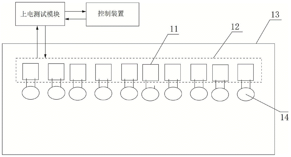
Referring to fig. 10, the present invention uses a camera 505 disposed on an optical detection device 5 to shoot a multi-position electronic component detection strip 106, an image detector is connected to the camera 505 for inputting a shot image signal into the image detector, when shooting at one time, all electronic components on the whole multi-position electronic component detection strip 106 are shot, the image detector vertically splices the input image signal with an electronic template disposed in the image detector, i.e. the shot image is imprinted on the electronic template 13, then the electronic template 13 is connected with a test pin 12 to form a simulated test pattern, the electronic template 13 is electrified and simulated by an electrification test module to obtain a detection result, which can test a plurality of electronic components 14 on the multi-position electronic component detection strip at one time, and which station fails to test the electronic components, and automatically recognizing. For example, if the test leads 12 of the electronic component 14 at 11 are not completely drawn on the electronic template 13, it is proved that the leads of the electronic component 14 are not complete in the image taken by the electronic template.
It is to be understood that the above-described embodiments of the present invention are merely illustrative of or explaining the principles of the invention and are not to be construed as limiting the invention. Therefore, any modification, equivalent replacement, improvement and the like made without departing from the spirit and scope of the present invention should be included in the protection scope of the present invention. Further, it is intended that the appended claims cover all such variations and modifications as fall within the scope and boundaries of the appended claims or the equivalents of such scope and boundaries.