CN111648936B - Cooling mechanism for rail transit control system - Google Patents
Cooling mechanism for rail transit control system Download PDFInfo
- Publication number
- CN111648936B CN111648936B CN202010554951.9A CN202010554951A CN111648936B CN 111648936 B CN111648936 B CN 111648936B CN 202010554951 A CN202010554951 A CN 202010554951A CN 111648936 B CN111648936 B CN 111648936B
- Authority
- CN
- China
- Prior art keywords
- cylinder
- stage
- intercooler
- air
- control system
- Prior art date
- Legal status (The legal status is an assumption and is not a legal conclusion. Google has not performed a legal analysis and makes no representation as to the accuracy of the status listed.)
- Active
Links
- 238000001816 cooling Methods 0.000 title claims abstract description 76
- 230000007246 mechanism Effects 0.000 title claims abstract description 24
- 238000007906 compression Methods 0.000 claims abstract description 93
- 230000006835 compression Effects 0.000 claims abstract description 91
- 238000009423 ventilation Methods 0.000 abstract description 4
- 239000012141 concentrate Substances 0.000 abstract description 3
- 230000000694 effects Effects 0.000 description 10
- 230000017525 heat dissipation Effects 0.000 description 10
- 238000000034 method Methods 0.000 description 9
- 230000008569 process Effects 0.000 description 6
- 238000012423 maintenance Methods 0.000 description 5
- 230000001788 irregular Effects 0.000 description 4
- 230000008859 change Effects 0.000 description 3
- 238000009434 installation Methods 0.000 description 3
- 238000005461 lubrication Methods 0.000 description 3
- 230000002411 adverse Effects 0.000 description 2
- 238000005253 cladding Methods 0.000 description 2
- 238000010586 diagram Methods 0.000 description 2
- 238000004519 manufacturing process Methods 0.000 description 2
- 230000002035 prolonged effect Effects 0.000 description 2
- 230000005855 radiation Effects 0.000 description 2
- 238000000926 separation method Methods 0.000 description 2
- 230000009286 beneficial effect Effects 0.000 description 1
- 230000005540 biological transmission Effects 0.000 description 1
- 230000007547 defect Effects 0.000 description 1
- 238000006073 displacement reaction Methods 0.000 description 1
- 238000003912 environmental pollution Methods 0.000 description 1
- 230000002349 favourable effect Effects 0.000 description 1
- 230000001050 lubricating effect Effects 0.000 description 1
- 238000005192 partition Methods 0.000 description 1
- 230000000750 progressive effect Effects 0.000 description 1
- 230000009467 reduction Effects 0.000 description 1
- 230000029058 respiratory gaseous exchange Effects 0.000 description 1
- 239000002699 waste material Substances 0.000 description 1
- XLYOFNOQVPJJNP-UHFFFAOYSA-N water Substances O XLYOFNOQVPJJNP-UHFFFAOYSA-N 0.000 description 1
- 230000003313 weakening effect Effects 0.000 description 1
Images



Classifications
-
- F—MECHANICAL ENGINEERING; LIGHTING; HEATING; WEAPONS; BLASTING
- F04—POSITIVE - DISPLACEMENT MACHINES FOR LIQUIDS; PUMPS FOR LIQUIDS OR ELASTIC FLUIDS
- F04B—POSITIVE-DISPLACEMENT MACHINES FOR LIQUIDS; PUMPS
- F04B35/00—Piston pumps specially adapted for elastic fluids and characterised by the driving means to their working members, or by combination with, or adaptation to, specific driving engines or motors, not otherwise provided for
- F04B35/04—Piston pumps specially adapted for elastic fluids and characterised by the driving means to their working members, or by combination with, or adaptation to, specific driving engines or motors, not otherwise provided for the means being electric
-
- F—MECHANICAL ENGINEERING; LIGHTING; HEATING; WEAPONS; BLASTING
- F04—POSITIVE - DISPLACEMENT MACHINES FOR LIQUIDS; PUMPS FOR LIQUIDS OR ELASTIC FLUIDS
- F04B—POSITIVE-DISPLACEMENT MACHINES FOR LIQUIDS; PUMPS
- F04B25/00—Multi-stage pumps
- F04B25/005—Multi-stage pumps with two cylinders
-
- F—MECHANICAL ENGINEERING; LIGHTING; HEATING; WEAPONS; BLASTING
- F04—POSITIVE - DISPLACEMENT MACHINES FOR LIQUIDS; PUMPS FOR LIQUIDS OR ELASTIC FLUIDS
- F04B—POSITIVE-DISPLACEMENT MACHINES FOR LIQUIDS; PUMPS
- F04B27/00—Multi-cylinder pumps specially adapted for elastic fluids and characterised by number or arrangement of cylinders
- F04B27/005—Multi-cylinder pumps specially adapted for elastic fluids and characterised by number or arrangement of cylinders with two cylinders
-
- F—MECHANICAL ENGINEERING; LIGHTING; HEATING; WEAPONS; BLASTING
- F04—POSITIVE - DISPLACEMENT MACHINES FOR LIQUIDS; PUMPS FOR LIQUIDS OR ELASTIC FLUIDS
- F04B—POSITIVE-DISPLACEMENT MACHINES FOR LIQUIDS; PUMPS
- F04B27/00—Multi-cylinder pumps specially adapted for elastic fluids and characterised by number or arrangement of cylinders
- F04B27/04—Multi-cylinder pumps specially adapted for elastic fluids and characterised by number or arrangement of cylinders having cylinders in star- or fan-arrangement
- F04B27/0404—Details, component parts specially adapted for such pumps
-
- F—MECHANICAL ENGINEERING; LIGHTING; HEATING; WEAPONS; BLASTING
- F04—POSITIVE - DISPLACEMENT MACHINES FOR LIQUIDS; PUMPS FOR LIQUIDS OR ELASTIC FLUIDS
- F04B—POSITIVE-DISPLACEMENT MACHINES FOR LIQUIDS; PUMPS
- F04B39/00—Component parts, details, or accessories, of pumps or pumping systems specially adapted for elastic fluids, not otherwise provided for in, or of interest apart from, groups F04B25/00 - F04B37/00
- F04B39/0094—Component parts, details, or accessories, of pumps or pumping systems specially adapted for elastic fluids, not otherwise provided for in, or of interest apart from, groups F04B25/00 - F04B37/00 crankshaft
-
- F—MECHANICAL ENGINEERING; LIGHTING; HEATING; WEAPONS; BLASTING
- F04—POSITIVE - DISPLACEMENT MACHINES FOR LIQUIDS; PUMPS FOR LIQUIDS OR ELASTIC FLUIDS
- F04B—POSITIVE-DISPLACEMENT MACHINES FOR LIQUIDS; PUMPS
- F04B39/00—Component parts, details, or accessories, of pumps or pumping systems specially adapted for elastic fluids, not otherwise provided for in, or of interest apart from, groups F04B25/00 - F04B37/00
- F04B39/06—Cooling; Heating; Prevention of freezing
- F04B39/066—Cooling by ventilation
Landscapes
- Engineering & Computer Science (AREA)
- Mechanical Engineering (AREA)
- General Engineering & Computer Science (AREA)
- Compressor (AREA)
Abstract
The invention relates to a cooling mechanism for a rail transit control system, comprising: the air compressor comprises an air compressor body, wherein the air compressor body comprises a motor (1), a crankshaft (12), a left row of compression cylinders, a right row of compression cylinders, a crankcase body (14) and pistons, wind scoopers (8) with centrifugal fans (85) are fixedly connected to the two ends of the air compressor body, and the centrifugal fans (85) and the crankcase body (14) are wrapped inside the wind scoopers (8) to cool a cylinder barrel and a cylinder cover. The cooling mechanism of the invention concentrates the cooling air sources of the cylinder barrel and the cylinder cover and the cooling air source of the intercooler on the fans at two ends of the whole air compressor, thus no motor is needed to be added and the control complexity is reduced; when the centrifugal fan cooling device works, the centrifugal fan (85) arranged at two ends of the crankcase body (14) and the corresponding air guide cover (8) form a centrifugal fan so as to increase air pressure, and the cooling of the cylinder barrel and the cylinder cover is realized through the air guide cover (8) and the ventilation channel arranged on the outer side of the cylinder barrel and the cylinder cover.
Description
Technical Field
The invention relates to the technical field of rail transit control, in particular to a cooling mechanism for a rail transit control system.
Background
An air compressor, i.e., an air compressor, is a device for compressing gas. Air compressors are classified into two types, namely speed type and volume type, and the volume type air compressors include reciprocating type (such as piston type) and rotary type (such as sliding vane type, screw type and rotor type). Most air compressors are of the reciprocating piston type, rotating blades (vanes) or rotating screws. The piston compressor is a positive displacement compressor, the compression element of which is a piston reciprocating in the cylinder of the piston air compressor. And can be divided into an oil-lubricated air compressor and an oil-free lubricated air compressor according to the lubrication mode.
What use in current track wind regime system field has oil piston air compressor machine, and current have oil piston air compressor machine still has following problem:
1. due to the adoption of the oil lubricating structure, the oil circuit structure is complex, the manufacturing precision of required parts is high, the production cost is high, the risk of oil leakage exists, and the environment is polluted.
2. In the working process, oil change and maintenance of gas post-treatment equipment (oil-gas separation, a dryer and the like) are required regularly, and in addition, waste polluting the environment is generated in the maintenance process, so that the maintenance is inconvenient.
3. The discharged gas contains oil, and along with the extension of working time, parts are abraded, the oil content is increased, and the service life of subsequent gas treatment equipment in the system is adversely affected.
4. The cooling structure is unreasonable, and the cooling structure in the prior art usually adopts two direct current fans installed at the bottom of the installation seat, and cooling air is blown to the other side from one side of the whole machine, so that additional power supply and control are required to be provided by the equipment.
For example, the utility model discloses a chinese utility model patent of grant bulletin number CN210460976U, it discloses an oil-free piston compressor of second grade compression, including the mount pad, fix the crankcase on the mount pad, fix on the mount pad and be located the motor of crankcase one side, fixed connection just is located the bent axle of crankcase in the epaxial and the motor power, fixes one-level cylinder and the second grade cylinder on the crankcase respectively, rotates one-level piston and the second grade piston of connection on the bent axle through the connecting rod respectively, and sealed lid closes one-level cylinder cap and the second grade cylinder cap on one-level cylinder and second grade cylinder respectively to and arrange the gas line on the mount pad. The utility model discloses an adopt the second grade compression, reduce the atress of air compressor machine structure, extension air compressor machine life, the second grade is compressed by the formula of going forward and is reduced single-stage compression power to set up interstage cooling structure and cool off, reduce the heat that air compressor machine compressed air produced. However, the cooling structure of the compressor adopts the direct current fan installed at the bottom for cooling, and cooling air is blown to the other side from one side of the whole machine, so that the equipment is required to provide control of an additional power supply, the occupied space is large, and the cooling effect is poor.
For another example, chinese patent application publication No. CN106837734A discloses a four-stage W-shaped high-pressure compressor, which comprises a compression system, a driving system, a power control system, a condensed water oil separation system and a cooling system, and adopts a four-stage three-cylinder design, wherein a primary cylinder and a secondary cylinder are integrated in a connected piston cylinder, thereby simplifying the mechanical structure, reducing the number of moving rods, saving the space, and improving the efficiency. The three-stage cylinder and the four-stage cylinder are respectively positioned at two sides of the connected cylinder of the first-stage cylinder and the second-stage cylinder, and the three cylinders are W-shaped; the heat radiating device is arranged outside each cylinder group, so that the compression process is close to isothermal compression, the density of compressed gas is increased, the enthalpy value is reduced after heat is released, the efficiency of compressed air is improved, the service life of the machine is prolonged, and the safety is improved. However, the compressor adopts an oil lubrication structure, the oil circuit structure is complex, the risk of oil leakage exists, and the discharged gas contains oil, so that the environmental pollution is caused; in addition, the maintenance of the post-treatment equipment for oil change and gas is inconvenient as the maintenance is required to be carried out regularly in the working process.
Disclosure of Invention
In order to solve the technical defects in the prior art, the invention aims to provide a cooling mechanism for a rail transit control system, which solves the problems that an oil lubrication structure adopted in the prior art is complex, the discharged gas contains oil, the cooling effect is poor, and the like.
In order to achieve the design purpose, the scheme adopted by the invention is as follows:
the invention provides a cooling mechanism for a rail transit control system, which comprises: the air compressor comprises an air compressor body, wherein the air compressor body comprises a motor, a crankshaft, a left row of compression cylinders, a right row of compression cylinders and a crankcase body fixedly connected to two ends of the motor 1, a piston is connected in the compression cylinders in a sliding mode, air guide covers of centrifugal fans are fixedly connected to two ends of the air compressor body, the centrifugal fans and the crankcase body are wrapped in the air guide covers, and cooling of a cylinder barrel and a cylinder cover is achieved.
The cooling mechanism of the invention concentrates the cooling air sources of the cylinder barrel and the cylinder cover and the cooling air source of the intercooler on the fans at two ends of the whole air compressor, thus no motor is needed to be added and the control complexity is reduced; when the cooling system works, a centrifugal fan is formed by the centrifugal fans arranged at the two ends of the crankcase body and the corresponding air guide covers so as to increase air pressure, and the cooling of the cylinder barrel and the cylinder cover is realized through the air guide covers and the ventilation channels arranged at the outer sides of the cylinder barrel and the cylinder cover; through the opening that the wind scooper set up at the box end, lead to some wind to the intercooler, realize the cooling to intercooler.
Preferably, the outer end of the crankshaft is fixedly connected with a fan shaft and is supported by a bearing mounted on the crankcase cover.
In any of the above schemes, preferably, the outer end of the fan shaft is fixedly connected with a fan hub, and the centrifugal fan is fixedly connected to the fan hub.
In any of the above schemes, preferably, an intercooler is arranged in the middle of one side of the air compressor body, and a part of air is guided to the intercooler through an opening arranged at the tail end of the crankcase body by the air guide cover, so that the intercooler is cooled.
In any of the above schemes, preferably, the wind scooper is barrel-shaped, and includes a cover wall, and the bottom end of the barrel-shaped cover is provided with an air inlet grille.
In any of the above aspects, it is preferable that the cover wall is spaced apart from an outer wall of the crankcase body by a second distance.
In any of the above schemes, preferably, the top of one end of the intercooler is provided with an intercooler inlet, and the vertical direction of the intercooler inlet is provided with an intercooler outlet.
In any of the above schemes, preferably, the left and right rows of compression cylinders include a first-stage compression cylinder and a second-stage compression cylinder, and the first-stage compression cylinder includes a first-stage cylinder barrel; the second-stage compression cylinder comprises a second-stage cylinder barrel.
In any of the above schemes, preferably, the inside of the first-stage compression cylinder and the two ends of the second-stage compression cylinder, which are located at the motor, are in a double-V layout.
In any of the above schemes, preferably, the intercooler is located on one side of a center axis of a V-shaped structure formed by the first-stage cylinder barrel and the second-stage cylinder barrel.
In any of the above schemes, preferably, a first-stage air inlet pipe and a second-stage air inlet pipe are arranged between the first-stage cylinder barrel and the second-stage cylinder barrel.
Clean air of this during operation at first gets into the sealed crankcase in both sides through one-level intake pipe, it is gaseous through setting up the admission valve entering one-level compression chamber at the piston top, gaseous get into the interstage cooling pipeline after the one-level compression, through the intercooler that sets up between the two-stage, one-level compressed gas is at the in-process through the intercooler, the heat of one-level compressed gas is fully dispersed in the air, thereby reduce the temperature of one-level compressed gas, realize interstage cooling, then get into the second grade compression chamber, discharge through the exhaust pipe after the second grade compression.
In any of the above schemes, preferably, the intercooler inlet is communicated with the exhaust port of the first-stage compression cylinder through a first-stage exhaust pipe; the intercooler outlet is communicated with the air inlet of the second-stage compression cylinder through a second-stage air inlet pipe.
In any of the above schemes, preferably, the first-stage cylinder barrel and the second-stage cylinder barrel are both provided with cylinder barrel outer covers, and a plurality of radiating fins are uniformly distributed at the end parts of the cylinder barrel outer covers.
In any of the above solutions, it is preferable that the cover wall has an opening adapted to the opening of the cylinder housing.
In any of the above schemes, it is preferable that the cooling of the first-stage cylinder barrel and the second-stage cylinder barrel and the cooling air source of the intercooler are concentrated on the centrifugal fans at both ends, and no motor is required to be added, thereby reducing the control complexity.
Drawings
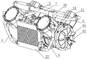
Fig. 1 is a schematic structural diagram for a rail transit control system according to the present invention.
Fig. 2 is a schematic structural view of a cooling mechanism in the preferred embodiment shown in fig. 1 for a rail transit control system according to the present invention.
Fig. 3 is a front view, half sectional view, in half, of the cooling mechanism of the preferred embodiment of fig. 2 for a rail transit control system in accordance with the present invention.
Fig. 4 is a rear view of the preferred embodiment of fig. 1 for a rail transit control system according to the present invention.
Fig. 5 is a side view of the preferred embodiment of fig. 1 for a rail transit control system in accordance with the present invention.
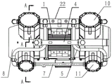
Fig. 6 is a bottom view of the preferred embodiment of fig. 1 for a rail transit control system in accordance with the present invention.
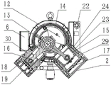
Fig. 7 is a sectional view taken in the direction of a-a of the preferred embodiment of fig. 6 for a rail transit control system according to the present invention.
Detailed Description
In order to more clearly illustrate the embodiments of the present invention or the technical solutions in the prior art, the drawings used in the description of the embodiments or the prior art will be briefly described below. It is obvious that the drawings in the following description are only some embodiments of the invention, from which other embodiments can be derived by a person skilled in the art without inventive effort.
As shown in fig. 1, the structure of the rail transit control system according to the invention is schematically shown. The invention provides a rail transit control system, which comprises:
the air compressor comprises an air compressor body, a compressor body and a control device, wherein the air compressor body comprises a motor 1, a crankshaft 12, a primary exhaust pipe 3 and a primary air inlet pipe 4;
both ends of the motor 1 are fixedly connected with a crankcase body 14, the side wall of the crankcase body 14 is fixedly connected with a left row of compression cylinders and a right row of compression cylinders which are vertical to an output shaft of the motor 1, and pistons are connected in the compression cylinders in a sliding manner;
the output shaft of the motor 1 is connected with a crankshaft 12 which drives the piston;
the two ends of the air compressor body are fixedly connected with air guide covers 8 with centrifugal fans arranged inside, so that cooling of the cylinder barrel and the cylinder cover is realized;
the intercooler 22 is arranged in the middle of one side of the air compressor body, and a part of air is guided to the intercooler through an opening formed in the tail end of the crankcase body 14 through the air guide cover 8, so that the intercooler is cooled.
In this embodiment, the left and right two rows of compression cylinders include two first-stage compression cylinders 10 on the left side and two second-stage compression cylinders 11 on the right side, and the first-stage compression cylinder 10 includes a first-stage cylinder barrel 29 and a first-stage cylinder head 2 which is sealed and covered on the first-stage cylinder barrel 29; the secondary compression cylinder 11 comprises a secondary cylinder barrel 30 and a secondary cylinder cover 19 which is sealed and covered on the secondary cylinder barrel 30.
Referring next to fig. 2 and 3, a schematic diagram of a cooling mechanism in the preferred embodiment of fig. 1 for a rail transit control system according to the present invention is shown.
The two ends of the air compressor body are fixedly connected with air guide covers 8 with centrifugal fans 85 arranged inside, and the centrifugal fans 85 and the crankcase body 14 are wrapped inside the air guide covers 8 to cool the cylinder barrel and the cylinder cover.
Because air compressor's both ends all are provided with centrifugal fan 85, so blow to about two strands of air currents of motor 1 central line department and will meet, and then form the diffusivity radiation air current that blows out to the motor 1 outside, partly in this air current will just in time meet with intercooler 22 that is located motor 1 one side to give intercooler 22 heat dissipation, strengthened intercooler 22's heat-sinking capability.
The cooling mechanism of the invention concentrates the cooling air source of the cylinder cover and the cooling air source of the intercooler 22 on the centrifugal fans 85 at two ends of the whole air compressor, thus needing no additional motor and reducing the control complexity; when the cooling system works, a centrifugal fan 85 arranged at two ends of the crankcase body and the corresponding air guide cover 8 form a centrifugal fan to increase air pressure, and the cooling system cools the cylinder barrel and the cylinder cover through the air guide cover 8 and ventilation channels arranged at the outer sides of the cylinder barrel and the cylinder cover; through the opening that the wind scooper 8 set up at the box end, lead some wind to intercooler 22, realize the cooling of intercooler 22.
In this embodiment, a fan shaft 82 is fixedly attached to the outer end of the crankshaft 12 and is supported by a bearing 83 mounted on a crankcase cover 81.
In this embodiment, the outer end of the fan shaft 82 is fixedly connected with a fan hub 84, and the centrifugal fan 85 is fixedly connected with the fan hub 84.
In this embodiment, an intercooler 22 is disposed in the middle of one side of the air compressor body, and a portion of air is guided to the intercooler through an opening formed in the tail end of the crankcase body 14 by the air guide cover 8, so as to cool the intercooler.
In this embodiment, the wind scooper 8 is barrel-shaped and includes a cover wall 86, and the bottom end of the barrel-shaped cover is provided with the air inlet grille 9.
In this embodiment, a second gap 87 is provided between the cover wall 86 and the outer wall of the crankcase body 14.
After the centrifugal fan 85 is driven by the crankshaft 12, cooling air flow enters the air guiding cover 8 from the air inlet grille 9, then reaches the inner side of the cover wall 86 through the centrifugal fan 85, then flows along the space 87 to cool the crankcase 14, and then flows out of the air guiding cover 8 to reach the shell of the motor 1, thereby cooling the motor 1.
The heat dissipation and cooling structure using the centrifugal fan 85 has the advantages that the heat dissipation related structure is small, the whole volume of the equipment is reduced, and the heat dissipation effect is relatively good due to the air flow cladding type cooling.
In this embodiment, an intercooler inlet 26 is disposed at the top of one end of the intercooler 22, and an intercooler outlet 27 is disposed in the vertical direction of the intercooler inlet 26.
In this embodiment, the left and right rows of compression cylinders include a first-stage compression cylinder interior 10 and a second-stage compression cylinder 11, and the first-stage compression cylinder 10 includes a first-stage cylinder barrel 29; the secondary compression cylinder 11 includes a secondary cylinder bore 30.
In this embodiment, the first-stage compression cylinder 10 and the second-stage compression cylinder 11 are located at two ends of the motor 1 and are in a double V-shaped layout.
In the present embodiment, the intercooler 22 is located on the side of the center axis of the V-shaped structure formed by the first-stage cylinder 29 and the second-stage cylinder 30.
In the present embodiment, a primary air inlet pipe 4 and a secondary air inlet pipe 5 are provided between the primary cylinder 29 and the secondary cylinder 30.
Clean air of this during operation gets into the sealed crankcase in both sides at first through one-level intake pipe, it is gaseous through setting up the admission valve entering one-level compression chamber at piston top, gaseous get into interstage cooling pipeline after the one-level compression, through the intercooler that sets up between the two-stage, one-level compressed gas is at the in-process through the intercooler, the heat of one-level compressed gas is fully dispelled in the air, thereby reduce the temperature of one-level compressed gas, realize interstage cooling, then get into the second grade compression chamber, discharge through the exhaust pipe after the second grade compression.
In the embodiment, the intercooler inlet 26 is communicated with the exhaust port of the first-stage compression cylinder 10 through the first-stage exhaust pipe 3; the intercooler outlet 27 communicates with the intake port of the second-stage compression cylinder 11 through the second-stage intake pipe 5.
In this embodiment, the first-stage cylinder 29 and the second-stage cylinder 30 are both provided with a cylinder cover 23, and a plurality of heat dissipation fins 25 are uniformly distributed at the end of the cylinder cover 23.
In this embodiment, the cover wall 86 is provided with an opening 28 adapted to the opening of the cylinder cover 23. The cylinder housing 23 abuts the opening 28, so that a part of the airflow entering the air guiding cover 8 can radiate heat and cool the primary cylinder 29 and the secondary cylinder 30 through the first spacing 24. The cylinder cover 23 connected with the cylinder through the radiating fins 25 increases the radiating area of the cylinder to a certain extent, and the airflow around the cylinder generates uninterrupted flow due to the airflow conduction effect, so that the radiating effect is improved.
In this embodiment, the cooling of the first-stage cylinder 29 and the second-stage cylinder 30 and the cooling air source of the intercooler 22 are concentrated on the centrifugal fans 85 at both ends, so that no additional motor is required, and the control complexity is reduced.
As shown in fig. 4 and 5, the overall appearance structure of the rail transit control system according to the invention is schematic.
In this embodiment, the motor 1 is provided with a junction box 6, and the junction box 6 and the intercooler 22 are arranged on the motor 1 in an opposite manner. Because both ends of the motor 1 are connected with air compression devices, the part connected with an external wire can only be arranged on the side surface of the motor 1, and because the V-shaped arrangement formed by the first-stage cylinder barrel 29 and the second-stage cylinder barrel 30, the junction box 6 and the intercooler 22 are oppositely arranged on the motor 1, so that the junction box 6 can utilize the irregular space formed by the V-shaped arrangement of the cylinders which are not utilized by the intercooler 22, the whole machine occupies small volume, the whole machine tends to a square and normalized shape, and the modularized arrangement between the whole machine and other equipment is facilitated.
In this embodiment, the port of the crankcase 14 is fixedly connected to the crankcase cover, and both of them form a sealed space inside the crankcase 14.
In this embodiment, one-level intake pipe 4 sets up between the one-level cylinder 29 and the second grade cylinder 30 that are the V-arrangement, one-level intake pipe 4 communicates the confined space of two crankcase bodies 14 respectively, make one-level intake pipe 4 rational utilization the irregular space in the above-mentioned V-arrangement, reduce whole occupation volume of equipment, and make one-level intake pipe 4 can keep rectilinearly and two crankcase bodies 14 intercommunication, processes such as return bend have been avoided, and the cost is reduced, and make the air current of admitting air more unobstructed because of reducing the bend, avoid the air compressor machine phenomenon of breathing in inadequately.
In the present embodiment, the crankcase 14 and the primary intake pipe 4 are fixed to each other by a hollow hinge bolt 21. Finally, the outside air enters the two crankcase bodies 14 from the air inlet along the primary air inlet pipe 4. This air flow through the crankcase body 14 may serve to cool the crankshaft 12 and connecting rod 13.
Referring finally to fig. 6 and 7, there is shown a bottom view of the preferred embodiment of fig. 1 for a rail transit control system in accordance with the present invention.
In the present embodiment, the intercooler 22 is located on the side of the center axis of the V-shaped structure formed by the first-stage cylinder 29 and the second-stage cylinder 30. The intercooler 22 makes full use of the irregular space formed by the V-shaped layout of the cylinders, reduces the overall occupied volume of the equipment, enables the whole device to tend to a square and normalized shape, and is beneficial to the modular layout between the device and other equipment.
In the present embodiment, the first-stage compression cylinder 10 and the second-stage compression cylinder 11 are arranged in a V shape (as viewed from the left or right direction), that is, the above-mentioned two cylinders form a V-shaped layout. In addition, the first-stage compression cylinder 10 and the second-stage compression cylinder 11 respectively located at two ends of the motor 1 jointly form a double-row V-shaped layout (i.e. the V-shaped directions of the left and right V-shaped layouts are the same), and the cylinders at the same level are located on the same side of the center line of the V-shaped layout, for example, the two first-stage compression cylinders 10 are located on the front side of the whole machine, and the two second-stage compression cylinders 11 are located on the rear side of the whole machine.
In this embodiment, one-level compression cylinder 10 and second grade compression cylinder 11 all set up in the below of complete machine, and the V type overall arrangement is the setting of falling V font promptly, and the focus of complete machine can be more close to the lower extreme like this to make the complete machine no matter in the transportation or after the installation, no matter hang the installation or connect from the chassis, its gesture all can be more stable, especially to the complete machine is installed in the system that has the vibrations operating mode, for example in the rail vehicle, its underlying focus all is favorable to weakening the adverse effect of vibrations.
In this embodiment, an intercooler inlet 26 is disposed at the top of one end of the intercooler 22, and an intercooler outlet 27 is disposed in the vertical direction of the intercooler inlet 26.
In the embodiment, the intercooler inlet 26 is communicated with the exhaust port of the first-stage compression cylinder 10 through the first-stage exhaust pipe 3; the intercooler outlet 27 communicates with the intake port of the second-stage compression cylinder 11 through the second-stage intake pipe 5. The primary exhaust pipe 3 and the secondary intake pipe 5 may be formed in the following layout: namely, the second-stage air inlet pipe 5 occupies an irregular space in the V-shaped opening between the first-stage cylinder 29 and the second-stage cylinder 30; the primary exhaust pipe 3 occupies the side space on one side of the center shaft in the V-shaped arrangement and provided with the intercooler 22, so that the pipeline arrangement fully utilizes the equipment space, the whole size of the equipment is not increased, and the modular arrangement of the equipment is facilitated.
In this embodiment, the length of the primary exhaust pipe 3 is smaller than that of the secondary intake pipe 5, so that the air compressed for the first time can reach the intercooler 26 for cooling, and the heat is prevented from being conducted through other parts of the engine body when being transported in a long way, thereby affecting the normal operating temperature of other parts.
In the present embodiment, the primary intake pipe 4 is a straight pipe located between the primary compression cylinder 10 and the secondary compression cylinder 11.
In this embodiment, two ends of the primary air inlet pipe 4 are respectively communicated with crankcase bodies 14 positioned at two ends of the motor 1, the crankcase bodies 14 are closed cavities, the piston comprises a primary piston 15 in sliding connection with the primary compression cylinder 10, and a primary air inlet valve is arranged at the top of the primary piston 15, so that air in the crankcase bodies 14 can be sucked into a primary cylinder barrel 29 when the primary piston 15 moves outwards, and the primary air inlet valve is closed in the piston compression process; the piston also comprises a secondary piston 16 which is connected with the secondary compression cylinder 11 in a sliding way, and a secondary air inlet valve is arranged at the top of the secondary piston 16. The primary piston 15 reciprocates in the primary cylinder 29 to perform primary compression of the gas, and the secondary piston 16 reciprocates in the secondary cylinder 30 to perform secondary compression of the gas.
In the present embodiment, the primary piston 15 and the secondary piston 16 are rotatably connected to the crankshaft 12 via a connecting rod 13.
In the present embodiment, the primary compression cylinder 10 includes a primary cylinder tube 29; the second-stage compression cylinder 11 comprises a second-stage cylinder barrel 30
In this embodiment, the first-stage cylinder 29 and the second-stage cylinder 30 are both provided with a cylinder cover 23, and a plurality of heat dissipation fins 25 are uniformly distributed at the end of the cylinder cover 23. The cylinder cover 23 connected with the cylinder through the radiating fins 25 increases the radiating area of the cylinder to a certain extent, and the airflow around the cylinder generates uninterrupted flow due to the airflow conduction effect, so that the radiating effect is improved.
In the present embodiment, the cylinder housing 23 is cylindrical, and the cylinder housing 23 has a first distance 24 from the outer wall of the cylinder.
In this embodiment, a first-stage valve plate 17 having a first-stage exhaust valve is disposed between the first-stage cylinder 29 and the first-stage cylinder head 2, and when the gas in the first-stage cylinder 29 reaches a certain pressure, the first-stage exhaust valve is opened, so that the compressed air reaches the exhaust port of the first-stage compression cylinder 10.
In the embodiment, a secondary valve plate 18 is arranged between the secondary cylinder barrel 30 and the secondary cylinder cover 19; a partition plate is arranged on the secondary cylinder cover 19, so that the space between the secondary cylinder cover 19 and the secondary valve plate 18 is divided into an air inlet cavity and an air outlet cavity.
In this embodiment, a secondary intake valve is disposed at a position where the secondary valve plate 18 contacts the intake chamber, and a secondary exhaust valve is disposed at a position where the secondary valve plate contacts the exhaust chamber. Compressed air enters the cylinder through the secondary air inlet valve when the piston performs expansion motion, and the secondary exhaust valve is closed at the moment; after the piston is compressed, the secondary air inlet valve is closed, and when the compressed air reaches a certain pressure, the secondary exhaust valve is opened to make the air enter the exhaust cavity.
In this embodiment, the second-stage cylinder head 19 is provided with an exhaust port of the second-stage compression cylinder 11 communicating with the exhaust chamber.
In this embodiment, the wind scooper 8 is in a barrel shape, and an air inlet grille 9 is disposed at a bottom end of the barrel-shaped scoop. The cooling air flow enters the wind scooper 8 from the air inlet grille 9 and then reaches the inner side of the cover wall through the centrifugal fan, so that the temperature of the crankcase 14 is reduced, and then the air flow flows out of the wind scooper 8 and reaches the shell of the motor 1, so that the temperature of the motor 1 is reduced. The heat dissipation and cooling structure using the centrifugal fan has the advantages that the heat dissipation related structure is small, the whole size of the equipment is reduced, and the heat dissipation effect is relatively good due to the air flow cladding type cooling.
Because this device both ends all are equipped with centrifugal fan, so blow to about two strands of air currents of motor 1 central line department and will meet, and then form the diffusivity radiation air current that blows out to the motor 1 outside, partly in this air current will just in time meet with intercooler 22 that is located motor 1 one side to give intercooler 22 heat dissipation, strengthened intercooler 22's heat-sinking capability.
The working process of the invention is as follows:
the motor 1 drives the crankshaft 12 to rotate after being started, the first-stage piston and the second-stage piston do reciprocating motion through the transmission of the connecting rod 13, the working volume formed by the inner wall of the cylinder barrel, the valve plate and the top surface of the piston can change periodically, when the first-stage piston and the second-stage piston start to move from the side of the cylinder cover, the working volume in the cylinder barrel is gradually increased, at the moment, gas is sucked through the gas valve at the side with increased volume due to the reduction of gas pressure, the gas pushes away the gas inlet valve along the first-stage gas inlet pipe to enter the cylinder barrel, and the gas inlet valve is closed until the working volume is maximized; when the piston moves reversely, the working volume in the cylinder barrel is reduced, the gas pressure is increased, when the pressure in the cylinder barrel reaches and is slightly higher than the exhaust pressure, the exhaust valve is opened, the gas is exhausted, and until the piston moves to the limit position, the exhaust valve is closed.
The crankshaft 12 rotates to drive the fan shaft to rotate, so as to drive the fan hub and the centrifugal fan to rotate, and the air discharged by the centrifugal fan flows through channels preset at the peripheries of the air guide cover 8, the crankcase 14, the cylinder barrel and the cylinder cover, so that the cylinder barrel and the cylinder cover are cooled; and the intercooler is cooled through an airflow channel preset on the cooler bracket.
The gas flow direction process during gas compression is as follows:
when the engine works, clean air enters the first-stage air inlet pipe 4 from the air inlet and respectively enters the crankcase bodies 14 with two sealed sides, and when the first-stage pistons respectively corresponding to the first-stage compression cylinders 10 at the two ends start to move from the first-stage cylinder cover side, the air enters the first-stage compression cavities in the first-stage compression cylinders 10 at the two ends from the air inlet valve at the tops of the first-stage pistons; the gas after the first-stage compression by the first-stage compression cylinders 10 at the two ends is converged into the intercooler through the interstage pipelines respectively, and the heat of the first-stage compressed gas is dissipated into the air when the first-stage compressed gas passes through the intercooler; the one-level compressed gas in the intercooler gets into the second grade compression cylinder 11 at both ends respectively through interstage pipeline again, and the gas after 11 second grade compressions of second grade compression cylinder through both ends converges to the exhaust cavity through second grade blast pipe 7, discharges again, and the gas pipeline is used to the access of exhaust compressed gas.
The cooling mechanism for the rail transit control system has the following advantages:
the structure design is reasonable, the gas pipeline is compact, and the interstage cooling effect is good; the two-stage compression is adopted, so that the stress of the structural member of the air compressor is reduced, the mass of the structural member is reduced, and the service life of the air compressor is prolonged; the two-stage progressive compression reduces the single-stage compression power, and an interstage cooling system is arranged for cooling, so that the exhaust temperature and the power consumption of the air compressor are reduced.
The cooling air source of the cooling and intercooler of the cylinder barrel and the cylinder cover is concentrated with the fans at two ends of the machine, the motor does not need to be added, and the control complexity is reduced.
Clean air of this during operation gets into the sealed crankcase in both sides at first through one-level intake pipe, it is gaseous through setting up the admission valve entering one-level compression chamber at piston top, gaseous get into interstage cooling pipeline after the one-level compression, through the intercooler that sets up between the two-stage, one-level compressed gas is at the in-process through the intercooler, the heat of one-level compressed gas is fully dispelled in the air, thereby reduce the temperature of one-level compressed gas, realize interstage cooling, then get into the second grade compression chamber, discharge through the exhaust pipe after the second grade compression.
When the cooling system works, a centrifugal fan is formed by the centrifugal fans arranged at the two ends of the crankcase body and the corresponding air guide covers so as to increase air pressure, and the cooling of the cylinder barrel and the cylinder cover is realized through the air guide covers and the ventilation channels arranged at the outer sides of the cylinder barrel and the cylinder cover; through the opening that the wind scooper set up at the box end, lead to some wind to the intercooler, realize the cooling to intercooler.
It will be understood by those skilled in the art that the cooling mechanism for a rail transit control system of the present invention includes any combination of the parts described herein. These combinations are not described in detail herein for the sake of brevity and clarity, but the scope of the invention, which is defined by any combination of the parts constructed in this specification, will become apparent after review of this specification.
Claims (10)
1. A cooling mechanism for a rail transit control system, comprising: the air compressor body, the body includes motor (1), bent axle (12), controls two rows of compression cylinder and fixed connection crankcase (14) at motor (1) both ends compression cylinder sliding connection has piston, its characterized in that: the two ends of the air compressor body are fixedly connected with air guide covers (8) with centrifugal fans (85) arranged inside, and the centrifugal fans (85) and the crankcase body (14) are wrapped inside the air guide covers (8) to cool the cylinder barrel and the cylinder cover; the cover wall (86) is provided with an opening (28) matched with the opening of the cylinder barrel outer cover (23).
2. The cooling mechanism for a rail transit control system as claimed in claim 1, wherein: the outer end of the crankshaft (12) is fixedly connected with a fan shaft (82) and is supported by a bearing (83) mounted on a crankcase cover (81).
3. The cooling mechanism for a rail transit control system as claimed in claim 2, wherein: the outer end of the fan shaft (82) is fixedly connected with a fan hub (84), and the centrifugal fan (85) is fixedly connected to the fan hub (84).
4. The cooling mechanism for a rail transit control system as claimed in claim 1, wherein: an intercooler (22) is arranged in the middle of one side of the air compressor body, and a wind guide cover (8) is arranged at an opening at the tail end of the crankcase body (14) to guide part of wind to the intercooler so as to cool the intercooler.
5. The cooling mechanism for a rail transit control system as claimed in claim 1 or 4, wherein: the wind scooper (8) is barrel-shaped and comprises a cover wall (86), and the bottom end of the barrel-shaped cover is provided with an air inlet grille (9).
6. The cooling mechanism for a rail transit control system as recited in claim 5, wherein: a second gap (87) is left between the cover wall (86) and the outer wall of the crankcase body (14).
7. The cooling mechanism for a rail transit control system as claimed in claim 4, wherein: an intercooler inlet (26) is formed in the top of one end of the intercooler (22), and an intercooler outlet (27) is formed in the vertical direction of the intercooler inlet (26).
8. The cooling mechanism for a rail transit control system as claimed in claim 1, wherein: the left and right rows of compression cylinders comprise a first-stage compression cylinder inner (10) and a second-stage compression cylinder (11), and the first-stage compression cylinder (10) comprises a first-stage cylinder barrel (29); the second-stage compression cylinder (11) comprises a second-stage cylinder barrel (30).
9. The cooling mechanism for a rail transit control system as recited in claim 8, wherein: the inner part (10) of the first-stage compression cylinder and the two-stage compression cylinder (11) are positioned at two ends of the motor (1) and are in double V-shaped layout.
10. The cooling mechanism for a rail transit control system according to claim 7 or 4, wherein: the intercooler (22) is positioned on one side of a middle shaft of a V-shaped structure formed by the first-stage cylinder barrel (29) and the second-stage cylinder barrel (30).
Priority Applications (1)
| Application Number | Priority Date | Filing Date | Title |
|---|---|---|---|
| CN202010554951.9A CN111648936B (en) | 2020-06-17 | 2020-06-17 | Cooling mechanism for rail transit control system |
Applications Claiming Priority (1)
| Application Number | Priority Date | Filing Date | Title |
|---|---|---|---|
| CN202010554951.9A CN111648936B (en) | 2020-06-17 | 2020-06-17 | Cooling mechanism for rail transit control system |
Publications (2)
| Publication Number | Publication Date |
|---|---|
| CN111648936A CN111648936A (en) | 2020-09-11 |
| CN111648936B true CN111648936B (en) | 2022-05-06 |
Family
ID=72351557
Family Applications (1)
| Application Number | Title | Priority Date | Filing Date |
|---|---|---|---|
| CN202010554951.9A Active CN111648936B (en) | 2020-06-17 | 2020-06-17 | Cooling mechanism for rail transit control system |
Country Status (1)
| Country | Link |
|---|---|
| CN (1) | CN111648936B (en) |
Families Citing this family (2)
| Publication number | Priority date | Publication date | Assignee | Title |
|---|---|---|---|---|
| CN116538047B (en) * | 2023-06-29 | 2023-09-05 | 耐力股份有限公司 | Oil-air compressor |
| CN116557256A (en) * | 2023-07-10 | 2023-08-08 | 耐力股份有限公司 | Oil-free air compressor for vehicle |
Citations (7)
| Publication number | Priority date | Publication date | Assignee | Title |
|---|---|---|---|---|
| EP2508756A1 (en) * | 2011-04-05 | 2012-10-10 | Max Co., Ltd. | Air compressor |
| CN103994053A (en) * | 2014-04-16 | 2014-08-20 | 浙江鸿友压缩机制造有限公司 | Cooling layout structure of direct-connection-type oil-free compressor |
| CN108050038A (en) * | 2018-01-10 | 2018-05-18 | 浙江万安其弗汽车零部件有限公司 | A kind of Ventilated electric engine-driven air compressor |
| CN109340084A (en) * | 2018-12-06 | 2019-02-15 | 瑞立集团瑞安汽车零部件有限公司 | A kind of vehicle-mounted electric drive oil-free air compressor |
| CN110219793A (en) * | 2019-07-15 | 2019-09-10 | 耐力股份有限公司 | A kind of oil-free piston compressor of two-stage compression |
| CN110905773A (en) * | 2019-12-31 | 2020-03-24 | 浙江万安其弗汽车零部件有限公司 | Intercooler and oil-free piston type compressor comprising same |
| CN210889094U (en) * | 2019-09-06 | 2020-06-30 | 耐力股份有限公司 | Cooling device of oil-free piston machine |
Family Cites Families (1)
| Publication number | Priority date | Publication date | Assignee | Title |
|---|---|---|---|---|
| ITBO20030097A1 (en) * | 2003-02-26 | 2004-08-27 | F I A C S P A | HIGH PRESSURE TWO-STAGE ALTERNATIVE VOLUMENTRIC COMPRESSOR GROUP. |
-
2020
- 2020-06-17 CN CN202010554951.9A patent/CN111648936B/en active Active
Patent Citations (7)
| Publication number | Priority date | Publication date | Assignee | Title |
|---|---|---|---|---|
| EP2508756A1 (en) * | 2011-04-05 | 2012-10-10 | Max Co., Ltd. | Air compressor |
| CN103994053A (en) * | 2014-04-16 | 2014-08-20 | 浙江鸿友压缩机制造有限公司 | Cooling layout structure of direct-connection-type oil-free compressor |
| CN108050038A (en) * | 2018-01-10 | 2018-05-18 | 浙江万安其弗汽车零部件有限公司 | A kind of Ventilated electric engine-driven air compressor |
| CN109340084A (en) * | 2018-12-06 | 2019-02-15 | 瑞立集团瑞安汽车零部件有限公司 | A kind of vehicle-mounted electric drive oil-free air compressor |
| CN110219793A (en) * | 2019-07-15 | 2019-09-10 | 耐力股份有限公司 | A kind of oil-free piston compressor of two-stage compression |
| CN210889094U (en) * | 2019-09-06 | 2020-06-30 | 耐力股份有限公司 | Cooling device of oil-free piston machine |
| CN110905773A (en) * | 2019-12-31 | 2020-03-24 | 浙江万安其弗汽车零部件有限公司 | Intercooler and oil-free piston type compressor comprising same |
Also Published As
| Publication number | Publication date |
|---|---|
| CN111648936A (en) | 2020-09-11 |
Similar Documents
| Publication | Publication Date | Title |
|---|---|---|
| CN109340084B (en) | Vehicle-mounted electrically-driven oilless air compressor | |
| CN209781157U (en) | Vehicle-mounted electrically-driven oil-free air compressor | |
| CN111648937A (en) | Rail transit control system | |
| CN108167157B (en) | Vertical air compressor | |
| CN208040648U (en) | A kind of vertical air compressor machine | |
| CN209908692U (en) | Novel oil-free piston type air compressor | |
| CN218669730U (en) | Air compressor machine heat radiation structure | |
| CN109973361A (en) | Double cooling hermetic crankcase oil-free air compressor and cooling method thereof | |
| CN111648936A (en) | Cooling mechanism for rail transit control system | |
| CN110219793A (en) | A kind of oil-free piston compressor of two-stage compression | |
| CN211900902U (en) | Double-cylinder double-acting air compressor for automobile | |
| CN218206988U (en) | Air-liquid mixed cooled air suspension two-stage compressor | |
| CN113565730A (en) | Novel reciprocating positive displacement air compressor | |
| CN210460976U (en) | Oil-free piston type compressor with two-stage compression | |
| CN116498528A (en) | Piston cylinder, air compressor pump head and integrated electric oil-free air compressor | |
| CN209892396U (en) | Oil-free piston type two-stage air compressor for vehicle | |
| CN210623017U (en) | Oil-free air compressor integrating exhaust cooling and pressure stabilizing functions | |
| CN210660498U (en) | From oil-free piston air compressor machine of taking cooling airway | |
| CN212615372U (en) | Oil-free and water-free vortex air compressor | |
| CN220248309U (en) | Oil-free oxygen compressor | |
| CN114483521B (en) | Oil-free compressor | |
| CN215672625U (en) | Installation box body for compressor and three-stage air compressor applying same | |
| CN206738109U (en) | A kind of level Four W type high pressure compressors | |
| CN110486251A (en) | A kind of integrated exhaust is cooling and the oil-free air compressor of voltage stabilizing function | |
| CN115750282A (en) | Air compressor machine heat radiation structure |
Legal Events
| Date | Code | Title | Description |
|---|---|---|---|
| PB01 | Publication | ||
| PB01 | Publication | ||
| SE01 | Entry into force of request for substantive examination | ||
| SE01 | Entry into force of request for substantive examination | ||
| GR01 | Patent grant | ||
| GR01 | Patent grant | ||
| TR01 | Transfer of patent right | ||
| TR01 | Transfer of patent right |
Effective date of registration: 20220601 Address after: 050000 No. 571, Yuanshi street, Yuanshi County, Shijiazhuang City, Hebei Province Patentee after: NAILI COMPRESSER CO.,LTD. Address before: 100260 No. 13, Shengji street, Suncun Development Zone, Huangcun Town, Daxing District, Beijing Patentee before: Naili Compressor (Beijing) Co.,Ltd. |