CN111622124B - Construction method and support system for large cantilever bent cap of soft foundation - Google Patents
Construction method and support system for large cantilever bent cap of soft foundation Download PDFInfo
- Publication number
- CN111622124B CN111622124B CN202010524005.XA CN202010524005A CN111622124B CN 111622124 B CN111622124 B CN 111622124B CN 202010524005 A CN202010524005 A CN 202010524005A CN 111622124 B CN111622124 B CN 111622124B
- Authority
- CN
- China
- Prior art keywords
- steel
- large cantilever
- vertical
- bent cap
- support
- Prior art date
- Legal status (The legal status is an assumption and is not a legal conclusion. Google has not performed a legal analysis and makes no representation as to the accuracy of the status listed.)
- Active
Links
Images


Classifications
-
- E—FIXED CONSTRUCTIONS
- E01—CONSTRUCTION OF ROADS, RAILWAYS, OR BRIDGES
- E01D—CONSTRUCTION OF BRIDGES, ELEVATED ROADWAYS OR VIADUCTS; ASSEMBLY OF BRIDGES
- E01D21/00—Methods or apparatus specially adapted for erecting or assembling bridges
-
- E—FIXED CONSTRUCTIONS
- E01—CONSTRUCTION OF ROADS, RAILWAYS, OR BRIDGES
- E01D—CONSTRUCTION OF BRIDGES, ELEVATED ROADWAYS OR VIADUCTS; ASSEMBLY OF BRIDGES
- E01D21/00—Methods or apparatus specially adapted for erecting or assembling bridges
- E01D21/10—Cantilevered erection
Abstract
The invention relates to a construction method of a large cantilever bent cap of a soft foundation, which comprises the following steps of firstly, installing a steel pipe pile; secondly, mounting a vertical support frame; thirdly, building a construction platform and installing a template; fourthly, pouring; fifthly, tensioning the large cantilever bent cap for the first time; sixthly, dismantling; seventhly, mounting the bridge plate on the large cantilever bent cap; and eighthly, tensioning the large cantilever cover beam for the second time. The invention provides a construction method of a large cantilever bent cap of a soft foundation, which can take construction cost and engineering quality into account, and aims to solve the problem that the construction cost and the engineering quality cannot be taken into account in the conventional construction method.
Description
Technical Field
The invention relates to the technical field of bridge engineering construction, in particular to a construction method and a support system for a large cantilever bent cap of a soft foundation.
Background
For the viaduct, enough driving space is needed under the bridge, and the whole bridge is attractive in appearance. The large cantilever prestressed concrete bent cap can stand out in various elevated structures due to the advantages of small occupied area, light and attractive structure, good sight permeability and the like, is widely applied, and the length of a cantilever at one side also reaches 9-10 m.
In the existing engineering practice, a full framing method, an expanded foundation steel pipe framing method, a lattice steel pipe support column framing system (a falsework method) built by utilizing a bearing platform, a bailey superposed beam framing method and the like are mostly adopted for a large cantilever capping beam. The full framing method has higher requirement on the bearing capacity of the foundation, but the erection process is relatively simple; the strip foundation steel pipe support method can reduce the treatment area and cost of the foundation by pouring and enlarging the foundation; the steel pipe support or the Bailey superposed beam supporting system erected by the bearing platform can fully utilize the bearing platform as a supporting point, and the bearing platform is convenient to assemble and disassemble, small in steel consumption, economical and safe. However, for the construction of a large cantilever capping beam (with the length of more than 9 m) in a weak area, a foundation which is not specially processed is difficult to directly serve as a supporting surface of a support, if a support system which is used as a full support after replacement filling and surface hardening processing is adopted, the disposable input amount of replacement filling materials and hardened concrete is large, the construction cost is high, and meanwhile, the underfloor clearance cannot be fully utilized as a construction channel; if a strip foundation steel pipe support method is adopted, although a construction channel can be reserved, for a large cantilever capping beam of a soft foundation, the load is large, the local stress of the soft foundation is large, and uneven settlement is easy to generate; similarly, a steel pipe supporting column is erected on a bearing platform, then a cantilever type supporting frame is erected, the space for erecting the steel pipe pile supporting column on the top of the bearing platform is limited by the structural size of the bearing platform, and meanwhile, a large cantilever main beam (for meeting the large cantilever cover beam) on the top of the column has large cantilever and large deformation, so that the cover beam pouring quality is directly influenced. Therefore, a new type of capping beam bracket system must be developed. The longitudinal direction of the large cantilever capping beam is the extension direction of the large cantilever capping beam, namely the width direction of the bridge, and the transverse direction of the large cantilever capping beam is the extension direction of the bridge, namely the direction vertical to the extension direction of the large cantilever capping beam.
Disclosure of Invention
The invention provides a construction method of a large cantilever bent cap of a soft foundation, which can take construction cost and engineering quality into account, and aims to solve the problem that the construction cost and the engineering quality cannot be taken into account in the conventional construction method.
The technical problem is solved by the following technical scheme: a construction method of a large cantilever bent cap of a soft foundation comprises the following steps of firstly, steel pipe pile installation: the steel pipe piles comprise two pairs of steel pipes which are inserted into the ground and positioned outside the vertical projection of the large cantilever capping beam and are distributed on two sides of the large cantilever capping beam along the transverse direction, two steel pipes in the same pair of steel pipes are distributed along the transverse direction and are connected together through pile steel longitudinal beams, and the pile steel longitudinal beams on the two pairs of steel pipes are connected together through lower steel cross beams; step two, mounting a vertical support frame: a vertical support frame is installed on each steel pipe pile, the vertical support frame comprises two vertical steel support columns which are transversely distributed, the upper ends of the two vertical steel support columns are connected together through an upper steel cross beam, two support assemblies which are transversely distributed are arranged on the upper steel cross beam, each support assembly comprises an auxiliary support column and a jack, and the lower ends of the vertical steel support columns are supported on the lower steel cross beam; thirdly, building a construction platform and installing a template: supporting two longitudinal beams on jacks of two support assemblies in all the vertical support frames in a one-to-one corresponding mode, wherein the jacks are in an extending state, the longitudinal beams and the auxiliary support columns are spaced at intervals, the two longitudinal beams are connected together through a plurality of reinforcing steel bars distributed longitudinally, a plurality of distribution beams are arranged on the two longitudinal beams, railings and slope adjusting steel pipes are arranged on the distribution beams, a large cantilever capping beam template is built by taking the slope adjusting steel pipes and the distribution beams as supports, and a steel bar framework and a plurality of longitudinal cable penetrating pipes with two ends connected with the large cantilever capping beam template in a sealing mode are arranged in a cavity formed by the large cantilever capping beam template; fourthly, pouring: pouring concrete into the cavity, wherein the concrete and the steel reinforcement framework form a large cantilever capping beam supported on a pier; fifthly, tensioning the large cantilever bent cap for the first time: when the strength of the concrete is greater than 90% of a design value and the age is more than 15 days, penetrating a steel strand into the longitudinal cable penetrating pipe, pulling the steel strand by taking the construction platform as an operation platform until the strength of pulling the steel strand is 65-75 of the design strength of the steel strand, connecting clamping blocks which are abutted against two end faces of the large cantilever capping beam at two ends of the steel strand, and loosening the tensioning effect on the steel strand; sixthly, dismantling: loosening the jack to enable the longitudinal beam to sink and be supported on the auxiliary supporting column, and removing the construction platform, the vertical supporting frame and the steel pipe pile; seventhly, mounting the bridge plate on the large cantilever bent cap; eighthly, tensioning the large cantilever cover beam for the second time: and pulling the steel strand by taking a hanging basket hung on the bridge plate as an operation platform, wherein the strength from the steel strand to the steel strand pulling is equal to the design strength of the steel strand, and then the two ends of the steel strand are connected with clamping blocks which are butted on the two end surfaces of the large cantilever bent cap, so that the tensioning effect on the steel strand is released. The full support does not need to be arranged, the cost is low, the lane is arranged below the full support, and the vehicle can walk in the construction process. The quality of the capping beam cannot be influenced by foundation settlement and self deformation. When the bent cap is poured, the construction platform and the parts above the construction platform are supported by the jack, the platform and the parts above the construction platform can descend by detaching the formwork, and the jack can be conveniently taken out, so that the demoulding is convenient. The steel pipe used as the supporting foundation is removed, so that the environment friendliness is good, and the secondary utilization of materials is facilitated.
Preferably, the steel pipe is externally connected with an outer sleeve made of degradable plastics, and in the fifth step, the steel pipe is separated from the outer sleeve in a rotating mode, so that the steel pipe is removed from the ground. Can provide convenience in taking out the steel pipe.
The invention also provides a support system of the large cantilever capping beam of the soft foundation, which comprises vertical support frames, two longitudinal beams and a plurality of steel pipe piles which are longitudinally distributed and are positioned at two sides of a bearing platform of a pier, wherein at least two steel pipe piles are positioned at one side of the bearing platform of the pier, a traffic lane is arranged between two adjacent steel pipe piles positioned at the same side of the pier, each steel pipe pile comprises two pairs of steel pipes which are inserted in the ground and are positioned outside the vertical projection of the large cantilever capping beam and are transversely distributed at two sides of the cantilever capping beam, the two steel pipes in the same pair of steel pipes are transversely distributed and are connected together through a pile part steel longitudinal beam, the pile part steel longitudinal beams on the two pairs of steel pipes are connected together through a lower steel cross beam, the vertical support frames are arranged on the lower steel cross beam, each vertical support frame comprises two vertical steel support columns which are transversely distributed, and the upper ends of the two vertical steel support columns are connected together through an upper steel cross beam, the upper steel cross beam is provided with two transversely distributed support assemblies, each support assembly comprises an auxiliary support column and a jack, the two support assemblies support the two longitudinal beams in a one-to-one correspondence mode, and the two longitudinal beams are connected together through a plurality of longitudinally distributed connecting steel bars.
Preferably, the lower ends of the vertical steel supporting columns are supported on the lower steel cross beam through lower steel plates, and the lower steel plates are connected with the lower steel cross beam through steel rib plates. Reliability when connecting and convenience when setting up the vertical support frame can be improved.
Preferably, the vertical steel support column comprises a plurality of sections, and adjacent sections are connected together through flanges. Are convenient to connect together and disconnect.
Preferably, a plurality of distributing beams are arranged on the two longitudinal beams, and slope adjusting steel pipes for supporting the large cantilever capping beam template are arranged on the distributing beams. It is convenient when supporting the template.
Preferably, the distribution beam is further provided with a railing, and a construction channel is arranged between the railing and the large cantilever capping beam template. The convenience when having improved the bent cap of pouring.
Preferably, a bamboo plywood is laid on the ground of the construction channel. The safety is improved.
Preferably, the vertical steel support columns of the vertical support frames which are positioned at two sides of the bearing platform and are adjacent to the bearing platform are connected together through inclined supports. The connection reliability can be improved without interfering with the vehicle passage.
Preferably, two piers are arranged on the bearing platform, and the vertical support frame supported on the bearing platform is arranged between the two piers. The connection reliability and the convenience when supporting the template can be further improved.
Preferably, the vertical steel support column of the vertical support frame positioned on the bearing platform is connected with the vertical support steel column of the adjacent vertical support frame through an inclined support. The connection reliability can be further improved.
Preferably, the support assembly further comprises an upper steel plate, and the support assembly is connected with the longitudinal beam through the upper steel plate. The reliability in supporting can be improved.
The invention also provides a large cantilever cover beam prestress tensioning hanging basket device which comprises a carrying platform, a hanging frame and a hooking frame, wherein the lower end of the hanging frame is connected to the carrying platform, the hooking frame is connected to the upper end of the hanging frame, the carrying platform and the hanging frame are positioned on the same side of the hanging frame, the hanging frame comprises at least 2 hanging rods, at least 2 adjacent hanging rods are connected together through a plurality of connecting rods distributed in the vertical direction, and the connecting rods and the 2 hanging rods connected to the two ends of the connecting rods form a ladder stand. When the device is used, the carrying platform is hooked on the bridge plate through the hooking frame, so that the carrying platform is positioned below the bridge plate, and then a person stands on the carrying platform to perform the operation of stretching the steel strand. People enter the carrying platform from the bridge floor through the crawling ladder.
Preferably, the number of the suspension rods is 4, the four suspension rods are distributed on two transverse sides of the carrying platform in pairs, 2 suspension rods located on the same side of the carrying platform are distributed along the longitudinal direction, the connecting rods extend along the longitudinal direction, and guardrails are arranged on four sides of the carrying platform. The safety is good when in use.
Preferably, the two suspension rods which are positioned outside the loading platform and distributed on the two transverse sides of the loading platform are connected together through a plurality of transverse protection rods which are distributed along the vertical direction, and the transverse protection rods and the 2 vertical suspension rods which are connected to the two ends of the transverse protection rods form the guardrail positioned outside the loading platform. The structure is compact and good.
Preferably, the two suspension rods which are positioned outside the loading platform and distributed on the two transverse sides of the loading platform, the transverse protection rod positioned at the uppermost part and the hook connecting frame form a material inlet window. When in use, materials are transferred to the loading platform from the bridge plate through the material inlet window, and the convenience for transferring the materials to the loading platform is good.
Preferably, the suspension frame is connected with the loading platform and the hooking frame only through the suspension rod, the suspension rod is detachably connected with the loading platform through a lower bolt, and the suspension rod is detachably connected with the hooking frame through an upper bolt. So that the utility model can be disassembled and spliced together for storage in the process of transferring the inventory.
Preferably, the hooking frame comprises two longitudinal rods and a plurality of transverse rods which are distributed along the longitudinal direction and connect the two longitudinal rods together.
The invention has the following beneficial effects: the method overcomes the defects that the foundation treatment cost is large or uneven settlement is large, deformation is large and the construction safety risk is high due to the fact that a conventional full-space support, a strip-shaped foundation support or a steel pipe support column and a bailey or truss cantilever beam are adopted for the soft foundation large cantilever prestressed capping beam with the height of more than 9m, so that the constructed soft foundation large cantilever prestressed capping beam with the height of more than 9m is good in quality and economical efficiency (the full-space support does not need to be arranged), and traffic can be communicated under the bridge during construction; the design is hung the basket, can conveniently carry out secondary stretch-draw, and it is convenient when hanging the basket and hanging on the bridge plate.
Drawings
FIG. 1 is a process flow diagram of the present invention;
FIG. 2 is an elevation view of the support system of the large cantilever bent cap of the soft foundation in the present invention;
FIG. 3 is a schematic view of a vertical support;
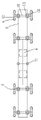
FIG. 4 is a schematic top view of the support system of the large cantilever capping beam for soft foundation in the present invention;
fig. 5 is a schematic perspective view of a large cantilever capping beam prestress tension basket device in the first embodiment.
In the figure: the device comprises vertical support frames 1, longitudinal beams 2, steel pipe piles 3, piers 4, bearing platforms 5, traffic lanes 6, the ground 7, a large cantilever capping beam vertical projection 8, steel pipes 9, pile steel longitudinal beams 23, lower steel cross beams 10, vertical steel support columns 11, subsections 12, flanges 13, upper steel cross beams 14, support assemblies 15, auxiliary support columns 16, jacks 17, upper steel plates 18, inclined supports 19, lower steel plates 20, steel rib plates 21, distribution beams 22, large cantilever capping beam templates 24, slope-adjusting steel pipes 25, railings 26, construction channels 27, bamboo rubber plates 28, a carrying platform 30, suspension rods 31, connecting rods 32, guardrails 33, transverse protection rods 34, material inlet windows 35, lower bolts 36, upper bolts 37, longitudinal rods 38, cross rods 39, longitudinal cable penetrating pipes 47 and large cantilever capping beams 48.
Detailed Description
The invention is further described with reference to the following detailed description and accompanying drawings.
First embodiment, referring to fig. 1 to 5, a construction method of a large cantilever capping beam of a soft foundation, which is implemented by using a support system of the large cantilever capping beam of the soft foundation and a large cantilever capping beam prestress tension hanging basket device as carriers.
The bracket system of the large cantilever bent cap of the soft foundation comprises a vertical support frame 1, two longitudinal beams 2 which are transversely distributed and a plurality of steel pipe piles 3 which are longitudinally distributed and positioned at two sides of a bearing platform of the pier. Two steel pipe piles are provided on the side of the pier 4 facing the cap 5. Two piers are arranged on the bearing platform. And a traffic lane 6 is arranged between two adjacent steel pipe piles positioned on the same side of the pier. The steel-pipe pile is including inserting two pairs of steel pipes 9 in the cantilever bent cap both sides along transverse distribution that just is located big cantilever bent cap vertical projection 8 outsidely in ground 7, and two steel pipes in same pair of steel pipe are connected together along transverse distribution and through pile portion steel longeron 23, and the pile portion steel longeron on two pairs of steel pipes links together through lower steel crossbeam 10, is equipped with a perpendicular support frame 1 on the lower steel crossbeam. And the vertical support frame supported on the bearing platform is arranged between the two piers.
The vertical support frame comprises two vertical steel support columns 11 which are transversely distributed. The vertical steel support column comprises a plurality of sections 12, and adjacent sections are connected together through flanges 13. The upper ends of the two vertical steel support columns are connected together through an upper steel cross beam 14. Two transversely distributed support assemblies 15 are arranged on the upper steel beam. The support assembly includes auxiliary support columns 16, jacks 17 and upper steel plates 18. The auxiliary support columns 16 and jacks 17 are attached to the upper steel beam (where the jacks rest directly on the upper steel beam). The upper steel plate is positioned right above the auxiliary supporting column 16 and the jack 17. The upper support assembly is connected with the longitudinal beam through an upper steel plate. The two support assemblies support the two longitudinal beams in a one-to-one correspondence. The two longitudinal beams are connected together through a plurality of longitudinally distributed connecting steel bars. All the support supports support the longitudinal beam. The vertical steel support columns of the vertical support frames which are positioned at two sides of the bearing platform and are adjacent to the bearing platform are connected together through inclined supports 19. And the vertical steel support column of the vertical support frame positioned on the bearing platform is also connected with the vertical support steel column of the adjacent vertical support frame through an inclined support. The lower ends of the vertical steel support columns are supported on the lower steel cross beam through lower steel plates 20. The lower steel plate is connected with the lower steel beam through two steel rib plates 21 which are convenient to be arranged at two sides of the lower steel beam. A plurality of distribution beams 22 are arranged on the two longitudinal beams. The distributing beam is provided with a slope-adjusting steel pipe 25 for supporting the large cantilever capping beam template 24. A balustrade 26 is also provided on the distribution beam. A construction channel 27 is arranged between the railing and the large cantilever capping beam template. The ground of the construction channel is paved with a bamboo plywood 28.
The large cantilever bent cap prestress tensioning hanging basket device comprises a carrying platform 30, a hanging frame with the lower end connected to the carrying platform and a hooking frame connected to the upper end of the hanging frame. The loading platform and the suspension bracket are positioned on the same side of the suspension bracket. The hanger comprises at least 4 hanger rods 31. Four suspension rods are distributed on two transverse sides of the carrying platform in pairs, and 2 suspension rods positioned on the same transverse side of the carrying platform are longitudinally distributed and connected together through a plurality of connecting rods 32 distributed in the vertical direction. The connecting rod extends in the longitudinal direction. Connecting rod and 2 suspension rod connection at the connecting rod both ends constitute the cat ladder, and the cat ladder has two and distributes in cargo platform's horizontal both sides in this embodiment. Guard rails 33 are arranged on the front, the rear, the left and the right of the carrying platform. Two suspension rods which are positioned outside the loading platform and distributed on the two transverse sides of the loading platform are connected together through a plurality of transverse protective rods 34 distributed along the vertical direction. The transverse protection rod and 2 vertical suspension rods connected to two ends of the transverse protection rod form the guardrail positioned outside the loading platform. Two of the suspension rods, the transverse protection rod and the hooking frame which are positioned at the top are positioned outside the loading platform and distributed at the two transverse sides of the loading platform to form a material inlet window 35. The suspension bracket is connected with the object carrying platform and the hook bracket only through the suspension rod. The suspension bar is detachably connected to the carrier platform by means of a lower bolt 36. The hanger bar and the hooking bracket are detachably connected together by an upper bolt 37. The hooking frame comprises two longitudinal bars 38 and a plurality of transverse bars 39 distributed longitudinally and connecting the two longitudinal bars together.
The concrete construction process of the large cantilever bent cap of the device comprises the following steps: step one, steel pipe pile installation: the steel pipe piles comprise two pairs of steel pipes which are inserted into the ground and positioned outside the vertical projection of the large cantilever capping beam and are distributed on two sides of the large cantilever capping beam along the transverse direction, two steel pipes in the same pair of steel pipes are distributed along the transverse direction and are connected together through pile steel longitudinal beams, and the pile steel longitudinal beams on the two pairs of steel pipes are connected together through lower steel cross beams; step two, mounting a vertical support frame: a vertical support frame is installed on each steel pipe pile, the vertical support frame comprises two vertical steel support columns which are transversely distributed, the upper ends of the two vertical steel support columns are connected together through an upper steel cross beam, two support assemblies which are transversely distributed are arranged on the upper steel cross beam, each support assembly comprises an auxiliary support column and a jack, and the lower ends of the vertical steel support columns are supported on the lower steel cross beam; thirdly, building a construction platform and installing a template: supporting two longitudinal beams on jacks of two support assemblies in all the vertical support frames in a one-to-one corresponding mode, wherein the jacks are in an extending state, the longitudinal beams and the auxiliary support columns are spaced at intervals, the two longitudinal beams are connected together through a plurality of reinforcing steel bars distributed along the longitudinal direction, a plurality of distribution beams are arranged on the two longitudinal beams, railings and slope adjusting steel pipes are arranged on the distribution beams, a large cantilever capping beam template is built by taking the slope adjusting steel pipes and the distribution beams as supports, and a steel bar framework and a plurality of longitudinal cable penetrating pipes 47 with two ends connected with the large cantilever capping beam template in a sealing mode are arranged in a cavity formed by the large cantilever capping beam template; fourthly, pouring: pouring concrete into the cavity, wherein the concrete and the steel reinforcement framework form a large cantilever capping beam 48 supported on the pier; fifthly, tensioning the large cantilever bent cap for the first time: when the strength of the concrete is greater than 90% of a design value and the age is more than 15 days, penetrating a steel strand into the longitudinal cable penetrating pipe, pulling the steel strand by taking the construction platform as an operation platform until the strength of pulling the steel strand is 65-75 of the design strength of the steel strand, connecting clamping blocks which are abutted against two end faces of the large cantilever capping beam at two ends of the steel strand, and loosening the tensioning effect on the steel strand; sixthly, dismantling: loosening the jack to enable the longitudinal beam to sink and support on the auxiliary supporting column, removing the construction platform, the vertical supporting frame and the steel pipe pile, and directly pulling out the steel pipe from the ground; seventhly, mounting the bridge plate on the large cantilever bent cap; eighthly, tensioning the large cantilever cover beam for the second time: and pulling the steel strand by taking a hanging basket hung on the bridge plate as an operation platform, wherein the strength from the steel strand to the steel strand pulling is equal to the design strength of the steel strand, and then the two ends of the steel strand are connected with clamping blocks which are butted on the two end surfaces of the large cantilever bent cap, so that the tensioning effect on the steel strand is released.
The second embodiment is different from the first embodiment in that:
the steel pipe external thread is connected with the overcoat that the degradable plastics was made and is formed, thereby makes the steel pipe deviate from in the overcoat through rotatory mode in the fifth step and realize removing in the steel pipe follow ground.
Claims (2)
1. The construction method of the large cantilever bent cap of the soft foundation is characterized by comprising the following steps of: the steel pipe piles comprise two pairs of steel pipes which are inserted into the ground and positioned outside the vertical projection of the large cantilever capping beam and are distributed on two sides of the large cantilever capping beam along the transverse direction, two steel pipes in the same pair of steel pipes are distributed along the transverse direction and are connected together through pile steel longitudinal beams, and the pile steel longitudinal beams on the two pairs of steel pipes are connected together through lower steel cross beams; step two, mounting a vertical support frame: a vertical support frame is installed on each steel pipe pile, the vertical support frame comprises two vertical steel support columns which are transversely distributed, the upper ends of the two vertical steel support columns are connected together through an upper steel cross beam, two support assemblies which are transversely distributed are arranged on the upper steel cross beam, each support assembly comprises an auxiliary support column and a jack, and the lower ends of the vertical steel support columns are supported on the lower steel cross beam; thirdly, building a construction platform and installing a template: two longitudinal steel beams are supported on jacks of two support assemblies in all the vertical support frames in a one-to-one correspondence mode, the jacks are in an extending state, the longitudinal beams and the auxiliary support columns are spaced at intervals, the two longitudinal beams are connected together through a plurality of reinforcing steel bars distributed in the longitudinal direction, a plurality of distribution beams are arranged on the two longitudinal beams, railings and slope adjusting steel pipes are arranged on the distribution beams, a large cantilever capping beam template is built by taking the slope adjusting steel pipes and the distribution beams as supports, and a steel bar framework and a plurality of longitudinal cable penetrating pipes with two ends connected with the large cantilever capping beam template in a sealing mode are arranged in a cavity formed by the large cantilever capping beam template; fourthly, pouring: pouring concrete into the cavity, wherein the concrete and the steel reinforcement framework form a large cantilever capping beam supported on a pier; fifthly, tensioning the large cantilever bent cap for the first time: when the strength of the concrete is greater than 90% of a design value and the age is more than 15 days, penetrating a steel strand into the longitudinal cable penetrating pipe, pulling the steel strand by taking the construction platform as an operation platform until the strength of pulling the steel strand is 65-75 of the design strength of the steel strand, connecting clamping blocks which are abutted against two end faces of the large cantilever capping beam at two ends of the steel strand, and loosening the tensioning effect on the steel strand; sixthly, dismantling: loosening the jack to enable the longitudinal beam to sink and be supported on the auxiliary supporting column, and removing the construction platform, the vertical supporting frame and the steel pipe pile; seventhly, mounting the bridge plate on the large cantilever bent cap; eighthly, tensioning the large cantilever cover beam for the second time: and pulling the steel strand by taking a hanging basket hung on the bridge plate as an operation platform, wherein the strength from the steel strand to the steel strand pulling is equal to the design strength of the steel strand, and then the two ends of the steel strand are connected with clamping blocks which are butted on the two end surfaces of the large cantilever bent cap, so that the tensioning effect on the steel strand is released.
2. The construction method of the soft foundation large cantilever bent cap according to claim 1, wherein the steel pipe is externally threaded with an outer sleeve made of degradable plastics, and in the fifth step, the steel pipe is removed from the ground by being taken out from the outer sleeve in a rotating manner.
Priority Applications (1)
| Application Number | Priority Date | Filing Date | Title |
|---|---|---|---|
| CN202010524005.XA CN111622124B (en) | 2020-06-10 | 2020-06-10 | Construction method and support system for large cantilever bent cap of soft foundation |
Applications Claiming Priority (1)
| Application Number | Priority Date | Filing Date | Title |
|---|---|---|---|
| CN202010524005.XA CN111622124B (en) | 2020-06-10 | 2020-06-10 | Construction method and support system for large cantilever bent cap of soft foundation |
Publications (2)
| Publication Number | Publication Date |
|---|---|
| CN111622124A CN111622124A (en) | 2020-09-04 |
| CN111622124B true CN111622124B (en) | 2021-07-27 |
Family
ID=72258409
Family Applications (1)
| Application Number | Title | Priority Date | Filing Date |
|---|---|---|---|
| CN202010524005.XA Active CN111622124B (en) | 2020-06-10 | 2020-06-10 | Construction method and support system for large cantilever bent cap of soft foundation |
Country Status (1)
| Country | Link |
|---|---|
| CN (1) | CN111622124B (en) |
Families Citing this family (1)
| Publication number | Priority date | Publication date | Assignee | Title |
|---|---|---|---|---|
| CN113089491A (en) * | 2021-04-09 | 2021-07-09 | 中铁九局集团第七工程有限公司 | Construction method of large cantilever prestressed concrete bent cap |
Family Cites Families (7)
| Publication number | Priority date | Publication date | Assignee | Title |
|---|---|---|---|---|
| KR101511265B1 (en) * | 2013-08-20 | 2015-04-10 | 서울특별시 | Construction method for supporting structure of temporary bridge tayp |
| JP6872993B2 (en) * | 2017-06-30 | 2021-05-19 | 鹿島建設株式会社 | Pile foundation structure |
| CN209039993U (en) * | 2018-07-27 | 2019-06-28 | 中国建筑第六工程局有限公司 | A kind of device carrying out the tensioning of great cantilever bent cap using movable supporting frame |
| CN209025103U (en) * | 2018-11-01 | 2019-06-25 | 重庆市勘测院 | For building the pile-column foundation structure of escape truck or emergency bridge |
| CN109338896B (en) * | 2018-11-28 | 2020-12-01 | 中国铁建大桥工程局集团有限公司 | Construction method of broad-width concrete PK box girder support system |
| CN210134362U (en) * | 2019-03-28 | 2020-03-10 | 中交路桥建设有限公司 | Bridge overlength cantilever bent cap construction support |
| CN110820561A (en) * | 2019-09-17 | 2020-02-21 | 浙江大学城市学院 | Large cantilever prestress bent cap support device and construction method |
-
2020
- 2020-06-10 CN CN202010524005.XA patent/CN111622124B/en active Active
Also Published As
| Publication number | Publication date |
|---|---|
| CN111622124A (en) | 2020-09-04 |
Similar Documents
| Publication | Publication Date | Title |
|---|---|---|
| CN103635643B (en) | The construction method of nigh-level synthesis steel bar concrete cylindrical shell | |
| CN112411391A (en) | Single-column capping beam steel pipe column Bailey beam construction supporting system and construction method thereof | |
| CN110593114A (en) | Box girder construction method based on large-span box girder multi-hoop truss support bailey bracket | |
| CN112267369A (en) | Non-span upright post steel trestle structure, pushing installation device and construction method | |
| CN111622124B (en) | Construction method and support system for large cantilever bent cap of soft foundation | |
| CN210049103U (en) | High-grade high-speed highway bracket spanned by large-span cast-in-place box girder | |
| CN205242278U (en) | A triangle string basket method is hanged and is watered device for deck bridge construction | |
| JP3737475B2 (en) | Box girder bridge structure and construction method | |
| CN112726411A (en) | Integral dragging construction method for single-hole large cantilever steel truss girder | |
| CN109778700B (en) | Cast-in-place trough beam three-point sliding pushing construction method for crossing existing road | |
| CN203307733U (en) | Construction platform system of concrete pier of viaduct | |
| CN212956140U (en) | Support system device of large cantilever bent cap of soft foundation | |
| CN111794074B (en) | Arch bridge concrete beam and beam forming method thereof | |
| CN110184915B (en) | Cast-in-situ tower column of cable-stayed bridge and construction method thereof | |
| CN211815605U (en) | Construction device for pile column type pier tie beam and capping beam | |
| CN210766867U (en) | A template system for retaining wall | |
| KR102296982B1 (en) | Transfer Structure Construction Method Using U-shaped Steel Girder | |
| CN113338537A (en) | Construction method of ultrahigh large-section concrete frame column | |
| CN212925792U (en) | Large cantilever bent cap prestress tensioning hanging basket device | |
| CN111395850A (en) | Assembled tower frame for cable hoisting system and erection method | |
| CN109208609B (en) | Assembled double-point fixed foundation pit pavement structure and construction method thereof | |
| CN210657999U (en) | Cast-in-situ tower column of cable-stayed bridge | |
| CN215164738U (en) | Tied-rod arch type fast-splicing support | |
| CN211848952U (en) | Steel constructs bridge support | |
| CN214656277U (en) | Non-span middle upright column steel trestle structure |
Legal Events
| Date | Code | Title | Description |
|---|---|---|---|
| PB01 | Publication | ||
| PB01 | Publication | ||
| SE01 | Entry into force of request for substantive examination | ||
| SE01 | Entry into force of request for substantive examination | ||
| GR01 | Patent grant | ||
| GR01 | Patent grant |