CN111618179A - A low-voltage electrical arc-striking plate and double-gold in-mold automatic punching and welding system - Google Patents

A low-voltage electrical arc-striking plate and double-gold in-mold automatic punching and welding system Download PDF

Info

Publication number
CN111618179A
CN111618179A CN202010507916.1A CN202010507916A CN111618179A CN 111618179 A CN111618179 A CN 111618179A CN 202010507916 A CN202010507916 A CN 202010507916A CN 111618179 A CN111618179 A CN 111618179A
Authority
CN
China
Prior art keywords
plate
double
gold
die
edge
Prior art date
Legal status (The legal status is an assumption and is not a legal conclusion. Google has not performed a legal analysis and makes no representation as to the accuracy of the status listed.)
Granted
Application number
CN202010507916.1A
Other languages
Chinese (zh)
Other versions
CN111618179B (en
Inventor
不公告发明人
Current Assignee (The listed assignees may be inaccurate. Google has not performed a legal analysis and makes no representation or warranty as to the accuracy of the list.)
Beijing Panzhi Electric Co ltd
Original Assignee
Yueqing Yedao Electromechanical Co ltd
Priority date (The priority date is an assumption and is not a legal conclusion. Google has not performed a legal analysis and makes no representation as to the accuracy of the date listed.)
Filing date
Publication date
Application filed by Yueqing Yedao Electromechanical Co ltd filed Critical Yueqing Yedao Electromechanical Co ltd
Priority to CN202010507916.1A priority Critical patent/CN111618179B/en
Publication of CN111618179A publication Critical patent/CN111618179A/en
Application granted granted Critical
Publication of CN111618179B publication Critical patent/CN111618179B/en
Active legal-status Critical Current
Anticipated expiration legal-status Critical

Links

Images

Classifications

    • B—PERFORMING OPERATIONS; TRANSPORTING
    • B21—MECHANICAL METAL-WORKING WITHOUT ESSENTIALLY REMOVING MATERIAL; PUNCHING METAL
    • B21D—WORKING OR PROCESSING OF SHEET METAL OR METAL TUBES, RODS OR PROFILES WITHOUT ESSENTIALLY REMOVING MATERIAL; PUNCHING METAL
    • B21D37/00—Tools as parts of machines covered by this subclass
    • B21D37/08—Dies with different parts for several steps in a process
    • B—PERFORMING OPERATIONS; TRANSPORTING
    • B21—MECHANICAL METAL-WORKING WITHOUT ESSENTIALLY REMOVING MATERIAL; PUNCHING METAL
    • B21D—WORKING OR PROCESSING OF SHEET METAL OR METAL TUBES, RODS OR PROFILES WITHOUT ESSENTIALLY REMOVING MATERIAL; PUNCHING METAL
    • B21D28/00—Shaping by press-cutting; Perforating
    • B21D28/02—Punching blanks or articles with or without obtaining scrap; Notching
    • B21D28/14—Dies
    • B—PERFORMING OPERATIONS; TRANSPORTING
    • B21—MECHANICAL METAL-WORKING WITHOUT ESSENTIALLY REMOVING MATERIAL; PUNCHING METAL
    • B21D—WORKING OR PROCESSING OF SHEET METAL OR METAL TUBES, RODS OR PROFILES WITHOUT ESSENTIALLY REMOVING MATERIAL; PUNCHING METAL
    • B21D28/00—Shaping by press-cutting; Perforating
    • B21D28/24—Perforating, i.e. punching holes
    • B21D28/34—Perforating tools; Die holders
    • B—PERFORMING OPERATIONS; TRANSPORTING
    • B21—MECHANICAL METAL-WORKING WITHOUT ESSENTIALLY REMOVING MATERIAL; PUNCHING METAL
    • B21D—WORKING OR PROCESSING OF SHEET METAL OR METAL TUBES, RODS OR PROFILES WITHOUT ESSENTIALLY REMOVING MATERIAL; PUNCHING METAL
    • B21D35/00—Combined processes according to or processes combined with methods covered by groups B21D1/00 - B21D31/00
    • B21D35/001—Shaping combined with punching, e.g. stamping and perforating
    • B—PERFORMING OPERATIONS; TRANSPORTING
    • B21—MECHANICAL METAL-WORKING WITHOUT ESSENTIALLY REMOVING MATERIAL; PUNCHING METAL
    • B21D—WORKING OR PROCESSING OF SHEET METAL OR METAL TUBES, RODS OR PROFILES WITHOUT ESSENTIALLY REMOVING MATERIAL; PUNCHING METAL
    • B21D35/00—Combined processes according to or processes combined with methods covered by groups B21D1/00 - B21D31/00
    • B21D35/002—Processes combined with methods covered by groups B21D1/00 - B21D31/00
    • B—PERFORMING OPERATIONS; TRANSPORTING
    • B23—MACHINE TOOLS; METAL-WORKING NOT OTHERWISE PROVIDED FOR
    • B23P—METAL-WORKING NOT OTHERWISE PROVIDED FOR; COMBINED OPERATIONS; UNIVERSAL MACHINE TOOLS
    • B23P23/00—Machines or arrangements of machines for performing specified combinations of different metal-working operations not covered by a single other subclass
    • B23P23/04—Machines or arrangements of machines for performing specified combinations of different metal-working operations not covered by a single other subclass for both machining and other metal-working operations

Landscapes

  • Engineering & Computer Science (AREA)
  • Mechanical Engineering (AREA)
  • Physics & Mathematics (AREA)
  • Optics & Photonics (AREA)
  • Punching Or Piercing (AREA)

Abstract

本发明公开了一种低压电器引弧板与双金模内自动冲焊系统,包括主台架和副台架,在主台架上设置有冲焊模具,在副台架上设置有引弧板送料组件和双金送料组件;在冲焊模具出口端设置有配套的水平焊接组件及竖立焊接组件;水平焊接组件下方设置有双金冲裁机构及双金顶升组件。本发明的自动冲焊系统,在同一冲焊模具内,完成引弧板的冲孔、切边、落料、一次折弯、二次折弯,完成双金的切边、落料、送料,完成引弧板与双金在冲焊模具内的一次组装、引弧板与双金一出二的模内自动化冲焊、及不合格双金的自动分拣。

Figure 202010507916

The invention discloses an automatic punching and welding system in a low-voltage electrical arc striking plate and a double-gold mold. Plate feeding assembly and double-gold feeding assembly; matching horizontal welding assembly and vertical welding assembly are arranged at the outlet end of the punching and welding die; double-gold punching mechanism and double-gold lifting assembly are arranged below the horizontal welding assembly. The automatic punching and welding system of the present invention completes the punching, trimming, blanking, primary bending and secondary bending of the arc striking plate in the same punching and welding die, and completes the trimming, blanking and feeding of the double metal. Complete the one-time assembly of the arc ignition plate and the double metal in the stamping and welding mold, the automatic punching and welding of the arc ignition plate and the double metal in the die, and the automatic sorting of the unqualified double metal.

Figure 202010507916

Description

一种低压电器引弧板与双金模内自动冲焊系统A low-voltage electrical arc-striking plate and double-gold in-mold automatic punching and welding system

技术领域technical field

本发明属于机械设备技术领域,涉及一种低压电器引弧板与双金模内自动冲焊系统。The invention belongs to the technical field of mechanical equipment, and relates to an automatic punching and welding system in a low-voltage electrical arc striking plate and a double-gold mold.

背景技术Background technique

引弧板与双金组装件是低压电器的核心部件,目前引弧板与双金组装件的加工基本上采用冲压、组装、焊接分离操作,通过不同的冲压模具将引弧板与双金冲压成型后,再通过人工将其叠放成码垛,由人工组装放置在焊接设备的夹具内,再由专用焊接设备实现焊接成型。The arc-striking plate and the double-metal assembly are the core components of low-voltage electrical appliances. At present, the arc-striking plate and the double-metal assembly are basically processed by stamping, assembling, and welding separation operations. After forming, they are manually stacked into pallets, manually assembled and placed in the fixture of the welding equipment, and then welded and formed by special welding equipment.

这个过程使得引弧板与双金组装件对断路器的性能产生不一致,不能返修的占65%-85%。另外,引弧板由于是多折弯,无法实现顺畅不卡料的自动送料,自动化操作难以实现;引弧板和双金是不同复合金属,焊接时容易产生飞溅,飞溅导致焊接的连接牢固度不合格,而且飞溅一旦粘结在模具上,会导致模具被损害而无法产出合格产品;冲压效率高、焊接效率低、冲压效率造成浪费、焊接电极过热造成电极寿命短,导致现有技术无法在模内实现冲压与焊接,即浪费劳动力,产品报废高,工艺工序繁琐,降低了效率,同时增加了模具、人力、管理成本,无法满足批量生产的需求。This process makes the arc ignition plate and the double-gold assembly inconsistent in the performance of the circuit breaker, and 65%-85% of them cannot be repaired. In addition, due to the multi-bending of the arc pilot plate, it is impossible to achieve smooth automatic feeding without jamming, and automatic operation is difficult to achieve; the arc pilot plate and the double metal are different composite metals, which are prone to splash during welding, and the splash causes the welding connection firmness. Unqualified, and once the splash adheres to the mold, the mold will be damaged and the qualified product cannot be produced; the stamping efficiency is high, the welding efficiency is low, the stamping efficiency is wasteful, and the welding electrode is overheated and the electrode life is short, which makes the existing technology impossible. The realization of stamping and welding in the mold is a waste of labor, high product scrap, cumbersome process, reducing efficiency, and at the same time increasing mold, labor, and management costs, which cannot meet the needs of mass production.

经检索,目前还未有在同一工位模具内实现连续冲压的全自动焊接系统,还没有针对低压电器引弧板与双金的模内自动冲焊设备的应用。After searching, there is no automatic welding system that realizes continuous stamping in the same station mold, and there is no application of automatic in-mold stamping and welding equipment for low-voltage electrical arc-striking plates and double metal.

发明内容SUMMARY OF THE INVENTION

本发明的目的是提供一种低压电器引弧板与双金模内自动冲焊系统,解决了现有技术在引弧板与双金冲压与焊接过程中,采用人工分步操作,引弧板与双金不能在模内实现全自动送料、冲压、焊接、裁剪成型,导致焊接不良、产品质量低、生产成本高、工作效率不高的问题。The purpose of the present invention is to provide a low-voltage electrical arc striking plate and an automatic punching and welding system in the double-gold mold, which solves the problem of using manual step-by-step operations in the process of punching and welding the arc striking plate and the double-gold metal in the prior art. With Shuangjin, automatic feeding, stamping, welding, cutting and forming cannot be realized in the mold, resulting in poor welding, low product quality, high production cost, and low work efficiency.

本发明所采用的技术方案是,一种低压电器引弧板与双金模内自动冲焊系统,包括主台架和副台架,在主台架上设置有冲焊模具,在副台架上设置有引弧板送料组件和双金送料组件;在冲焊模具出口端设置有配套的水平焊接组件及竖立焊接组件;水平焊接组件下方设置有双金冲裁机构及双金顶升组件。The technical scheme adopted in the present invention is, an automatic punching and welding system in a low-voltage electrical arc striking plate and a double-gold mold, including a main frame and a sub-frame, the main frame is provided with a punching and welding die, and the sub-frame is provided with a punching and welding die. The arc-striking plate feeding assembly and the double-gold feeding assembly are arranged on the upper part; the matching horizontal welding assembly and the vertical welding assembly are arranged at the outlet end of the punching and welding die; the double-gold punching mechanism and the double-gold lifting assembly are arranged below the horizontal welding assembly.

本发明的低压电器引弧板与双金模内自动冲焊系统,其特征还在于:The automatic punching and welding system in the low-voltage electrical arc striking plate and the double-gold mold of the present invention is further characterized in that:

所述的冲焊模具的结构是,包括下模座和上模座,下模座通过下垫脚与主台架下部的基座固定连接,上模座通过上垫脚与主台架上部固定连接;下模座上表面安装有下模垫板,下模垫板上表面安装有下模板,下模板向上间隔设置有上脱料板,上脱料板与上模板间隔连接,上模板向上与上模垫板及上模座固定为一体,上模座靠近中间位置设有模柄;下模座与上模座之间滑动套接;上模板下表面设置有两对弹弓膠,上脱料板上表面设置有一对压料压条,该对压料压条与水平焊接组件的投影线垂直,该对压料压条之间开有一段通槽称为压料槽。The structure of the punching and welding die includes a lower die base and an upper die base, the lower die base is fixedly connected to the base of the lower part of the main frame through the lower foot, and the upper mould base is fixedly connected to the upper part of the main frame through the upper foot; A lower die pad is installed on the upper surface of the lower die base, a lower die plate is installed on the upper surface of the lower die pad, an upper stripper plate is arranged at an upward interval of the lower die plate, the upper stripper plate is connected with the upper die plate at intervals, and the upper die plate is upwardly connected to the upper die. The backing plate and the upper die base are fixed as a whole, and the upper die base is provided with a die handle near the middle position; the lower die base and the upper die base are slidably connected; two pairs of slingshot glue are arranged on the lower surface of the upper die plate, and the upper stripper The surface is provided with a pair of pressing strips, the pair of pressing strips is perpendicular to the projection line of the horizontal welding assembly, and there is a section of through groove between the pair of pressing strips, which is called the pressing groove.

所述的所述的冲焊模具内部的引弧板排样区间分为上模部分和下模部分,具体布置方式是,The described arc striking plate layout area inside the punching and welding die is divided into an upper die part and a lower die part, and the specific arrangement is as follows:

上模部分从输入端到输出端依次间隔设置有一对冲孔针、上模镶件一、上模镶件二、上模一次折弯、上模二次折弯、上模镶件三;The upper die part is provided with a pair of punching pins, a first upper die insert, a second upper die insert, a first bending of the upper die, a second bending of the upper die, and a third upper die insert at intervals from the input end to the output end;

下模部分均固定安装在下模垫板的上表面,从输入端到输出端依次间隔设置有一对冲孔镶件、下模镶件一、下模镶件二、下模一次折弯、下模二次折弯、下模镶件三以及多对浮钉。The lower die parts are fixedly installed on the upper surface of the lower die backing plate. From the input end to the output end, a pair of punching inserts, lower die inserts 1, lower die inserts 2, lower die primary bending, lower die 2 are arranged at intervals. Secondary bending, three lower die inserts and multiple pairs of floating nails.

所述的竖立焊接组件的结构是,包括上垫板,上垫板向上通过上模板的四方缺口与上模垫板固定连接;在上垫板下表面连接有上端板,上端板下表面安装有双滑杆汽缸的缸体,双滑杆汽缸的双滑杆端头固定有下端板,下端板下表面并排间隔设置一对校正块;每个校正块前端中间开有矩形槽,矩形槽的前部镶有凸电极,在矩形槽的后部设置有冷冻液槽,校正块下端设置有凸尖,凸尖前后斜面分别设有前台阶和后台阶。The structure of the vertical welding assembly includes an upper backing plate, and the upper backing plate is fixedly connected to the upper die backing plate upward through the square gap of the upper template; an upper end plate is connected on the lower surface of the upper backing plate, and a lower surface of the upper end plate is installed The cylinder block of the double sliding rod cylinder, the double sliding rod end of the double sliding rod cylinder is fixed with a lower end plate, and a pair of correction blocks are arranged side by side on the lower surface of the lower end plate; A convex electrode is inlaid on the part, a freezing liquid tank is arranged at the rear of the rectangular groove, a convex tip is arranged at the lower end of the correction block, and a front step and a rear step are respectively arranged on the front and rear slopes of the convex tip.

本发明的有益效果是,在同一冲焊模具内,完成引弧板的冲孔、切边、落料、一次折弯、二次折弯,完成双金的切边、落料、送料,完成引弧板与双金的模内一次组装、引弧板与双金一出二的模内自动化冲焊、及不合格双金的自动分拣。装置整体的设备成本降低30%,生产效率提高10倍,电极寿命增长50倍,焊接强度达100%,合格率达到100%。The beneficial effect of the present invention is that in the same punching and welding die, the punching, edge trimming, blanking, primary bending and secondary bending of the arc striking plate are completed, and the edge trimming, blanking and feeding of the double metal are completed. One-time assembly in the mold of the arc ignition plate and the double gold, automatic in-mold punching and welding of the arc ignition plate and the double gold, and automatic sorting of the unqualified double gold. The overall equipment cost of the device is reduced by 30%, the production efficiency is increased by 10 times, the electrode life is increased by 50 times, the welding strength is 100%, and the qualification rate is 100%.

附图说明Description of drawings

图1是本发明系统的整体结构示意图;Fig. 1 is the overall structure schematic diagram of the system of the present invention;

图2是本发明工作对象(引弧板与双金)的工位设置示意图;Fig. 2 is the work station arrangement schematic diagram of the present invention's work object (arc striking plate and double gold);

图3是本发明中的冲焊模具2的结构示意图;Fig. 3 is the structural representation of punching welding die 2 in the present invention;

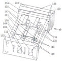
图4是本发明中的竖立焊接组件89的结构示意图;FIG. 4 is a schematic structural diagram of the vertical welding assembly 89 in the present invention;

图5a是本发明中的双金冲裁机构6结构示意图;5a is a schematic structural diagram of the double-gold blanking mechanism 6 in the present invention;

图5b是图5a中的e向视图;Fig. 5b is the e-direction view in Fig. 5a;

图5c是图5b中的d向爆炸示图;Fig. 5c is a d-direction exploded view in Fig. 5b;

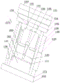
图6是本发明冲焊模具2内部引弧板排样区间36的配置分布示意图;6 is a schematic diagram of the configuration and distribution of the layout section 36 of the arc striking plate inside the punching and welding die 2 of the present invention;

图7是本发明冲焊模具2内部上模部分与下模部分的透视结构示意图;Fig. 7 is the perspective structure schematic diagram of the inner upper die part and the lower die part of the punching and welding die 2 of the present invention;

图8是本发明冲焊模具2及配置设备的结构示意图;Fig. 8 is the structural representation of the punching and welding die 2 of the present invention and the configuration equipment;

图9是本发明中的双金机械手88的结构示意图。FIG. 9 is a schematic structural diagram of the double-gold manipulator 88 in the present invention.

图中,1.主台架,2.冲焊模具,3.引弧板送料组件,4.双金送料组件,5.水平焊接组件,6.双金冲裁机构,7.双金顶升组件,8.副台架,9.引弧板料带,10.第一工位,11.圆冲孔,12.第三工位,13.第四工位,14.第五工位,15.双金料带,16.第六工位,17.双金,18.第七工位,19.引弧板,20.第一辅助工位,21.第二工位,22.模柄,23.上模座,24.上模垫板,25.上模板,26.压料压条,27.上脱料板,28.下模座,29.下模垫板,30.下模板,31.输送孔,32.焊接面,33.双金输送通道,34.光轴,35.导套,36.引弧板排样区间,37.双金通道出口,38.切缝,39.焊接点,40.第八工位,41.推动杆,42.双金储存槽,43.冲孔针,44.浮钉,45.卡口滑槽,46.弹簧,47.推杆,48.冲孔镶件,49.上模镶件一,50.下模镶件一,51.T型刀口六,52.T型块一,53.T型刀口一,54.T型刀口二,55.上模镶件二,56.T型块二,57.下模镶件二,58.上模一次折弯,59.斜边刃一,60.直边刃一,61.直边刃二,62.下模一次折弯,63.斜边刃二,64.上模二次折弯,65.直边刃六,66.V边刃,67.直边刃三,68.斜边刃三,69.下模二次折弯,70.直边刃四,71.T型块八,72.上模镶件三,73.T型刀口五,74.T型块五,75.下模镶件三,76.箭头一,77.箭头二,78.一次折弯输出槽,79.一次折弯槽,80.二次折弯槽,81.二次折弯输出槽,82.冲裁槽,83.定位槽,84.成品收集槽,85.废品收集槽,86.第二辅助工位,87.引弧板机械手,88.双金机械手,89.竖立焊接组件,90.冲孔槽,91.下板,92.托板,93.导向棒,94.上推气缸,95.电极,96.滑动架,97.直线滑动副,98.气缸杆,99.立板,100.悬挂板,101.气缸一,102.气缸二,103.F型滑座,104.推板一,105.活性接头,106.连接板,107.竖立F型滑板,108.挡板,109.气缸三,110.滑块,111.活性连接座,112.推板二,113.台阶插销,114.U型口,115.双滚轮一,116.双滚轮二,117.导向输送板,118.单滚轮一,119.单滚轮二,120.槽板,121.上垫板,122.上端板,123.双滑杆汽缸,124.双滑杆,125.下端板,126.校正块,127.凸尖,128.前台阶,129.凸电极,130.后台阶,131.冷冻液槽,132.矩形槽,133.液压缸一,134.固定板,135.滑动板,136.滑柱,137.推板三,138.滑动立板,139.细推杆,140.主切刀,141.销孔一,142.销孔二,143.滑套,144.台阶推杆,145.横切刀,146.定切刀,148.推板四,149.第一合格出料槽,150.液压缸二,151.第一次品出料槽,152.固定模座,153.横刀刃,154.弹弓膠,155.T型块三,156.斜角V型槽,157.直边刃五,158.第二合格出料槽,159.第二次品出料槽,160.分段线,161.让位槽,162.双金料带通道,163.光色幕,171.侧立面,172.四方槽,173.基座,174.插销一,175.插销二,176.弹簧孔,177.第一不合格冲裁单元,178.第一合格冲裁单元,179.第二不合格冲裁单元,180.第二合格冲裁单元。In the figure, 1. Main gantry, 2. Punching die, 3. Arc strike plate feeding assembly, 4. Double gold feeding assembly, 5. Horizontal welding assembly, 6. Double gold punching mechanism, 7. Double gold lifting Components, 8. Auxiliary stand, 9. Arc striking strip, 10. The first station, 11. Round punching, 12. The third station, 13. The fourth station, 14. The fifth station, 15. Double gold material belt, 16. Sixth station, 17. Double gold, 18. Seventh station, 19. Arc striking plate, 20. First auxiliary station, 21. Second station, 22. Die Shank, 23. Upper die seat, 24. Upper die pad, 25. Upper template, 26. Pressing bar, 27. Upper stripper, 28. Lower die seat, 29. Lower die pad, 30. Lower template , 31. Conveying hole, 32. Welding surface, 33. Double-gold conveying channel, 34. Optical axis, 35. Guide sleeve, 36. Arcing plate layout section, 37. Double-gold channel outlet, 38. Cutting slot, 39 .Welding point, 40. Eighth station, 41. Push rod, 42. Double gold storage slot, 43. Punching pin, 44. Floating pin, 45. Bayonet chute, 46. Spring, 47. Push rod, 48. Punching inserts, 49. Upper die insert 1, 50. Lower die insert 1, 51. T-shaped blade 6, 52. T-shaped block 1, 53. T-shaped blade 1, 54. T-shaped blade 2 , 55. Upper die insert 2, 56. T-block 2, 57. Lower die insert 2, 58. Upper die 1 bending, 59. Bevel edge 1, 60. Straight edge edge 1, 61. Straight edge Edge 2, 62. Lower die one time bending, 63. Bevel edge edge 2, 64. Upper die edge 2 bending, 65. Straight edge edge 6, 66. V edge edge, 67. Straight edge edge 3, 68. Oblique edge Edge 3, 69. Lower die secondary bending, 70. Straight edge 4, 71. T-block 8, 72. Upper die insert 3, 73. T-shaped blade 5, 74. T-block 5, 75 . Lower die insert 3, 76. Arrow 1, 77. Arrow 2, 78. Primary bending output groove, 79. Primary bending groove, 80. Secondary bending groove, 81. Secondary bending output groove, 82 . Blanking slot, 83. Positioning slot, 84. Finished product collection slot, 85. Waste collection slot, 86. Second auxiliary station, 87. Arc striker manipulator, 88. Double gold manipulator, 89. Vertical welding assembly, 90 .Punching groove, 91. Lower plate, 92. Support plate, 93. Guide rod, 94. Push-up cylinder, 95. Electrode, 96. Sliding frame, 97. Linear sliding pair, 98. Cylinder rod, 99. Vertical plate , 100. Suspension plate, 101. Cylinder one, 102. Cylinder two, 103. F-type sliding seat, 104. Push plate one, 105. Active joint, 106. Connecting plate, 107. Vertical F-type sliding plate, 108. Baffle plate , 109. Cylinder three, 110. Slider, 111. Active connection seat, 112. Push plate two, 113. Step bolt, 114. U-shaped mouth, 115. Double roller one, 116. Double roller two, 117. Guided conveying Plate, 118. Single Roller One, 119. Single Roller Two, 120. Groove Plate, 121. Upper Plate, 122. Upper End Plate, 123. Double Slide Bar Cylinder, 124. Double sliding rod, 125. Lower end plate, 126. Correction block, 127. Convex tip, 128. Front step, 129. Convex electrode, 130. Rear step, 131. Refrigerant tank, 132. Rectangular groove, 133 . Hydraulic cylinder 1, 134. Fixed plate, 135. Sliding plate, 136. Slide column, 137. Push plate 3, 138. Sliding vertical plate, 139. Thin push rod, 140. Main cutter, 141. Pin hole 1, 142. Pin hole II, 143. Sliding sleeve, 144. Step push rod, 145. Cross cutter, 146. Fixed cutter, 148. Push plate IV, 149. First qualified discharge chute, 150. Hydraulic cylinder II, 151. Discharging chute for the first product, 152. Fixed die base, 153. Cross blade, 154. Slingshot glue, 155. T-block three, 156. Bevel V-groove, 157. Straight edge five, 158. The second qualified discharge chute, 159. The second product discharge chute, 160. Segment line, 161. Give way, 162. Double gold material belt channel, 163. Light and color curtain, 171. Side elevation, 172 .Square groove, 173. Base, 174. Pin 1, 175. Pin 2, 176. Spring hole, 177. First unqualified punching unit, 178. First qualified punching unit, 179. Second unqualified punching unit Cutting unit, 180. Second qualified blanking unit.

具体实施方式Detailed ways

以下文字描述中的上、下、左、右位置均以各自对应附图的图上显示为准,实际安装位置以此类推。The upper, lower, left and right positions in the following text descriptions are all based on the figures shown in the corresponding drawings, and the actual installation positions are deduced by analogy.

参照图2、图6、图7、图8,本发明实施对象引弧板与双金冲焊组件实施的工艺流程是(该工艺流程是本发明创新点之一),2 , 6 , 7 and 8 , the process flow of the implementation object of the present invention is that the arc striking plate and the double-gold stamping welding assembly are implemented (this process flow is one of the innovations of the present invention),

X轴箭头方向为进料行进方向(另外在图8中,引弧板料带9沿箭头一76向前输送,双金料带15沿箭头二77向前输送,图2和图8的进料方向实质上是一致的),引弧板19随引弧板料带9沿多对卡口滑槽45呈水平姿态进料,双金17随双金料带15沿双金输送通道33呈竖直姿态进料,即引弧板料带9与双金料带15相互呈垂直角度同步输入冲焊模具2中;The direction of the X-axis arrow is the feeding direction (in addition, in Fig. 8, the arc-starting sheet material belt 9 is transported forward along the arrow one 76, the double-gold material belt 15 is transported forward along the arrow two 77, and Fig. 2 and Fig. 8 feed forward. The direction of the material is substantially the same), the arc-striking plate 19 is fed with the arc-striking plate material belt 9 along the multiple pairs of bayonet chutes 45 in a horizontal attitude, and the double-gold 17 follows the double-gold material belt 15 along the double-gold conveying channel 33. Feeding in a vertical attitude, that is, the arc-starting sheet material belt 9 and the double-gold material belt 15 are synchronously input into the punching and welding mold 2 at a vertical angle to each other;

第一路,沿引弧板19的行进方向依次设置有以下工位,第一工位10是加工引弧板料带9两边沿的圆冲孔11,第一工位10对应下模板30上的冲孔槽90(由冲孔镶件48向上与一对冲孔针43配合实施冲孔,引弧板料带9左边沿、右边沿同时冲孔,冲好的圆冲孔11作为引弧板机械手87向前牵拉引弧板料带9的插入孔);In the first way, the following workstations are arranged in sequence along the traveling direction of the arc striking plate 19 . The first workstation 10 is to process the circular punching holes 11 on both sides of the arc striking sheet strip 9 , and the first workstation 10 corresponds to the upper part of the lower template 30 . The punching groove 90 (the punching insert 48 is used to cooperate with a pair of punching needles 43 to perform punching, and the left and right edges of the arc-priming strip 9 are punched at the same time, and the punched circular punching hole 11 is used as the arc-priming plate. The manipulator 87 pulls the insertion hole of the arc strip 9 forward);

第二工位21是裁边及引弧板机械手87对引弧板料带9进行插孔定位,第二工位21对应下模板30上的定位槽83,引弧板料带9参照图2所示的右边沿的毛边需要裁掉,去除毛刺以便后续的焊接,裁边操作是由上模镶件一49与下模镶件一50配合,利用T型刀口一53与T型刀口六51上下剪切将引弧板料带9右边沿多余部分裁掉(去毛边操作也属于本发明装置的操作范围);The second station 21 is for the edge trimming and arc striking plate manipulator 87 to position the hole for the arc striking strip 9 , the second station 21 corresponds to the positioning groove 83 on the lower template 30 , and the arc striking strip 9 refers to FIG. 2 The burr on the right edge as shown needs to be cut off to remove the burr for subsequent welding. The trimming operation is performed by the cooperation of the upper die insert 49 and the lower die insert 150, using the T-shaped knife edge 1 53 and the T-shaped knife edge 651. Cut up and down the excess part of the right edge of the arc-starting sheet material strip 9 (the deburring operation also belongs to the operating range of the device of the present invention);

第三工位12进行冲样,第三工位12对应下模板30上的冲裁槽82,由上模镶件二55与下模镶件二57正对配合,利用T型刀口二54与T型刀口七将引弧板料带9冲出y向的切缝38,得到焊接成品所需要宽度和长度的引弧板19的样板,该样板仍然与引弧板料带9左边沿(废料边)保持连接;The third station 12 is used for punching. The third station 12 corresponds to the punching groove 82 on the lower template 30. The second upper die insert 55 and the second lower die insert 57 are directly matched with each other. The T-shaped knife edge 7 punches the arc striking strip 9 out of the y-direction slit 38 to obtain a template of the arc striking plate 19 with the required width and length of the welded finished product, which is still connected to the left edge of the arc striking strip 9 (waste edge) remain connected;

第四工位13进行一次折弯的冲压,第四工位13对应下模板30上的一次折弯槽79、一次折弯输出槽78;The fourth station 13 performs one-time bending punching, and the fourth station 13 corresponds to the first-bending groove 79 and the first-bending output groove 78 on the lower template 30;

第五工位14进行二次折弯的冲压,第五工位14对应下模板30上的二次折弯槽80、二次折弯输出槽81。The fifth station 14 performs secondary bending punching, and the fifth station 14 corresponds to the secondary bending groove 80 and the secondary bending output groove 81 on the lower template 30 .

第二路,与第一路同时进行,由双金机械手88插入双金料带15上沿预先加工的输送孔31推送至第一辅助工位20,(图8中显示的一段槽板120仅为双金输送通道33的一部分,双金输送通道33出口端与第一辅助工位20位置对应);双金冲裁机构6根据检测结果进行鉴别处理,将双金17与双金料带15彻底剪断分开成为双金17的单件(裁掉带有输送孔31的外边,图5所示);The second route, which is carried out simultaneously with the first route, is inserted by the double-gold manipulator 88 into the double-gold material belt 15 and pushed to the first auxiliary station 20 along the pre-machined conveying hole 31. (The section of the slot plate 120 shown in FIG. It is a part of the double-gold conveying channel 33, and the outlet end of the double-gold conveying channel 33 corresponds to the position of the first auxiliary station 20); Completely cut off the single piece that is separated into double gold 17 (cut off the outer edge with the conveying hole 31, as shown in Figure 5);

第六工位18,单件的双金17掉进双金顶升组件7的一对双金储存槽42中,再由双金顶升组件7上的上推气缸94,举升一对双金储存槽42中的双金,推升到竖立焊接组件89定位压紧一对引弧板19前端,使得双金17与引弧板19的一次折弯对齐,举升到位的两个双金17与两个引弧板19前端各自对应挨紧,以便后续步骤实施两个双金17与各自引弧板19的同步焊接;In the sixth station 18, a single piece of double gold 17 falls into a pair of double gold storage slots 42 of the double gold lifting assembly 7, and then the push-up cylinder 94 on the double gold lifting assembly 7 lifts the pair of double golds. The double gold in the gold storage tank 42 is pushed up to the vertical welding assembly 89 to position and press the front ends of the pair of arc striking plates 19, so that the double gold 17 is aligned with the one bending of the arc striking plate 19, and the two double golds lifted in place 17 and the front ends of the two arc striking plates 19 are respectively close to each other, so that the synchronous welding of the two double golds 17 and the respective arc striking plates 19 can be implemented in the subsequent steps;

在第七工位18同时进行两个引弧板19的焊接点39与各自对应双金17的焊接,参照图3采用竖立焊接组件89与水平焊接组件5配合,将每个引弧板19一次折弯外表面的焊接点39与对应的双金17上部的焊接面32焊接牢靠,同时得到两个冲焊半成品;In the seventh station 18, the welding points 39 of the two arc striking plates 19 are welded to the corresponding double metal 17 at the same time. Referring to FIG. 3, the vertical welding assembly 89 is used to cooperate with the horizontal welding assembly 5. The welding point 39 on the outer surface of the bending is firmly welded with the welding surface 32 on the upper part of the corresponding double gold 17, and two semi-finished products of punching and welding are obtained at the same time;

在第八工位40对冲焊半成品实施落料,将冲焊半成品中的引弧板19末端与引弧板料带9断开,得到独立完整的冲焊成品,冲焊成品根据检测结果进入成品收集槽84或废品收集槽85输出。At the eighth station 40, blanking is performed on the semi-finished product for punching and welding, and the end of the arc-striking plate 19 in the semi-finished product for punching and welding is disconnected from the arc-striking sheet strip 9 to obtain an independent and complete punching and welding product. The collection tank 84 or the waste collection tank 85 is output.

第六工位16、第七工位18均针对两个双金17及两个引弧板19同时实施操作(称为一出二操作)。该第八工位40在图2中虽然显示的位置是排在第七工位18之前,实际上是为了便于绘制分解示意图,各自的实际操作顺序前后不变。The sixth station 16 and the seventh station 18 both perform operations on the two double golds 17 and the two arc striking plates 19 at the same time (referred to as a one-out-two operation). Although the eighth work station 40 is shown before the seventh work station 18 in FIG. 2 , it is actually for the convenience of drawing an exploded schematic diagram, and the actual operation sequence of each is unchanged.

参照图1、图3,本发明的整体结构是,包括主台架1和副台架8,在主台架1上设置有冲焊模具2(冲焊模具2是冲、折、裁剪、焊接、冷却集成一体的综合功能模具),在副台架8上设置有引弧板送料组件3和双金送料组件4,引弧板送料组件3输出的引弧板料带9以水平状态步进输入冲焊模具2,同时,双金送料组件4输出的双金料带15以竖立状态步进输入冲焊模具2;在冲焊模具2出口端设置有配套的水平焊接组件5及竖立焊接组件89,竖立焊接组件89与水平焊接组件5以垂直方式对应配合,对引弧板19与双金17进行通电加压焊接,同时完成两个成品的焊接;水平焊接组件5下方设置有双金冲裁机构6及双金顶升组件7,双金顶升组件7固定安装在基座173底面上,向上通过四方槽172伸出送料。1 and 3, the overall structure of the present invention includes a main gantry 1 and an auxiliary gantry 8, and a punching and welding die 2 is provided on the main gantry 1 (the punching and welding die 2 is punching, folding, cutting, welding, etc.). , cooling integrated integrated function mold), on the sub-table 8 is provided with the arc-striking plate feeding assembly 3 and the double-gold feeding assembly 4, and the arc-striking plate material belt 9 output by the arc-striking plate feeding assembly 3 is stepped in a horizontal state The punching and welding die 2 is input, and at the same time, the double-gold material strip 15 output by the double-gold feeding assembly 4 is stepped into the punching and welding die 2 in an upright state; at the outlet end of the punching and welding die 2, a matching horizontal welding assembly 5 and a vertical welding assembly are provided. 89. The vertical welding assembly 89 is matched with the horizontal welding assembly 5 in a vertical manner, and the arc striking plate 19 and the double gold 17 are energized and pressurized, and the welding of the two finished products is completed at the same time; the horizontal welding assembly 5 is provided with a double gold punch. The cutting mechanism 6 and the double-gold lifting assembly 7 are fixedly installed on the bottom surface of the base 173 and extend upward through the square groove 172 for feeding.

参照图3、图6,冲焊模具2的主体结构是,包括下模座28和上模座23,下模座28通过下垫脚与主台架1下部的基座173固定连接,上模座23通过上垫脚与主台架1上部固定连接;下模座28上表面安装有下模垫板29,下模垫板29上表面安装有下模板30,下模板30向上间隔设置有上脱料板27,上脱料板27通过螺钉与上模板25间隔连接,上模板25向上与上模垫板24及上模座23固定为一体,上模座23靠近中间位置设有模柄22(冲压模是要装到压力机上的,在压力机的滑块上会有一个孔,这个孔就是模柄22插进去的地方,滑块上会有锁紧机构,模柄22的作用是使上模在压力机上有一个比较准确的位置,精度要求高时还需要导柱导套,上模部分迅速找正位置,并且压力机的滑块在上升时,也需要模柄22来传递上模向上运动的动力,直接与压力机滑块连接固定在一起,以实现冲压的往复运动);下模座28与上模座23之间滑动套接(见图6,套接方式采用一对直导柱34+导套35+回复弹簧+直线滑动轴承组合连接),下模座28固定不动,上模座23由独立电机(或液压缸)驱动沿一对直导柱34及导套35缓冲上下弹性移动,实现与下模座28相互开合;上脱料板27与下模板30之间预留间隙0.03mm,该间隙用于引弧板料带9的通过及压紧;上模板25下表面设置有两对弹弓膠154,上脱料板27上表面设置有一对压料压条26,该对压料压条26与水平焊接组件5的投影线垂直,该对压料压条26之间开有一段通槽称为压料槽(压料压条26是倒T型,与上脱料板27浮动连接,图3中显示是上表面的压料压条26的竖直板,底板T型在上脱料板27内的内U型槽内,图3中未显示,上模板25与上脱料板27之间安装的弹弓膠154即弹性缓冲件,安装弹弓膠154即是方便压料压条26通过压料槽沿上脱料板27浮动压紧引弧板料带9),下模板30上表面对应压料压条26设置有多组浮钉44,每个浮钉44下部均套装有弹簧46,使得所有浮钉44能够随压料槽上下浮动,引弧板料带9两边沿卡在各个浮钉44上部的卡口滑槽45中,所有浮钉44与压料槽相互配合导引及支撑引弧板料带9前行,防止引弧板料带9在冲压时与下模板30的意外粘接。3 and 6, the main structure of the punching die 2 includes a lower die base 28 and an upper die base 23, the lower die base 28 is fixedly connected to the base 173 at the lower part of the main frame 1 through the lower feet, and the upper die base 23 is fixedly connected with the upper part of the main platform 1 through the upper feet; the upper surface of the lower die base 28 is provided with a lower die pad 29, the upper surface of the lower die pad 29 is provided with a lower template 30, and the lower template 30 is provided with an upper stripper at an upward interval. Plate 27, the upper stripping plate 27 is connected with the upper template 25 at intervals through screws, the upper template 25 is fixed upward with the upper die pad 24 and the upper die base 23, and the upper die base 23 is provided with a die handle 22 (stamping) near the middle position. The die is to be installed on the press. There will be a hole on the slider of the press. This hole is where the die handle 22 is inserted. There will be a locking mechanism on the slider. The function of the die handle 22 is to make the upper The mold has a relatively accurate position on the press. When the precision is high, the guide post and guide sleeve are also required. The upper mold part quickly finds the correct position, and when the slider of the press is rising, the mold handle 22 is also required to transmit the upper mold upward. The power of the movement is directly connected and fixed with the press slider to realize the reciprocating movement of the stamping); the sliding socket between the lower die base 28 and the upper die base 23 (see Figure 6, the socket connection method adopts a pair of direct guides) Column 34 + guide sleeve 35 + return spring + linear sliding bearing combined connection), the lower die base 28 is fixed, and the upper die base 23 is driven by an independent motor (or hydraulic cylinder) to buffer along a pair of straight guide posts 34 and guide sleeve 35 It moves up and down elastically to realize mutual opening and closing with the lower die base 28; a gap of 0.03mm is reserved between the upper stripper plate 27 and the lower die plate 30, and this gap is used for the passage and pressing of the arc striking strip 9; the upper die plate 25 Two pairs of slingshot glues 154 are arranged on the lower surface, and a pair of pressing bars 26 are arranged on the upper surface of the upper stripper plate 27. The pair of pressing bars 26 are perpendicular to the projection line of the horizontal welding assembly 5. There is a section of through groove called the pressing groove (the pressing bar 26 is an inverted T-shaped, floating connection with the upper stripping plate 27, shown in Figure 3 is the vertical plate of the pressing bar 26 on the upper surface, and the bottom plate T-shaped on the upper In the inner U-shaped groove in the stripping plate 27, which is not shown in FIG. 3, the slingshot glue 154 installed between the upper template 25 and the upper stripping plate 27 is an elastic buffer, and the installation of the slingshot glue 154 is convenient for pressing the material and beading 26. Through the pressing groove along the upper stripping plate 27 to float and press the arc-starting strip 9), the upper surface of the lower template 30 is provided with a plurality of sets of floating nails 44 corresponding to the pressing strips 26, and the lower part of each floating nail 44 is sleeved with a spring 46 , so that all the floating nails 44 can float up and down with the pressing trough, the two edges of the arc-priming strip 9 are stuck in the bayonet chute 45 on the upper part of each floating nail 44, and all the floating nails 44 and the pressing groove cooperate with each other to guide and The arc-starting sheet material strip 9 is supported to move forward to prevent accidental bonding of the arc-starting sheet material belt 9 with the lower die plate 30 during punching.

参照图4、图3及图1,竖立焊接组件89的结构是,包括上垫板121,上垫板121向上通过上模板25的四方缺口与上模垫板24固定连接;在上垫板121下表面连接有上端板122,上端板122下表面安装有双滑杆汽缸123的缸体,双滑杆汽缸123的双滑杆124端头固定有下端板125,下端板125下表面并排间隔设置一对校正块126;每个校正块126前端中间开有矩形槽132,矩形槽132的前部镶有凸电极129,在矩形槽132的后部设置有冷冻液槽131,校正块126下端设置有凸尖127,凸尖127前后斜面分别设有前台阶128和后台阶130,凸尖127及前台阶128和后台阶130的外形尺寸与引弧板19二次折弯的形状尺寸一致;校正块126使得引弧板19二次折弯后的形状得到进一步校正,保证了引弧板19与双金17焊接时的变形量控制在最小程度,以便引弧板19与双金17的冲焊成品满足脱扣性能的要求;冷冻液槽131中的冷冻液能够在焊接间隙对凸电极129进行有效的循环冷却,最大程度消除凸电极129的变形和电极过热造成的飞溅。Referring to FIGS. 4 , 3 and 1 , the structure of the vertical welding assembly 89 includes an upper backing plate 121 , and the upper backing plate 121 is fixedly connected to the upper die backing plate 24 through the square notch of the upper template 25 ; The lower surface is connected with the upper end plate 122, the lower surface of the upper end plate 122 is installed with the cylinder block of the double sliding rod cylinder 123, the end of the double sliding rod 124 of the double sliding rod cylinder 123 is fixed with the lower end plate 125, and the lower surface of the lower end plate 125 is arranged side by side at intervals A pair of correction blocks 126; each correction block 126 has a rectangular groove 132 in the middle of the front end, the front part of the rectangular groove 132 is inlaid with a convex electrode 129, the rear part of the rectangular groove 132 is provided with a freezing liquid tank 131, and the lower end of the correction block 126 is provided There is a convex tip 127, the front and rear slopes of the convex tip 127 are respectively provided with a front step 128 and a rear step 130, and the external dimensions of the convex tip 127, the front step 128 and the rear step 130 are consistent with the shape and size of the secondary bending of the arc striking plate 19; The block 126 further corrects the shape of the arc-striking plate 19 after the secondary bending, ensuring that the deformation of the arc-striking plate 19 and the double-gold 17 during welding is controlled to a minimum, so as to facilitate the punching welding of the arc-striking plate 19 and the double-gold 17. The finished product meets the requirements of tripping performance; the refrigerant in the refrigerant tank 131 can effectively circulate and cool the convex electrode 129 in the welding gap, and minimize the deformation of the convex electrode 129 and the spatter caused by the electrode overheating.

参照图5a、图5b、图5c,其中图5b是图5a中的e向视图,图5c是图5b中的d向视图(轴测图),Referring to Figure 5a, Figure 5b, Figure 5c, wherein Figure 5b is the e-direction view in Figure 5a, Figure 5c is the d-direction view (axonometric view) in Figure 5b,

双金冲裁机构6位于下模座28输出端台阶板上,双金冲裁机构6的结构是,包括固定板134与固定模座152,固定板134与固定模座152的侧立面171对应固定在四方槽172的底面和侧面;固定板134与固定模座152之间固定安装有四个滑柱136,该四个滑柱136上共同套装有一个滑动板135,滑动板135沿滑柱136前后滑动;固定板134和固定模座152之间沿走料方向设置有四个冲裁单元(四个冲裁单元以虚拟等分的分段线160为界分别对应一个等份区段,以下描述中分别称为A、B、C、D区段,见图5c),分别称为第一不合格冲裁单元177(对应A区段)、第一合格冲裁单元178(对应B区段)、第二不合格冲裁单元179(对应C区段)、第二合格冲裁单元180(对应D区段);第一不合格冲裁单元177和第二不合格冲裁单元179均与多行程的液压缸一133驱动连接,第一合格冲裁单元178和第二合格冲裁单元180均与多行程的液压缸二150驱动连接,液压缸二150的缸体安装在固定板134上,液压缸一133的缸体安装在液压缸二150的缸体上;The double-gold blanking mechanism 6 is located on the step plate at the output end of the lower die base 28 . The structure of the double-gold blanking mechanism 6 includes a fixed plate 134 and a fixed die base 152 , and a side elevation 171 of the fixed plate 134 and the fixed die base 152 . Correspondingly fixed on the bottom surface and side surface of the square groove 172; four sliding columns 136 are fixedly installed between the fixed plate 134 and the fixed mold base 152, and a sliding plate 135 is sleeved on the four sliding columns 136 together, and the sliding plate 135 slides along the sliding plate 135. The column 136 slides back and forth; four punching units are arranged between the fixed plate 134 and the fixed die base 152 along the feeding direction (the four punching units are bounded by the virtual equally divided segment line 160 and correspond to one equal section respectively , respectively referred to as A, B, C, D sections in the following description, see Figure 5c), respectively referred to as the first unqualified blanking unit 177 (corresponding to the A section), the first qualified blanking unit 178 (corresponding to B section), the second unqualified blanking unit 179 (corresponding to the C section), the second qualified blanking unit 180 (corresponding to the D section); the first unqualified blanking unit 177 and the second unqualified blanking unit 179 Both are drivingly connected with the multi-stroke hydraulic cylinder 1 133, the first qualified punching unit 178 and the second qualified punching unit 180 are both drivingly connected with the multi-stroke hydraulic cylinder 2 150, and the cylinder body of the hydraulic cylinder 2 150 is installed on the fixing plate. On 134, the cylinder block of hydraulic cylinder one 133 is installed on the cylinder block of hydraulic cylinder two 150;

滑动板135固定连接有四对滑动立板138,四对滑动立板138之间分布有两个推板三137和两个推板四148(推板三137和推板四148相互间隔设置),每个滑动立板138内侧与一个滑套143外侧U型槽滑动连接,每个滑套143外侧U型槽中设置有一个回复弹簧,每个回复弹簧下端均安装在固定模座152肩部的弹簧孔176内,每对滑套143里侧U型槽中共同卡装有一个主切刀140(总共四个主切刀140),每对回复弹簧实现各自的滑套143带动主切刀140弹性向上恢复,起到脱料时防止带料粘接的作用,滑动立板138侧面设有限位板(图中未表达),限位板对主切刀140限位,限制回复弹簧对主切刀140的抬升高度;每个主切刀140的刀刃末端垂直配有一个横切刀145(总共四个横切刀145),每个横切刀145与所属的主切刀140之间留有矩形空间(图中未显示,具有放气槽和去毛刺功能);The sliding plate 135 is fixedly connected with four pairs of sliding vertical plates 138, and between the four pairs of sliding vertical plates 138 are distributed two push plates 3 137 and two push plates 4 148 (the third push plates 137 and the fourth push plates 148 are arranged at intervals from each other) , the inner side of each sliding vertical plate 138 is slidably connected with an outer U-shaped groove of a sliding sleeve 143, a return spring is arranged in the outer U-shaped groove of each sliding sleeve 143, and the lower end of each return spring is installed on the shoulder of the fixed mold base 152 In the spring hole 176 of each pair of sliding sleeves 143, a main cutter 140 (four main cutters 140 in total) is clamped in the inner U-shaped groove of each pair of sliding sleeves 143. Each pair of return springs realizes that their respective sliding sleeves 143 drive the main cutter 140 elastically recovers upward to prevent the tape from sticking when the material is removed. The side of the sliding vertical plate 138 is provided with a limit plate (not shown in the figure), which limits the position of the main cutter 140 and limits the return spring to the main The lifting height of the cutting knife 140; the end of the blade of each main cutting knife 140 is vertically equipped with a cross cutting knife 145 (four cross cutting knives 145 in total), and each cross cutting knife 145 and the corresponding main cutting knife 140 are left between each other. There is a rectangular space (not shown in the picture, with a degassing slot and deburring function);

每个滑套143与各自套装的滑动立板138组成滑动副;每个滑套143内侧开口槽与各自套装的主切刀140组成滑动副;滑动板135与所有的滑柱136及滑动立板138一起组成滑动副;Each sliding sleeve 143 forms a sliding pair with the respective sleeved sliding vertical plates 138 ; the inner opening groove of each sliding sleeve 143 forms a sliding pair with the respective sleeved main cutter 140 ; the sliding plate 135 and all the sliding columns 136 and the sliding vertical plate 138 together form a sliding pair;

第一不合格冲裁单元177和第二不合格冲裁单元179的结构一致,在各自的推板三137的一对插销一174之间开有销孔一141,液压缸一133活塞杆分别穿过液压缸二150、固定板134、滑动板135后,活塞杆端头向下利用固定销一与销孔一141铰接(两个推板三137同步动作),每个推板三137下端各自正对一个主切刀140的导向槽173,每个主切刀140的刀刃末端垂直配置有一个横切刀145;The first unqualified blanking unit 177 and the second unqualified blanking unit 179 have the same structure, a pin hole 141 is opened between a pair of pins 174 of the respective push plates 137, and the piston rods of the hydraulic cylinder 133 are respectively After passing through the second hydraulic cylinder 150, the fixing plate 134 and the sliding plate 135, the end of the piston rod is hinged downward with the fixing pin 1 and the pin hole 1 141 (the two push plates 137 act synchronously), and the lower end of each push plate 3 137 Each is facing the guide groove 173 of one main cutter 140, and the end of the blade of each main cutter 140 is vertically arranged with a cross cutter 145;

第一合格冲裁单元178和第二合格冲裁单元180的结构一致,在各自的推板四148的一对插销二175之间开有销孔二142,液压缸二150的活塞杆分别穿过固定板134、滑动板135后,液压缸二150的活塞杆端头向下利用固定销二与销孔二142铰接(两个推板四148同步动作),每个推板四148下端各自正对一个主切刀140的导向槽173,每个主切刀140的刀刃末端垂直配置有一个横切刀145;The first qualified punching unit 178 and the second qualified punching unit 180 have the same structure, a pin hole 2 142 is opened between a pair of pins 2 175 of the respective push plates 4 148, and the piston rods of the hydraulic cylinder 2 150 pass through respectively. After passing through the fixing plate 134 and the sliding plate 135, the piston rod end of the hydraulic cylinder 2 150 is hinged downward with the fixing pin 2 and the pin hole 2 142 (the two push plates 4 148 act synchronously). Opposite to the guide groove 173 of a main cutter 140, a cross cutter 145 is vertically disposed at the end of the blade of each main cutter 140;

固定模座152中对应上述四个区段位置分别开有第一次品出料槽151、第一合格出料槽149、第二次品出料槽159及第二合格出料槽158,该四个出料槽的口沿均固定设有一个定切刀146,每个定切刀146的刀刃末端横向配有一个横刀刃153,每个定切刀146与一个主切刀140间隔正对,每个横刀刃153与一个横切刀145间隔正对;横切刀145与横刀刃153配合,以便冲裁双金料带15上输送孔31所在边的多余部分;四个定切刀146与四个主切刀140之间的空间称为双金料带通道162;In the fixed die base 152 corresponding to the above-mentioned four sections, there are respectively a first discharge slot 151, a first qualified discharge slot 149, a second second product discharge slot 159 and a second qualified discharge slot 158. A fixed cutter 146 is fixed on the edges of the four discharge troughs, the end of each fixed cutter 146 is provided with a transverse blade 153 in the transverse direction, and each fixed cutter 146 is spaced from a main cutter 140. , each transverse cutting edge 153 and a transverse cutting knife 145 are spaced directly opposite each other; the transverse cutting knife 145 cooperates with the transverse cutting edge 153 to punch out the excess part of the side where the conveying hole 31 is located on the double gold material belt 15; four fixed cutting knives 146 The space between the four main cutting knives 140 is called the double gold strip channel 162;

每个主切刀140的肩部出料端设有让位槽161,在第一合格冲裁单元178、第二合格冲裁单元180所在的让位槽161处各自设置有一个细推杆139(总共两个细推杆139),每个细推杆139末端均与滑动板135固定连接,每个细推杆139另一端为台阶推杆144,并且在台阶推杆144与细推杆139交界处设置有台阶圆柱;该台阶圆柱紧邻主切刀140的让位槽161,用于推动主切刀140移动(台阶推杆144的作用,一是将合格的双金出料到合格出料槽149,二是驱动横切刀145切除双金料带废边);该两个台阶推杆144分别与第一合格出料槽149进口及第二合格出料槽158进口正对;The discharge end of the shoulder of each main cutter 140 is provided with a let-away groove 161, and a thin push rod 139 is respectively provided at the let-away groove 161 where the first qualified punching unit 178 and the second qualified punching unit 180 are located. (Two thin push rods 139 in total), the end of each thin push rod 139 is fixedly connected with the sliding plate 135, the other end of each thin push rod 139 is a step push rod 144, and the step push rod 144 and the thin push rod 139 A stepped cylinder is arranged at the junction; the stepped cylinder is adjacent to the abdication groove 161 of the main cutter 140 and is used to push the main cutter 140 to move (the function of the step push rod 144 is to discharge the qualified double gold to the qualified discharge Slot 149, the second is to drive the cross cutter 145 to cut the double gold material with waste edge); the two step push rods 144 are respectively opposite to the entrance of the first qualified discharge groove 149 and the entrance of the second qualified discharge groove 158;

每个主切刀140的肩部进料侧及出料侧分别设有一个光电检测器件,用于检测各自照射范围内双金料带15的材料表面质量,实施例中所有光电检测器件均采用光色幕163,每个光色幕163均为四方环形,每个光色幕163由多个接受光电子管与发射色光电子管组成,色光电子管朝双金发射色光,合格的双金会产生一定的高区域反射率,不合格的双金会产生一定的低区域反射率,据此判断双金是否合格;Each main cutter 140 is provided with a photoelectric detection device on the infeed side and the outfeed side of the shoulder portion, respectively, for detecting the material surface quality of the double gold material tape 15 within the respective irradiation range. In the embodiment, all photoelectric detection devices adopt Light color curtain 163, each light color curtain 163 is a square ring, each light color curtain 163 is composed of a plurality of receiving photoelectron tubes and emitting color photoelectron tubes, the color photoelectron tubes emit color light toward the double gold, and qualified double gold will produce A certain high area reflectivity, unqualified double gold will produce a certain low area reflectivity, according to which to judge whether the double gold is qualified or not;

第一不合格冲裁单元177的主切刀140与第一合格冲裁单元178的主切刀140连成一体为一组,该对主切刀140与第一合格冲裁单元178上滑套143卡位连接;第二不合格冲裁单元179的主切刀140与第二合格冲裁单元180的主切刀140连成一体为一组,结构与前一组一样;液压缸二150第一行程驱动一对细推杆139带动台阶圆柱顶压,连接为一体便于同时动作。The main cutters 140 of the first unqualified punching unit 177 and the main cutters 140 of the first qualified punching unit 178 are connected into one group, and the pair of main cutters 140 and the first qualified punching unit 178 are slidingly sleeved. 143 is connected at the card position; the main cutter 140 of the second unqualified punching unit 179 and the main cutter 140 of the second qualified punching unit 180 are connected into one group, and the structure is the same as that of the previous group; One stroke drives a pair of thin push rods 139 to drive the stepped cylinder to push up, and the connection is integrated to facilitate simultaneous action.

主切刀140的刀刃为双金长度的1.2-1.3倍,横切刀145的刀刃为双金宽度的1.2-1.5倍;两个合格出料槽均设置为双金长度和宽度的1.2-1.5倍,两个次品出料槽均设置为双金长度的1倍,不合格冲裁按双金的0.2倍宽度切除,保证每次最多切除1/5的不良料带长度,最大限度减少材料的浪费。The blade of the main cutter 140 is 1.2-1.3 times the length of the double-gold, and the blade of the cross-cutting knife 145 is 1.2-1.5 times of the width of the double-gold; the two qualified discharge troughs are set to be 1.2-1.5 times the length and width of the dual-gold The two defective product discharge troughs are set to 1 times the length of the double gold, and the unqualified blanking is cut by 0.2 times the width of the double gold to ensure that at most 1/5 of the length of the defective strip is cut each time, and the material is minimized. of waste.

工作时,双金料带15呈竖直状态按定长进入双金料带通道162,主切刀140肩部两侧的一对光色幕163持续检测照射范围内的双金料带15,根据双金料带15在上述假设的四个区段的检测结果,有如下几种对应控制方式:During operation, the double-gold material belt 15 enters the double-gold material belt channel 162 at a fixed length in a vertical state, and a pair of light color curtains 163 on both sides of the shoulder of the main cutter 140 continuously detect the double-gold material belt 15 within the irradiation range. According to the detection results of the double gold strip 15 in the four sections assumed above, there are several corresponding control methods as follows:

状况1,如果A区段的双金料带15检测不合格,分为两种情况,单侧(进料侧)光色幕163检测为不合格,由第一不合格冲裁单元177直接冲裁掉该不合格单件;双侧(进料侧及出料侧)光色幕163检测为不合格,则该段不合格的双金料带15直接定长移动到C区段,由第二不合格冲裁单元179冲裁掉该不合格单件。Condition 1, if the double-gold material belt 15 in section A is unqualified, there are two cases. The single-side (feeding side) light color curtain 163 is detected as unqualified, and the first unqualified punching unit 177 directly punches The unqualified single piece is cut off; the double-sided (feeding side and discharging side) light color curtain 163 is detected as unqualified, then the unqualified double-gold material belt 15 is directly moved to the C section at a fixed length. The second unqualified punching unit 179 punches out the unqualified single piece.

其过程分别由第一不合格冲裁单元177和第二不合格冲裁单元179实施,液压缸一133第一行程控制横切刀145与横刀刃153配合冲裁边废料,液压缸一133第二行程驱动推板三137,主切刀140与定切刀146配合,冲裁出不合格单件,向下落入各自的次品出料槽出料(图中未表达)。The process is carried out by the first unqualified blanking unit 177 and the second unqualified blanking unit 179 respectively. The first stroke of the hydraulic cylinder 133 controls the cross-cutting knife 145 and the cross-cutting blade 153 to cooperate with the blanking scrap. The second stroke drives the third push plate 137, and the main cutter 140 cooperates with the fixed cutter 146 to punch out unqualified single pieces, which fall down into the respective defective product discharge chute for discharging (not shown in the figure).

从检测不合格到检测合格的转换,当进料侧的光色幕163检测到双金料带15合格,连续对双金料带15推送及检测合格够5次后(总共前进1倍行程,刚好是一个双金的尺寸),第一合格冲裁单元178的推板四148前伸,所属主切刀140先与所属定切刀146配合,完成一个合格双金的冲裁。From unqualified inspection to qualified inspection, when the light color curtain 163 on the feeding side detects that the double-gold material belt 15 is qualified, the double-gold material belt 15 is continuously pushed and inspected for 5 times (a total of 1 times the stroke, It is exactly the size of a double gold), the push plate four 148 of the first qualified punching unit 178 extends forward, and the corresponding main cutter 140 cooperates with the corresponding fixed cutting knife 146 to complete the blanking of a qualified double gold.

状况2,如果A区段的双金料带15检测合格,分为两种情况,单侧光色幕163光电追色检测为合格,由第一合格冲裁单元178驱动冲裁出一个合格单件;双侧光色幕163检测均为合格,则双金机械手88自动调整双金料带15为一次输送两个规格宽度的输送行程,刚好是两个双金的尺寸,其详细动作过程为:Condition 2, if the double-gold material strip 15 in section A passes the test, it can be divided into two cases. The single-side light color curtain 163 is qualified for the photoelectric color tracking test, and the first qualified punching unit 178 drives to punch out a qualified sheet. If the double-sided light and color curtains 163 are all qualified, then the double-gold manipulator 88 automatically adjusts the double-gold material belt 15 to convey two specifications widths at a time, which is exactly the size of two double-golds. The detailed action process is as follows: :

首先,双金机械手88推动双金料带15定长移动到D区段,由第二合格冲裁单元180驱动冲裁出一个合格单件,液压缸一133不工作(液压缸一133驱动冲裁不合格品的,所以冲裁合格品时不工作),液压缸二150第一行程驱动一对细推杆139带动台阶圆柱顶压,推动第一不合格冲裁单元177和第一合格冲裁单元178上主切刀140(一对细推杆139与台阶推杆144之间设有一个比较大的台阶圆柱,刚好能够同时推动这两个组件中的主切刀140往下冲压),横切刀145与横刀刃153配合切断对应双金料带15多余部分废料边(切毛刺);第一不合格冲裁单元177的不合格双金与废料边(切毛刺),从第一次品出料槽151出料;第二不合格冲裁单元179冲裁不合格的废料边,由第二次品出料槽159出料;First, the double-gold manipulator 88 pushes the double-gold material belt 15 to a fixed length to move to the D section, and is driven by the second qualified blanking unit 180 to punch out a qualified single piece, and the hydraulic cylinder 1 133 does not work (the hydraulic cylinder 133 drives the punching The first stroke of the hydraulic cylinder 2 150 drives a pair of thin push rods 139 to drive the stepped cylinder to press, and push the first unqualified punching unit 177 and the first qualified punching unit 177. The main cutter 140 on the cutting unit 178 (a relatively large stepped cylinder is arranged between the pair of thin push rods 139 and the stepped push rod 144, which can just push the main cutter 140 in the two components to punch down), The cross-cutting knife 145 cooperates with the cross-cutting edge 153 to cut off the excess part of the waste edge of the corresponding double gold material strip 15 (cutting burr); the unqualified double gold and waste edge (cutting burr) of the first unqualified blanking unit 177, The product discharge chute 151 discharges the material; the second unqualified blanking unit 179 punches out the unqualified waste edges, and the second product discharge chute 159 discharges the material;

然后,去除废料边的合格双金料带15定长移到B区段或D区段,第一合格冲裁单元178和第二合格冲裁单元180动作,液压缸二150第二行程控制两个推板四148窜进各自正对的主切刀140的导向槽173中冲压,每个主切刀140与各自定切刀146配合冲裁得到合格的双金单件;最后液压缸二150第二行程继续驱动一对细推杆139及台阶推杆144,再推送合格的双金进入对应合格出料槽中出料。Then, the qualified double-gold material strip 15 with the scrap edge removed is fixed and moved to the B section or the D section, the first qualified punching unit 178 and the second qualified punching unit 180 are activated, and the second stroke of the hydraulic cylinder 150 controls the two The four push plates 148 are punched into the guide grooves 173 of the main cutters 140 facing each other, and each main cutter 140 cooperates with the respective fixed cutters 146 to punch out a qualified double-gold single piece; finally, the hydraulic cylinder two 150 The second stroke continues to drive a pair of thin push rods 139 and stepped push rods 144, and then pushes qualified double gold into the corresponding qualified discharge chute for discharging.

如果前后两个区段都检测合格,则台阶推杆144将剪切后的双金推送进第一合格出料槽149,再由双金顶升组件7中的双金储存槽42接入,见图8;同时,台阶推杆144将剪切后的双金推送进第二合格出料槽158中,再由双金顶升组件7中的另一个双金储存槽42接入;见图8。(上述不合格品冲裁与合格冲裁均在同一工位,根据光色幕163的检测结果确定取舍,本发明将不良品带料直接冲裁并分拣,后续留下合格双金进入后续冲焊,明显降低了成品合格率,这是现有技术没有的,是本发明的创新点)。因此,根据双金料带15合格情况,最多能够一次冲裁得到二件合格双金,即一出二。If both the front and rear sections are qualified, the stepped push rod 144 pushes the sheared double gold into the first qualified discharge chute 149, and is then connected to the double gold storage tank 42 in the double gold lifting assembly 7, See Fig. 8; at the same time, the step push rod 144 pushes the sheared double gold into the second qualified discharge chute 158, and is then connected by another double gold storage tank 42 in the double gold jacking assembly 7; see Fig. 8. (The above-mentioned unqualified product blanking and qualified blanking are all in the same station, and the choice is determined according to the detection result of the light color curtain 163. The present invention directly blanks and sorts the defective product with material, and then leaves the qualified double gold to enter the follow-up. Stamping significantly reduces the qualified rate of finished products, which is not available in the prior art, and is an innovation of the present invention). Therefore, according to the qualified condition of 15 double-gold material strips, at most two pieces of qualified double-gold can be obtained by one punching, that is, one out of two.

状况3、如果A区段检测合格,B区段检测不合格,则各自同时冲裁。Condition 3. If the A section is qualified and the B section is unqualified, they will be blanked at the same time.

状况4,如果A、B区段检测都合格,则A、B区段料带前移到C、D区段,在A、C区段由横切刀145与横刀刃153配合检测冲裁边废料,在B、D区段分别冲裁出两个合格单件;B、D区段冲裁后直接出料,C区段合格件还没出料,A区段合格件还没冲,再重复一次一出二,料带合格双金料带15移动一个工位后,A区段合格件移到C区段,原B区段没料,C区段前一次的合格件在D区段实现出料;B区段直接冲裁,B区段合格,等待按前面的程序循环出料。Condition 4, if the tests of sections A and B are all qualified, the material strips in sections A and B are moved forward to sections C and D. In sections A and C, the cross-cutting knife 145 and the cross-cutting edge 153 cooperate to detect the blanking edge. For scrap, two qualified single pieces are punched out in B and D sections respectively; B and D sections are punched out directly after punching, C section qualified parts have not been discharged, A section qualified parts have not been punched, and then Repeat one and two out. After the qualified double-gold material belt 15 moves one station, the qualified parts in section A move to section C, the original section B has no material, and the previous qualified parts in section C are in section D Realize material discharge; B section is directly punched, B section is qualified, and waits for circular discharge according to the previous program.

第一不合格冲裁单元177在A区段冲裁的不合格双金与多余部分(切毛刺),从第一次品出料槽151出料(第一个单元的废料都从这里出);第二不合格冲裁单元179与第一合格冲裁单元178,即B区段和C区段冲裁的不合格双金与多余部分(切毛刺),均从第二次品出料槽159出料(第二个单元的废料都从这里出)。The unqualified double gold and excess parts (cut burrs) punched by the first unqualified blanking unit 177 in the A section are discharged from the first-time product discharge chute 151 (the wastes of the first unit are all discharged from here) ; The second unqualified blanking unit 179 and the first qualified blanking unit 178, that is, the unqualified double gold and the excess part (cut burr) punched in the B section and the C section are all discharged from the second product discharge chute 159 out of material (the second unit's waste materials are all out from here).

状况5,如果A、B、C、D四个区段的双金料带15一直都检测合格,在C区段与D区段无料时,A、B区段按一出二工步直接移到C、D区段;保证A、B、C、D区段一直有料带,B、D区段直接冲裁出两个合格单件,留下C区段仅由横切刀145与横刀刃153配合检测冲裁边废料成合格品,等待按前面的程序循环出料。Condition 5, if the double-gold strips 15 of the four sections A, B, C, and D have always passed the inspection, when there is no material in the C section and the D section, the A and B sections will be directly processed according to one out of two steps. Move to sections C and D; ensure that sections A, B, C, and D always have material tape, sections B and D are directly punched out two qualified single pieces, and section C is left only by the cross cutter 145 and the cross section. The cutting edge 153 cooperates with the detection of the blanking edge waste to obtain a qualified product, waiting to be cycled and discharged according to the previous procedure.

总之,无论光色幕163检测结果是合格或是不合格,第一不合格冲裁单元177的主切刀140与第一合格冲裁单元178上的的主切刀140、第二不合格冲裁单元179与第二合格冲裁单元180上的的主切刀140、主切刀140所属的横切刀145(四个单元都这样切废料边),由液压缸二150的活塞杆驱动一对细推杆139,一对细推杆139带着台阶圆柱推压主切刀140带动横切刀145,压住双金料带15边多余部分(切毛刺),与定切刀146上的横刀刃153配合进行冲裁,切除双金料带15的输送孔31所在边多余部分(切毛刺,总共只有两个细推杆139,一个细推杆139控制两个单元都这样动作)。In a word, no matter whether the detection result of the light color curtain 163 is qualified or unqualified, the main cutter 140 of the first unqualified punching unit 177 and the main cutter 140 of the first qualified punching unit 178 and the second unqualified punching unit 178 The main cutter 140 on the cutting unit 179 and the second qualified punching unit 180 and the cross cutter 145 to which the main cutter 140 belongs (the four units cut the waste edge like this) are driven by the piston rod of the second hydraulic cylinder 150. For the thin push rods 139, a pair of thin push rods 139 push the main cutter 140 with a stepped cylinder to drive the cross cutter 145, press the excess part (cutting burr) on the side of the double gold material belt 15, and the fixed cutter 146. The transverse blade 153 cooperates for punching, and cuts off the excess part of the side where the conveying hole 31 of the double gold material belt 15 is located (for cutting burrs, there are only two thin push rods 139 in total, and one thin push rod 139 controls both units to act in this way).

参照图6、图7、图8,冲焊模具2内部的引弧板排样区间36分为上模部分和下模部分,具体布置方式是,Referring to Figure 6, Figure 7, Figure 8, the arc striking plate layout area 36 inside the punching and welding die 2 is divided into an upper die part and a lower die part, and the specific arrangement is as follows:

上模部分从输入端到输出端(图7中从左到右)依次间隔设置有一对冲孔针43、切边落料的上模镶件一49、切边落料的上模镶件二55、上模一次折弯58、上模二次折弯64、切边落料的上模镶件三72;工作时,上模部分向下穿过一对压料压条26之间的贯通空间及上脱料板27中的导向槽,From the input end to the output end of the upper die part (from left to right in FIG. 7 ), a pair of punching pins 43 , the upper die insert 49 for trimming and blanking, and the upper die insert 2 55 for trimming and blanking are arranged at intervals from the input end to the output end (from left to right in Figure 7 ). , the upper mold is bent once 58, the upper mold is bent twice 64, and the upper mold inserts 372 for trimming and blanking; when working, the upper mold part goes down through the through space between a pair of pressing bars 26 and The guide groove in the upper stripper plate 27,

其中,上模镶件一49由T型刀口一53与T型块一52组装而成,T型块一52向上与上模板25固定连接,T型刀口一53朝下设置;上模镶件二55由T型刀口二54与T型块二56组装而成,T型块二56向上与上模板25固定连接,T型刀口二54朝下设置;上模一次折弯58的T型块三155向上与上模板25固定连接,下边沿设置有斜边刃一59和直边刃一60及直边刃二61;上模二次折弯64的T型块四向上与上模板25固定连接,该T型块四下边沿设置有直边刃三67、V边刃66及直边刃六65;上模镶件三72由T型刀口五73与T型块五74组装而成,T型块五74与上模板25固定连接,T型刀口五73朝下设置;Among them, the upper die insert 49 is assembled by the T-shaped blade 1 53 and the T-shaped block 1 52, the T-shaped block 1 52 is fixedly connected to the upper template 25 upward, and the T-shaped blade 1 53 is arranged downward; the upper die insert The second 55 is assembled from the second T-shaped blade 54 and the second T-shaped block 56. The second T-shaped block 56 is fixedly connected to the upper template 25 upward, and the second T-shaped blade 54 is set downward; the upper mold is bent 58 T-shaped block at one time The third 155 is fixedly connected to the upper template 25 upward, and the lower edge is provided with a beveled edge 1 59, a straight edge 1 60 and a straight edge 2 61; Connecting, the four lower edges of the T-shaped block are provided with three straight edge blades 67, V edge blades 66 and six straight edge blades 65; The T-shaped block five 74 is fixedly connected with the upper template 25, and the T-shaped knife edge five 73 is set downward;

下模部分均固定安装在下模垫板29的上表面(工作时,下模部分向上穿过下模板30的各个通槽),从输入端到输出端(图7中从左到右)依次间隔设置有一对冲孔镶件48、切边落料的下模镶件一50、切边落料的下模镶件二57、下模一次折弯62、下模二次折弯69、切边落料的下模镶件三75、以及多对浮钉44(图7中显示有6对浮钉44,实际数量根据需要设置),The lower mold parts are fixedly installed on the upper surface of the lower mold plate 29 (during operation, the lower mold parts pass upward through each through slot of the lower mold plate 30), and are spaced from the input end to the output end (from left to right in FIG. 7) in turn. A pair of punching inserts 48, a lower die insert 50 for trimming and blanking, a second lower die insert 57 for trimming and blanking, a first bending of the lower die 62, a second bending of the lower die 69, a trimming and falling The lower mold inserts 75 of the material, and multiple pairs of floating nails 44 (6 pairs of floating nails 44 are shown in Figure 7, and the actual number can be set according to needs),

每对浮钉44向上与上模垫板24的一对四方滑槽正对;每个浮钉44上部设置有卡口滑槽45,每个浮钉44下方设置有弹簧46,每个弹簧46套装在一个推杆47上,浮钉44的卡口滑槽45在弹簧46的作用下沿推杆47实现浮动(引弧板料带9的两边缘在两侧的卡口滑槽45支撑限位作用下向前直线滑行,所以卡口滑槽45共同起浮动支撑和滑轨的作用);该对冲孔镶件48向上与上模板25上的一对冲孔针43正对,用于引弧板料带9的冲孔;下模镶件一50向上与上模镶件一49正对,下模镶件一50由T型刀口六51与T型块六组装而成,该T型块六与下模垫板29固定连接,T型刀口六51向上与T型刀口一53的刀刃或刃棱边对齐,组成剪切副;下模镶件二57向上与上模镶件二55正对,下模镶件二57由T型刀口七与T型块七组装而成,其T型刀口七朝上并与T型刀口二54的刀刃或刃棱边正对;下模一次折弯62与上模一次折弯58正对,下模一次折弯62的U型块与下模垫板29固定连接,U型块上沿设置有斜边刃二63和直边刃五157,上模一次折弯58的T型块三155上的斜边刃一59、直边刃一60和直边刃二61与下模一次折弯62上的直边刃五157和斜边刃二63组成的v型槽正对;下模二次折弯69与上模二次折弯64正对,下模二次折弯69的T型块八71与下模垫板29固定连接,T型块八71设置有斜角V型槽156,斜角V型槽156上部分别设置有直边刃四70及斜边刃三68,上模二次折弯64的T型块四上的直边刃三67、V边刃66及直边刃六65与下模二次折弯69上的T型块八71上的斜边刃三68、V型槽156及直边刃四70正对;下模镶件三75与上模镶件三72正对,下模镶件三75由T型刀口九与T型块九组装而成,该T型块九与下模垫板29固定连接,上模镶件三72的T型刀口五73与下模镶件三75刀口刀刃或刃棱边正对;Each pair of floating nails 44 is facing upwards with a pair of square runners of the upper die pad 24; the upper part of each floating nail 44 is provided with a bayonet sliding groove 45, and a spring 46 is provided below each floating nail 44, and each spring 46 It is sleeved on a push rod 47, and the bayonet chute 45 of the floating nail 44 floats along the push rod 47 under the action of the spring 46 (the two edges of the arc strip 9 are supported by the bayonet chute 45 on both sides. Under the action of the position, it slides forward in a straight line, so the bayonet chute 45 functions together as a floating support and a sliding rail); the pair of punching inserts 48 are upwardly facing the pair of punching needles 43 on the upper template 25 for arc striking. The punching hole of the sheet strip 9; the lower die insert 150 is facing upwards with the upper die insert 149, and the lower die insert 150 is assembled by the T-shaped blade 51 and the T-shaped block 6. The T-shaped block The sixth is fixedly connected with the lower die backing plate 29, and the T-shaped blade 51 is aligned upward with the blade or edge of the T-shaped blade 53 to form a shear pair; the lower die insert 57 is upward and the upper die insert 55 is aligned Yes, the lower die insert 257 is assembled by the T-shaped blade 7 and the T-shaped block 7, and the T-shaped blade 7 faces upwards and faces the edge or edge of the T-shaped blade 254; the lower die is bent once 62 is directly opposite to the first bending 58 of the upper mold, the U-shaped block of the first bending 62 of the lower mold is fixedly connected with the lower mold backing plate 29, and the upper edge of the U-shaped block is provided with a bevel edge two 63 and a straight edge five 157. The beveled edge one 59, the straight edged edge one 60 and the straight edged edge two 61 on the T-block three 155 of the die one bending 58 and the straight edged edge five 157 and the oblique edged edge two 63 on the first bending 62 of the lower die The formed v-shaped grooves are opposite; the secondary bending 69 of the lower die is directly opposite to the secondary bending 64 of the upper die, and the T-shaped block 871 of the secondary bending 69 of the lower die is fixedly connected with the lower die pad 29, and the T-shaped The block eight 71 is provided with a beveled V-shaped groove 156, and the upper part of the beveled V-shaped groove 156 is respectively provided with a straight edge edge four 70 and a beveled edge edge three 68, and the straight edge on the T-shaped block four of the upper mold secondary bending 64 is provided. Edge three 67, V edge edge 66 and straight edge edge six 65 are opposite to bevel edge edge three 68, V-shaped groove 156 and straight edge edge four 70 on T-block eight 71 on the secondary bending 69 of the lower die; The lower die insert 375 is directly opposite to the upper die insert 372. The lower die insert 375 is assembled by a T-shaped knife edge 9 and a T-shaped block 9. The T-shaped block 9 is fixedly connected with the lower die pad 29. The T-shaped blade 73 of the upper die insert 372 is directly opposite to the lower die insert 375 blade or edge;

另外,与上模板25固定连接的两对弹弓膠154,伸进上模部分与下模部分之间的空间内。In addition, the two pairs of slingshot glues 154 fixedly connected with the upper die plate 25 extend into the space between the upper die part and the lower die part.

参照图6、图8,引弧板送料组件3的结构是,包括引弧板卷放料组件、多组卡口滑槽45及引弧板机械手87;双金送料组件4的结构是,包括双金卷放料组件、双金输送通道33、双金机械手88,6, FIG. 8, the structure of the arc-striking plate feeding assembly 3 is, including the arc-striking plate coil unwinding assembly, multiple sets of bayonet chute 45 and the arc-striking plate manipulator 87; the structure of the double-gold feeding assembly 4 is, including Double gold coil unwinding component, double gold conveying channel 33, double gold manipulator 88,

以下以双金送料组件4的结构为例进行说明,The following takes the structure of the double gold feeding assembly 4 as an example to illustrate,

双金卷放料组件的结构是,包括设置在转轴架上的卷料安装盘、刹车架和驱动步进电机,卷料安装盘上安装有双金料带15的料盘,双金料带15从料盘引出进入竖直设立的双金输送通道33中;The structure of the double gold coil unwinding assembly is that it includes a coil material installation disc, a brake frame and a driving stepper motor arranged on the revolving frame. 15 is led out from the feeding tray into the vertically established double gold conveying channel 33;

双金输送通道33的结构是,包括固定为一体的导向输送板117和槽板120,槽板120的U型口114为向外侧开口,U型口114的上板中间隔设置有多组单滚轮及双滚轮,槽板120和所有的滚轮轴都固定在导向输送板117上;其中多个单滚轮二119与U型口114的底板间隙最小,安装在仅靠U型口114底板最近的位置,单滚轮一118、一个双滚轮一115和一个双滚轮二116安装在仅靠U型口114底板最近的位置;距离U型口114底板的安装间隙,从大到小依次为双滚轮一115>双滚轮二116>单滚轮一118>近靠单滚轮一118的第一个单滚轮二119,其他几个单滚轮二119距离U型口114的底板间隙为1.2-1.5倍单层卷料厚度值(单位mm)。The structure of the double gold conveying channel 33 is that it includes a guide conveying plate 117 and a groove plate 120 that are fixed as a whole. The rollers and double rollers, the groove plate 120 and all the roller shafts are fixed on the guide conveying plate 117; among them, the two single rollers 119 and the bottom plate of the U-shaped mouth 114 have the smallest gap, and are installed on the bottom plate closest to the U-shaped mouth 114. Position, single roller one 118, one double roller one 115 and one double roller two 116 are installed at the position closest to the bottom plate of U-shaped mouth 114; 115> Double roller 2 116> Single roller 1 118> The first single roller 2 119 close to the single roller 1 118, the other single roller 2 119 and the bottom plate clearance of the U-shaped mouth 114 are 1.2-1.5 times the single-layer roll Material thickness value (unit mm).

双金机械手88设置在双金输送通道33的输入端,正对双金机械手88的安装位置在槽板120的U型口114的上板开有四方槽(图8中未显示),用于双金机械手88的一对台阶插销113水平插入双金料带15的输送孔31,步进输送双金料带15。双金顶升组件7设置在双金输送通道33的输出端。The double-gold manipulator 88 is disposed at the input end of the double-gold manipulator 88 , and a square groove (not shown in FIG. 8 ) is opened on the upper plate of the U-shaped mouth 114 of the groove plate 120 facing the installation position of the double-gold manipulator 88 , which is used for The pair of stepped pins 113 of the double-gold manipulator 88 are inserted into the conveying holes 31 of the double-gold material belt 15 horizontally, and the double-gold material belt 15 is conveyed step by step. The double-gold lifting assembly 7 is arranged at the output end of the double-gold conveying channel 33 .

参照图9,双金机械手88的结构是,包括水平推移的气缸二102,气缸二102通过活性接头105与推板一104传动连接,推板一104滑动套装在F型滑座103的卡槽内,实现前后移动,推板一104另一端与连接板106固定为一体,连接板106与竖立F型滑板107固定为一体;竖立F型滑板107正面的滑槽两边设有挡板108,竖立F型滑板107正面的滑槽中设有滑块110,滑块110正面固定有推板二112,推板二112下端设有一对台阶插销113;滑块110上端通过活性连接座111与竖直推移的气缸三109传动连接,气缸三109固定在竖立F型滑板107上部。Referring to FIG. 9 , the structure of the double-gold manipulator 88 includes a second cylinder 102 that moves horizontally. The second cylinder 102 is connected to the push plate 1 104 through the active joint 105 in a driving manner. Inside, the front and rear movement is realized, the other end of the push plate 1 104 is fixed as a whole with the connecting plate 106, and the connecting plate 106 is fixed as a whole with the vertical F-type sliding plate 107; A sliding block 110 is arranged in the chute on the front of the F-type sliding plate 107, a second push plate 112 is fixed on the front of the sliding block 110, and a pair of stepped pins 113 are arranged at the lower end of the second push plate 112; the upper end of the sliding block 110 is connected to the vertical The pushing cylinder 3 109 is connected in a transmission, and the cylinder 3 109 is fixed on the upper part of the vertical F-shaped sliding plate 107 .

引弧板机械手87与双金机械手88并排设置,引弧板机械手87与双金机械手88的结构相似,唯一的区别是,双金机械手88的连接板106与竖立F型滑板107的侧面连接固定为一体,而引弧板机械手87的连接板106与竖立F型滑板107的背面连接固定为一体;双金机械手88采用二轴气缸输送方式输送双金料带15,引弧板机械手87采用二轴气缸输送方式输送引弧板料带9。The arc-striking plate manipulator 87 and the double-gold manipulator 88 are arranged side by side. The structure of the arc-striking plate manipulator 87 and the double-gold manipulator 88 is similar. The only difference is that the connecting plate 106 of the double-gold manipulator 88 is connected and fixed to the side of the erected F-type skateboard 107 The connecting plate 106 of the arc-striking plate manipulator 87 is connected and fixed as a whole with the back of the erected F-type slide 107; The arc-starting sheet material belt 9 is conveyed by the shaft-cylinder conveying method.

可见,引弧板送料组件3与双金送料组件4的结构类似,两者不同之处是引弧板送料组件3的引弧板机械手87中的一对台阶插销113并排设置,插在引弧板料带9两边圆冲孔11向前输送;而双金送料组件4的双金机械手88中的一对台阶插销113前后设置,插在双金料带15的单边输送孔31中向前输送(双金料带15利用槽板120的U型口114的底板与双滚轮一115、双滚轮二116、单滚轮一118、多组单滚轮二119的间隙,双金机械手88上的气缸三109驱动一对台阶插销113水平伸出,通过槽板120的U型口114的四方槽,插入双金料带15的输送孔31中;然后,气缸二102驱动一对台阶插销113带动双金料带15,实现按定长步距步进向前移送)。It can be seen that the structure of the arc-striking plate feeding assembly 3 is similar to that of the double-gold feeding assembly 4. The difference between the two is that the pair of stepped pins 113 in the arc-striking plate manipulator 87 of the arc-striking plate feeding assembly 3 are arranged side by side and inserted in the arc-striking plate. The circular punching holes 11 on both sides of the sheet material belt 9 are transported forward; while a pair of stepped pins 113 in the double-metal manipulator 88 of the double-metal material feeding assembly 4 are arranged in front and back, and are inserted into the single-side conveying holes 31 of the double-metal material belt 15. Conveying (double-gold material belt 15 uses the gap between the bottom plate of U-shaped mouth 114 of groove plate 120 and double-roller one 115, double-roller two 116, single-roller one 118, multiple sets of single-roller two 119, and the air cylinder on double-gold manipulator 88 The third 109 drives a pair of stepped pins 113 to extend horizontally, through the square groove of the U-shaped mouth 114 of the slot plate 120, and inserts them into the conveying holes 31 of the double gold material belt 15; The gold material belt 15 can be moved forward in a fixed-length step).

参照图3、图6、图8,水平焊接组件5的结构是,包括悬挂板100,悬挂板100固定在上模板25一端下边缘(图8中右端),悬挂板100外端下沿固定有立板99,立板99外侧固定有气缸一101;立板99内侧固定有直线滑动副97,直线滑动副97上套装有滑动架96,滑动架96与气缸一101的气缸杆98传动连接,直线滑动副97与滑动架96共同组成滑动副,滑动架96外侧下部设置有一对电极95,实现气缸一101对电极95的前伸驱动。3, 6 and 8, the structure of the horizontal welding assembly 5 includes a suspension plate 100. The suspension plate 100 is fixed on the lower edge of one end of the upper template 25 (the right end in FIG. 8), and the lower edge of the outer end of the suspension plate 100 is fixed with a The vertical plate 99, the cylinder one 101 is fixed on the outside of the vertical plate 99; the linear sliding pair 97 is fixed on the inner side of the vertical plate 99, the linear sliding pair 97 is sleeved with a sliding frame 96, and the sliding frame 96 is connected with the cylinder rod 98 of the cylinder one 101 in a transmission connection, The linear sliding pair 97 and the sliding frame 96 together form a sliding pair, and a pair of electrodes 95 are arranged on the lower part of the outer side of the sliding frame 96 to realize the forward driving of the pair of electrodes 95 by the cylinder 101 .

焊接时,竖直焊接组件89的凸尖127向下将二次折弯处顶压在下模板30的二次折弯输出槽81中,竖直焊接组件89中的一对校正块126上的凸电极129顶压在引弧板19的焊接点39,水平焊接组件5中的气缸一101驱动一对电极95顶压在双金17的焊接面32,顶压牢靠后通电焊接。During welding, the protruding tip 127 of the vertical welding assembly 89 pushes the secondary bending position downwards into the secondary bending output slot 81 of the lower template 30, and the protrusions on the pair of correcting blocks 126 in the vertical welding assembly 89 are pressed downward. The electrode 129 is pressed against the welding point 39 of the arc striking plate 19, and the cylinder 101 in the horizontal welding assembly 5 drives a pair of electrodes 95 to press against the welding surface 32 of the double metal 17, and the electric welding is performed after the pressing is firm.

参照图8,双金顶升组件7的结构是,包括多段行程的上推气缸94,上推气缸94的缸体固定在下板91上,上推气缸94的气缸杆向上与托板92固定连接,托板92上并排间隔设置有导向板41和导向棒93,导向板41上端设有第一个双金储存槽42,导向棒93上端设有第二个双金储存槽42,该两个双金储存槽42同时举升双金并且使双金定位,同时实现二个双金与两个引弧板的一一对应焊接。(采用双电极一次冲压焊接两个成品,解决了焊接与冲压效率及焊接冷却、寿命等问题,是本发明的核心创新点)。Referring to FIG. 8 , the structure of the double gold jacking assembly 7 includes a push-up cylinder 94 with multiple strokes, the cylinder body of the push-up cylinder 94 is fixed on the lower plate 91 , and the cylinder rod of the push-up cylinder 94 is fixedly connected to the support plate 92 upward. , a guide plate 41 and a guide rod 93 are arranged side by side on the support plate 92, the upper end of the guide plate 41 is provided with a first double gold storage groove 42, the upper end of the guide rod 93 is provided with a second double gold storage groove 42, the two The double metal storage tank 42 simultaneously lifts the double metal and positions the double metal, and simultaneously realizes the one-to-one welding of the two double metal and the two arc striking plates. (Using two electrodes to punch and weld two finished products at one time solves the problems of welding and punching efficiency, welding cooling, and service life, which is the core innovation of the present invention).

本发明前述的各个机构如果没有详细说明结构设置,则该机构均采用现有技术的相关设备配套实施。上述的各个机构及其动作部件,均与总控制器信号连接,协调一致工作,共同完成引弧板与双金的模内自动冲焊装配。If there is no detailed description of the structure and arrangement of the aforementioned mechanisms of the present invention, the mechanisms are implemented using related equipment in the prior art. All the above-mentioned mechanisms and their action parts are connected with the signal of the main controller, work in harmony, and jointly complete the automatic in-mold punching and welding assembly of the arc striking plate and the double metal.

本发明系统的工作过程,按照以下步骤实施:The working process of the system of the present invention is implemented according to the following steps:

步骤1,引弧板19随引弧板料带9沿两排浮钉44的卡口滑槽45呈水平姿态进料,双金17随双金料带15沿双金输送通道33呈竖直姿态进料,即引弧板料带9与双金料带15呈90度姿态同步输入冲焊模具2中,X轴箭头方向为进料行进方向,Step 1, the arc striking plate 19 is fed with the arc striking sheet material belt 9 along the bayonet chute 45 of the two rows of floating nails 44 in a horizontal attitude, and the double gold 17 is vertically along the double gold conveying channel 33 along with the double gold material belt 15 Attitude feeding, that is, the arc-starting sheet material belt 9 and the double-gold material belt 15 are synchronously input into the punching and welding die 2 in a 90-degree attitude, and the direction of the X-axis arrow is the feeding direction.

引弧板料带9进入第一工位10进行圆冲孔11的操作,第一工位10对应下模板30上的冲孔槽90;由冲孔镶件48向上与上模板25上的一对冲孔针43配合得到两边的圆冲孔11,两边的圆冲孔11作为引弧板机械手87输送引弧板料带9的牵引孔,The arc striking sheet strip 9 enters the first station 10 to perform the operation of the circular punching 11. The first station 10 corresponds to the punching groove 90 on the lower template 30; The circular punching holes 11 on both sides are obtained by cooperating with the punching needle 43, and the circular punching holes 11 on both sides are used as the traction holes for the arc-leading plate manipulator 87 to transport the arc-leading plate material belt 9,

与此同时,双金机械手88插入双金料带15的输送孔31,将双金料带15沿双金输送通道33垂直输送至第一辅助工位20。At the same time, the double-metal manipulator 88 is inserted into the conveying hole 31 of the double-metal material belt 15 , and the double-metal material belt 15 is vertically transported to the first auxiliary station 20 along the double-metal material conveying channel 33 .

步骤2,引弧板机械手87将引弧板料带9按定长步距步进输送至第二工位21对应的定位槽83停止,开始插孔定位与裁边,去除引弧板料带9的氧化毛边,通过下模镶件一50与上模镶件一49的一对裁剪刀(作业位置是定位槽83)裁剪毛边。Step 2, the arc-striking plate manipulator 87 transports the arc-striking plate material belt 9 to the positioning groove 83 corresponding to the second station 21 by a fixed-length step, and stops, starts the insertion hole positioning and trimming, and removes the arc-striking plate material belt. 9, the burrs are cut by a pair of cutting knives (the working position is the positioning groove 83) of the lower die insert 50 and the upper die insert 49.

步骤3,引弧板机械手87再将引弧板料带9按定长步距步进向前输送,输送到第三工位12的冲裁槽82停止;第三工位12是冲边,冲裁出引弧板料带9的y向的切缝38,得到引弧板单件需要的宽度和长度的样板,第三工位12对应下模板30上的冲裁槽82,上模镶件二55与下模镶件二57上下布设,利用一对裁剪刀(作业位置是冲裁槽82)完成切缝操作。Step 3, the arc-striking plate manipulator 87 then transports the arc-striking plate material belt 9 forward by a fixed-length step, and is transported to the punching groove 82 of the third station 12 to stop; the third station 12 is for edge punching, Punch out the y-direction slits 38 of the arc-starting sheet material strip 9 to obtain a template of the width and length required for a single piece of the arc-starting plate. The third station 12 corresponds to the punching groove 82 on the lower template 30, and the upper mold is inlaid The second part 55 and the second lower die insert part 57 are arranged up and down, and a pair of cutting knives (the working position is the punching groove 82 ) is used to complete the slitting operation.

步骤4,引弧板机械手87再将引弧板料带9按定长步距步进输送,输送到第四工位13停止;第四工位13对应一次折弯槽79、一次折弯输出槽78;上模一次折弯58与下模一次折弯62上下布设,利用斜边刃二63与斜边刃一59冲压折弯(作业位置是一次折弯槽79),完成一次折弯的冲压操作。Step 4, the arc-striking plate manipulator 87 then conveys the arc-striking plate material belt 9 step by step at a fixed length, and transports it to the fourth station 13 to stop; the fourth station 13 corresponds to a bending groove 79 and a bending output Slot 78; the upper die is bent once 58 and the lower die is bent once 62 is arranged up and down, and the beveled edge two 63 and the oblique edged edge one 59 are punched and bent (the working position is the one-time bending groove 79) to complete one bending. stamping operation.

步骤5,引弧板机械手87再将引弧板料带9按定长步距步进输送,折弯的引弧板料带9到达第五工位14的二次折弯槽80(一次折弯半成品运行轨道是二次折弯槽80)停止;第五工位14是冲压二次折弯,第五工位14对应二次折弯槽80、二次折弯输出槽81;上模二次折弯64与下模二次折弯69上下布设,利用V边刃66与斜角V型槽156冲压折弯(作业位置二次折弯槽80);Step 5, the arc-striking plate manipulator 87 then conveys the arc-striking sheet material belt 9 step by step at a fixed length step, and the bent arc-striking sheet material belt 9 reaches the secondary bending groove 80 of the fifth station 14 (one bend The running track of the semi-finished product is the secondary bending groove 80) to stop; the fifth station 14 is the secondary bending of stamping, and the fifth station 14 corresponds to the secondary bending groove 80 and the secondary bending output groove 81; The secondary bending 64 and the secondary bending 69 of the lower die are arranged up and down, and the V edge 66 and the beveled V-shaped groove 156 are used for stamping and bending (the secondary bending groove 80 in the working position);

引弧板机械手87再将引弧板料带9按定长步距步进输送,经二次折弯的引弧板料带9沿二次折弯输出槽81的V型轨道向前定步距输送到第六工位18停止;The arc-striking plate manipulator 87 then conveys the arc-striking sheet material belt 9 by a fixed-length step, and the arc-striking sheet material belt 9 after the secondary bending moves forwards along the V-shaped track of the secondary bending output slot 81. It is stopped from being transported to the sixth station 18;

与步骤1-步骤5对引弧板料带9前述作业的同时,双金机械手88上一对台阶插销113插入双金料带15的输送孔31,双金料带15沿双金送料组件4中的U型口114、单滚轮二119、双滚轮一115和双滚轮二116前行到第一辅助工位20;双金冲裁机构6根据检测结果进行鉴别处理,将双金17与双金料带15彻底剪断分开成为双金17的单件(裁掉带有输送孔31的外边,图5所示);Simultaneously with the aforementioned operations on the arc striking sheet belt 9 in steps 1 to 5, the pair of stepped pins 113 on the double-gold manipulator 88 are inserted into the conveying holes 31 of the double-gold material belt 15, and the double-gold material belt 15 moves along the double-gold material feeding assembly 4. The U-shaped mouth 114, the second single roller 119, the first double roller 115 and the second roller 116 in the middle move forward to the first auxiliary station 20; The gold material belt 15 is completely cut and separated into a single piece of double gold material 17 (the outer edge with the conveying hole 31 is cut off, as shown in FIG. 5 );

单件的双金17掉进双金顶升组件7的一对双金储存槽42中,再由双金顶升组件7上的上推气缸94,举升一对双金储存槽42中的双金,推升到第六工位18竖立焊接组件89定位压紧一对引弧板19前端,使得双金17与引弧板19的一次折弯对齐,举升到位的两个双金17与两个引弧板19前端各自对应挨紧,便于后续同步完成两个双金17与各自引弧板19的对应焊接。The single piece of double gold 17 falls into the pair of double gold storage slots 42 of the double gold lifting assembly 7, and then the push-up cylinder 94 on the double gold lifting assembly 7 lifts the pair of double gold storage slots 42. Double gold, push up to the sixth station 18 and erect the welding assembly 89 to position and press the front ends of the pair of arc striking plates 19, so that the double gold 17 is aligned with the one bending of the arc striking plate 19, and the two double gold 17s lifted in place The front ends of the two arc-striking plates 19 are in close contact with each other, so that the corresponding welding of the two double-golds 17 and the respective arc-striking plates 19 can be completed synchronously.

步骤6,在第七工位18进行两个引弧板19一次折弯与各自双金的焊接,竖立焊接组件89与水平焊接组件5配合对引弧板与双金通电加压焊接成型;每次焊接前,水平焊接组件5前端的电极95的头和杆都缩在下模板30右端设置的箱体循环导电液中冷却(本发明的创新点),电极95的头部粘有冷却导电液可有效消除双金的焊接飞溅,每次焊接后及时对电极95冷却,使电极95再次焊接前保持常温,大大延长了电极寿命;竖立焊接组件89的凸电极129焊接后在电极座通冷冻液进行冷却,延长了电极寿命;Step 6, in the seventh station 18, the two arc-striking plates 19 are bent once and the respective double-gold welding is performed, and the vertical welding assembly 89 and the horizontal welding assembly 5 cooperate to form the arc-striking plate and the double-gold energized and pressurized welding; Before the secondary welding, the head and rod of the electrode 95 at the front end of the horizontal welding assembly 5 are shrunk in the circulating conductive liquid of the box set at the right end of the lower template 30 for cooling (the innovation of the present invention). Effectively eliminate the welding spatter of double gold, cool the electrode 95 in time after each welding, keep the electrode 95 at normal temperature before re-welding, and greatly prolong the life of the electrode; Cooling, prolongs electrode life;

焊接结束后,引弧板与双金的冲焊半成品由引弧板料带9沿二次折弯输出槽81向前定步距输送到第八工位40停止。After the welding is completed, the semi-finished product of punching and welding between the arc-striking plate and the double metal is transported to the eighth station 40 by the arc-striking sheet material belt 9 along the secondary bending output slot 81 at a fixed step forward to stop.

步骤7,第八工位40对冲焊半成品中的引弧板末端进行落料,上模镶件三72与下模镶件三75上下布设,通过相对的裁剪刀完成落料;冲焊半成品与废带料脱开,得到完整的冲焊成品,冲焊成品由出料组件通过成品收集槽84输入成品储箱,废带料通过废品收集槽85进入费料箱;Step 7, the eighth station 40 blanks the end of the arc striking plate in the semi-finished product of punching and welding, the upper die insert 3 72 and the lower die insert 3 75 are arranged up and down, and the blanking is completed by the relative cutting knife; The waste strip material is separated to obtain a complete punching and welding product. The punching and welding product is input into the finished product storage box from the discharge component through the finished product collection tank 84, and the waste strip material enters the waste material box through the waste product collection tank 85;

至此完成一次性两件(一出二)冲焊成品的加工制作,如此循环,重复步骤1-步骤7,实现低压电器引弧板与双金在模内自动冲焊成型的流水作业。So far, the processing and production of one-time two-piece (one-out, two-out) punching and welding finished products has been completed. In this cycle, steps 1 to 7 are repeated to realize the flow operation of automatic punching and welding of low-voltage electrical arc striking plates and double metals in the mold.

Claims (10)

1.一种低压电器引弧板与双金模内自动冲焊系统,其特征在于:包括主台架(1)和副台架(8),在主台架(1)上设置有冲焊模具(2),在副台架(8)上设置有引弧板送料组件(3)和双金送料组件(4);在冲焊模具(2)出口端设置有配套的水平焊接组件(5)及竖立焊接组件(89);水平焊接组件(5)下方设置有双金冲裁机构(6)及双金顶升组件(7)。1. An automatic punching and welding system in a low-voltage electrical arc striking plate and a double gold die, characterized in that: it comprises a main platform (1) and a secondary platform (8), and is provided with punching welding on the main platform (1). The mold (2) is provided with an arc-striking plate feeding assembly (3) and a double-gold feeding assembly (4) on the sub-platform (8); a matching horizontal welding assembly (5) is provided at the outlet end of the punching and welding mold (2). ) and a vertical welding assembly (89); a double-gold punching mechanism (6) and a double-gold lifting assembly (7) are arranged below the horizontal welding assembly (5). 2.根据权利要求1所述的低压电器引弧板与双金模内自动冲焊系统,其特征在于:所述的冲焊模具(2)的结构是,包括下模座(28)和上模座(23),下模座(28)通过下垫脚与主台架(1)下部的基座(173)固定连接,上模座(23)通过上垫脚与主台架(1)上部固定连接;下模座(28)上表面安装有下模垫板(29),下模垫板(29)上表面安装有下模板(30),下模板(30)向上间隔设置有上脱料板(27),上脱料板(27)与上模板(25)间隔连接,上模板(25)向上与上模垫板(24)及上模座(23)固定为一体,上模座(23)靠近中间位置设有模柄(22);下模座(28)与上模座(23)之间滑动套接;上模板(25)下表面设置有两对弹弓膠(154),上脱料板(27)上表面设置有一对压料压条(26),该对压料压条(26)与水平焊接组件(5)的投影线垂直,该对压料压条(26)之间开有一段通槽称为压料槽。2. The automatic punching and welding system in a low-voltage electrical arc striking plate and a double gold die according to claim 1, wherein the punching and welding die (2) has a structure comprising a lower die holder (28) and an upper die holder (28) and an upper die holder (28). The die base (23), the lower die base (28) are fixedly connected to the base (173) at the lower part of the main frame (1) through the lower foot, and the upper mould base (23) is fixed to the upper part of the main frame (1) through the upper foot connection; a lower die pad (29) is installed on the upper surface of the lower die base (28), a lower die plate (30) is installed on the upper surface of the lower die pad (29), and an upper stripper plate is arranged at an upward interval of the lower die plate (30). (27), the upper stripper plate (27) is connected to the upper template (25) at intervals, and the upper template (25) is fixed upward with the upper mold pad (24) and the upper mold seat (23) as a whole, and the upper mold seat (23) ) is provided with a die handle (22) near the middle position; the lower die base (28) and the upper die base (23) are slidably sleeved; the lower surface of the upper die plate (25) is provided with two pairs of slingshot glues (154), The upper surface of the material plate (27) is provided with a pair of pressing bars (26), the pair of pressing bars (26) are perpendicular to the projection line of the horizontal welding assembly (5), and there is a section between the pair of pressing bars (26). The through trough is called the press trough. 3.根据权利要求2所述的低压电器引弧板与双金模内自动冲焊系统,其特征在于:所述的所述的冲焊模具(2)内部的引弧板排样区间分为上模部分和下模部分,具体布置方式是,3. The automatic punching and welding system in a low-voltage electrical arc-striking plate and a double gold die according to claim 2, characterized in that: the arc-striking plate layout interval inside the described punching and welding die (2) is divided into: The upper mold part and the lower mold part, the specific arrangement is: 上模部分从输入端到输出端依次间隔设置有一对冲孔针(43)、上模镶件一(49)、上模镶件二(55)、上模一次折弯(58)、上模二次折弯(64)、上模镶件三(72);The upper die part is provided with a pair of punching pins (43), one upper die insert (49), two upper die inserts (55), one upper die bending (58), and two upper die inserts at intervals from the input end to the output end. Secondary bending (64), upper die insert three (72); 下模部分均固定安装在下模垫板(29)的上表面,从输入端到输出端依次间隔设置有一对冲孔镶件(48)、下模镶件一(50)、下模镶件二(57)、下模一次折弯(62)、下模二次折弯(69)、下模镶件三(75)以及多对浮钉(44)。The lower die parts are fixedly installed on the upper surface of the lower die backing plate (29), and a pair of punching inserts (48), lower die inserts (50), and lower die inserts (2) are arranged at intervals from the input end to the output end. 57), the lower mold is bent once (62), the lower mold is bent twice (69), the lower mold inserts three (75), and a plurality of pairs of floating nails (44). 4.根据权利要求3所述的低压电器引弧板与双金模内自动冲焊系统,其特征在于:所述的浮钉(44)向上与上模垫板(24)的一对四方滑槽正对;每个浮钉(44)上部设置有卡口滑槽(45),每个浮钉(44)下方设置有弹簧(46),每个弹簧(46)套装在一个推杆(47)上;4. The low-voltage electrical arc striking plate and the automatic punching and welding system in the double-gold mold according to claim 3, characterized in that: the floating nail (44) slides upward with a pair of four directions of the upper mold backing plate (24). The grooves are facing each other; the upper part of each floating nail (44) is provided with a bayonet chute (45), the bottom of each floating nail (44) is provided with a spring (46), and each spring (46) is sleeved on a push rod (47) )superior; 所述的冲孔镶件(48)向上与上模板(25)上的一对冲孔针(43)正对;The punching insert (48) is upwardly facing a pair of punching needles (43) on the upper template (25); 下模镶件一(50)向上与上模镶件一(49)正对,下模镶件一(50)由T型刀口六(51)与T型块六组装而成,该T型块六与下模垫板(29)固定连接,T型刀口六(51)向上与T型刀口一(53)的刀刃或刃棱边对齐,组成剪切副;The lower die insert one (50) is facing upwards with the upper die insert one (49), and the lower die insert one (50) is assembled by the T-shaped knife edge six (51) and the T-shaped block six. The T-shaped block The sixth is fixedly connected with the lower die backing plate (29), and the T-shaped knife edge six (51) is aligned upward with the blade or edge of the T-shaped knife edge one (53) to form a shearing pair; 下模镶件二(57)向上与上模镶件二(55)正对,下模镶件二(57)由T型刀口七与T型块七组装而成,其T型刀口七朝上并与T型刀口二(54)的刀刃或刃棱边正对;The lower die insert two (57) is facing upwards with the upper die insert two (55), and the lower die insert two (57) is assembled by the T-shaped blade 7 and the T-shaped block 7, and the T-shaped blade 7 faces upwards And it is directly opposite to the edge or edge of the T-shaped knife edge two (54); 下模一次折弯(62)与上模一次折弯(58)正对,下模一次折弯(62)的U型块与下模垫板(29)固定连接,U型块上沿设置有斜边刃二(63)和直边刃五(157);The first bending (62) of the lower mold is directly opposite to the first bending (58) of the upper mold, the U-shaped block of the first bending (62) of the lower mold is fixedly connected with the lower mold backing plate (29), and the upper edge of the U-shaped block is provided with a Two beveled edges (63) and five straight edges (157); 上模一次折弯(58)的T型块三(155)上的斜边刃一(59)、直边刃一(60)和直边刃二(61)与下模一次折弯(62)上的直边刃五(157)和斜边刃二(63)组成的v型槽正对;The beveled edge one (59), the straight edge edge one (60) and the straight edge edge two (61) on the T-block three (155) of the upper die one time bending (58) and the lower die one time bending (62) The v-groove formed by the straight edge five (157) and the oblique edge two (63) on the upper part are facing each other; 下模二次折弯(69)与上模二次折弯(64)正对,下模二次折弯(69)的T型块八(71)与下模垫板(29)固定连接,T型块八(71)设置有斜角V型槽(156),斜角V型槽(156)上部分别设置有直边刃四(70)及斜边刃三(68);上模二次折弯(64)的T型块四上的直边刃三(67)、V边刃(66)及直边刃六(65)与下模二次折弯(69)上的T型块八(71)上的斜边刃三(68)、V型槽(156)及直边刃四(70)正对;The secondary bending (69) of the lower die is directly opposite to the secondary bending (64) of the upper die, and the T-shaped block eight (71) of the secondary bending (69) of the lower die is fixedly connected with the lower die pad (29), T-block eight (71) is provided with a beveled V-shaped groove (156), and the upper part of the beveled V-shaped groove (156) is respectively provided with four straight edge blades (70) and three beveled edge blades (68); Straight edge three (67), V edge (66) and straight edge six (65) on the T-block four of the bending (64) and T-block eight on the secondary bending (69) of the lower die The beveled edge three (68), the V-shaped groove (156) and the straight edged edge four (70) on (71) are facing each other; 下模镶件三(75)与上模镶件三(72)正对,下模镶件三(75)由T型刀口九与T型块九组装而成,该T型块九与下模垫板(29)固定连接,上模镶件三(72)的T型刀口五(73)与下模镶件三(75)刀口刀刃或刃棱边正对;The lower die insert three (75) is directly opposite to the upper die insert three (72), and the lower die insert three (75) is assembled by the T-shaped blade 9 and the T-shaped block 9, the T-shaped block 9 and the lower die The backing plate (29) is fixedly connected, and the T-shaped knife edge five (73) of the upper mold insert three (72) is directly opposite to the knife edge or edge of the lower mold insert three (75); 另外,与上模板(25)固定连接的两对弹弓膠(154),伸进上模部分与下模部分之间的空间内。In addition, the two pairs of slingshot glues (154) fixedly connected with the upper mold plate (25) extend into the space between the upper mold part and the lower mold part. 5.根据权利要求3所述的低压电器引弧板与双金模内自动冲焊系统,其特征在于:所述的上模镶件一(49)由T型刀口一(53)与T型块一(52)组装而成,T型块一(52)向上与上模板(25)固定连接,T型刀口一(53)朝下设置;5. The automatic punching and welding system in a low-voltage electrical arc striking plate and a double gold die according to claim 3, wherein the upper die insert one (49) is composed of a T-shaped knife edge one (53) and a T-shaped insert. The block one (52) is assembled, the T-shaped block one (52) is fixedly connected to the upper template (25) upward, and the T-shaped knife edge one (53) is set downward; 上模镶件二(55)由T型刀口二(54)与T型块二(56)组装而成,T型块二(56)向上与上模板(25)固定连接,T型刀口二(54)朝下设置;The second upper die insert (55) is assembled by the second T-shaped knife edge (54) and the second T-shaped block (56). 54) Set down; 上模一次折弯(58)的T型块三(155)向上与上模板(25)固定连接,下边沿设置有斜边刃一(59)和直边刃一(60)及直边刃二(61);The T-block three (155) of the upper die once bent (58) is fixedly connected to the upper template (25) upward, and the lower edge is provided with a beveled edge (59), a straight edged edge (60) and a straight edged edge of the second edge. (61); 上模二次折弯(64)的T型块四向上与上模板(25)固定连接,该T型块四下边沿设置有直边刃三(67)、V边刃(66)及直边刃六(65);The four upper T-shaped blocks of the secondary bending (64) of the upper die are fixedly connected to the upper template (25), and the four lower edges of the T-shaped blocks are provided with three straight edge edges (67), V edge edges (66) and straight edges Blade six (65); 上模镶件三(72)由T型刀口五(73)与T型块五(74)组装而成,T型块五(74)与上模板(25)固定连接,T型刀口五(73)朝下设置。The upper die insert 3 (72) is assembled by the T-shaped blade 5 (73) and the T-shaped block 5 (74). ) face down. 6.根据权利要求1所述的低压电器引弧板与双金模内自动冲焊系统,其特征在于:所述的双金送料组件(4)的结构是,包括双金卷放料组件、双金输送通道(33)、双金机械手(88),6. The automatic punching and welding system in a low-voltage electrical arc striking plate and a double-gold mold according to claim 1, characterized in that: the structure of the double-gold feeding assembly (4) is that it comprises a double-gold coil unwinding assembly, Double gold conveying channel (33), double gold manipulator (88), 双金卷放料组件的结构是,包括设置在转轴架上的卷料安装盘、刹车架和驱动步进电机,卷料安装盘上安装有双金料带(15)的料盘,双金料带(15)从料盘引出进入竖直设立的双金输送通道(33)中;The structure of the double gold coil unwinding assembly is that it includes a coil material installation disc, a brake frame and a driving stepper motor arranged on the revolving frame. The material belt (15) is led out from the material tray into the vertically established double gold conveying channel (33); 双金输送通道(33)的结构是,包括固定为一体的导向输送板(117)和槽板(120),槽板(120)的U型口(114)为向外侧开口,U型口(114)的上板中间隔设置有多组单滚轮及双滚轮,槽板(120)和所有的滚轮轴都固定在导向输送板(117)上;其中多个单滚轮二(119)与U型口(114)的底板间隙最小,安装在仅靠U型口(114)底板最近的位置,单滚轮一(118)、一个双滚轮一(115)和一个双滚轮二(116)安装在仅靠U型口(114)底板最近的位置。The structure of the double gold conveying channel (33) is that it includes a guide conveying plate (117) and a groove plate (120) that are fixed as a whole. 114) The upper plate of 114) is provided with a plurality of groups of single rollers and double rollers at intervals, and the groove plate (120) and all the roller shafts are fixed on the guide conveying plate (117); The bottom plate clearance of the port (114) is the smallest, and it is installed at the position closest to the bottom plate of the U-shaped port (114). The closest position of the bottom plate of the U-shaped mouth (114). 7.根据权利要求6所述的低压电器引弧板与双金模内自动冲焊系统,其特征在于:所述的双金机械手(88)的结构是,包括水平推移的气缸(102),气缸(102)通过活性接头(105)与推板(104)传动连接,推板(104)滑动套装在F型滑座(103)的卡槽内,推板(104)另一端与连接板(106)固定为一体,连接板(106)与竖立F型滑板(107)固定为一体;竖立F型滑板(107)正面的滑槽两边设有挡板(108),竖立F型滑板(107)正面的滑槽中设有滑块(110),滑块(110)正面固定有推板(112),推板(112)下端设有一对台阶插销(113);滑块(110)上端通过活性连接座(111)与竖直推移的气缸(109)传动连接,气缸(109)固定在竖立F型滑板(107)上部。7. The automatic punching and welding system in a low-voltage electrical arc striking plate and a double-gold mold according to claim 6, characterized in that: the structure of the double-gold manipulator (88) includes a cylinder (102) that moves horizontally, The cylinder (102) is connected with the push plate (104) in a transmission through the active joint (105), the push plate (104) is slidably sleeved in the slot of the F-type sliding seat (103), and the other end of the push plate (104) is connected to the connecting plate (104). 106) is fixed as a whole, the connecting plate (106) and the vertical F-type slide plate (107) are fixed as a whole; baffle plates (108) are provided on both sides of the chute on the front of the vertical F-type slide plate (107), and the vertical F-type slide plate (107) A slider (110) is arranged in the chute on the front side, a push plate (112) is fixed on the front of the slider (110), and a pair of stepped pins (113) are arranged at the lower end of the push plate (112); The connecting seat (111) is drivingly connected with the vertically moving cylinder (109), and the cylinder (109) is fixed on the upper part of the vertical F-shaped slide plate (107). 8.根据权利要求1所述的低压电器引弧板与双金模内自动冲焊系统,其特征在于:所述的竖立焊接组件(89)的结构是,包括上垫板(121),上垫板(121)向上通过上模板(25)的四方缺口与上模垫板(24)固定连接;在上垫板(121)下表面连接有上端板(122),上端板(122)下表面安装有双滑杆汽缸(123)的缸体,双滑杆汽缸(123)的双滑杆(124)端头固定有下端板(125),下端板(125)下表面并排间隔设置一对校正块(126);每个校正块(126)前端中间开有矩形槽(132),矩形槽(132)的前部镶有凸电极(129),在矩形槽(132)的后部设置有冷冻液槽(131),校正块(126)下端设置有凸尖(127),凸尖(127)前后斜面分别设有前台阶(128)和后台阶(130)。8. The automatic punching and welding system in a low-voltage electrical arc striking plate and a double-gold die according to claim 1, wherein the structure of the vertical welding assembly (89) comprises an upper backing plate (121), an upper The backing plate (121) is fixedly connected to the upper die backing plate (24) upward through the square notch of the upper template (25); an upper end plate (122) is connected on the lower surface of the upper backing plate (121), and the lower surface of the upper end plate (122) A cylinder block with a double sliding rod cylinder (123) is installed, a lower end plate (125) is fixed at the end of the double sliding rod (124) of the double sliding rod cylinder (123), and a pair of calibrations are arranged side by side on the lower surface of the lower end plate (125) at intervals Blocks (126); a rectangular groove (132) is opened in the middle of the front end of each correction block (126), a convex electrode (129) is embedded in the front of the rectangular groove (132), and a freezer is provided at the rear of the rectangular groove (132). The liquid tank (131), the lower end of the calibration block (126) is provided with a convex tip (127), and the front and rear slopes of the convex tip (127) are respectively provided with a front step (128) and a rear step (130). 9.根据权利要求2所述的低压电器引弧板与双金模内自动冲焊系统,其特征在于:所述的水平焊接组件(5)的结构是,包括悬挂板(100),悬挂板(100)固定在上模板(25)一端下边缘,悬挂板(100)外端下沿固定有立板(99),立板(99)外侧固定有气缸(101);立板(99)内侧固定有直线滑动副(97),直线滑动副(97)上套装有滑动架(96),滑动架(96)与气缸(101)的气缸杆(98)传动连接,直线滑动副(97)与滑动架(96)共同组成滑动副,滑动架(96)外侧下部设置有一对电极(95)。9 . The low-voltage electrical arc striking plate and the automatic punching welding system in the double gold die according to claim 2 , wherein the structure of the horizontal welding assembly ( 5 ) includes a suspension plate ( 100 ), the suspension plate (100) is fixed on the lower edge of one end of the upper template (25), a vertical plate (99) is fixed on the lower edge of the outer end of the hanging plate (100), and a cylinder (101) is fixed on the outside of the vertical plate (99); the inner side of the vertical plate (99) A linear sliding pair (97) is fixed, a sliding frame (96) is sleeved on the linear sliding pair (97), and the sliding frame (96) is connected with the cylinder rod (98) of the air cylinder (101) for transmission, and the linear sliding pair (97) is connected with The sliding frames (96) together form a sliding pair, and a pair of electrodes (95) are arranged at the lower part of the outer side of the sliding frame (96). 10.根据权利要求2所述的低压电器引弧板与双金模内自动冲焊系统,其特征在于:所述的双金冲裁机构(6)位于下模座(28)输出端台阶板上,双金冲裁机构(6)的结构是,包括固定板(134)与固定模座(152),固定板(134)与固定模座(152)的侧立面(171)对应固定在四方槽(172)的底面和侧面;固定板(134)与固定模座(152)之间固定安装有四个滑柱(136),该四个滑柱(136)上共同套装有一个滑动板(135),滑动板(135)沿滑柱(136)前后滑动;固定板(134)和固定模座(152)之间沿走料方向设置有四个冲裁单元,分别称为第一不合格冲裁单元(177)、第一合格冲裁单元(178)、第二不合格冲裁单元(179)、第二合格冲裁单元(180);第一不合格冲裁单元(177)和第二不合格冲裁单元(179)均与多行程的液压缸(133)驱动连接,第一合格冲裁单元(178)和第二合格冲裁单元(180)均与多行程的液压缸(150)驱动连接,液压缸(150)的缸体安装在固定板(134)上,液压缸(133)的缸体安装在液压缸(150)的缸体上;10. The low-voltage electrical arc striking plate and the automatic punching and welding system in the double-gold die according to claim 2, characterized in that: the double-gold punching mechanism (6) is located on the step plate at the output end of the lower die base (28). Above, the structure of the double-gold blanking mechanism (6) includes a fixed plate (134) and a fixed die base (152), and the fixed plate (134) and the side elevation (171) of the fixed die base (152) are correspondingly fixed on the The bottom and side surfaces of the square groove (172); four sliding columns (136) are fixedly installed between the fixed plate (134) and the fixed die base (152), and a sliding plate is sleeved on the four sliding columns (136). (135), the sliding plate (135) slides back and forth along the sliding column (136); four punching units are arranged between the fixed plate (134) and the fixed die base (152) along the feeding direction, which are respectively referred to as the first The qualified blanking unit (177), the first qualified blanking unit (178), the second unqualified blanking unit (179), the second qualified blanking unit (180); the first unqualified blanking unit (177) and the The second unqualified blanking unit (179) is drivingly connected with the multi-stroke hydraulic cylinder (133), and the first qualified blanking unit (178) and the second qualified blanking unit (180) are both connected with the multi-stroke hydraulic cylinder (133). 150) drive connection, the cylinder block of the hydraulic cylinder (150) is mounted on the fixing plate (134), and the cylinder block of the hydraulic cylinder (133) is mounted on the cylinder block of the hydraulic cylinder (150); 滑动板(135)固定连接有四对滑动立板(138),四对滑动立板(138)之间分布有两个推板(137)和两个推板(148),每个滑动立板(138)内侧与一个滑套(143)外侧U型槽滑动连接,每个滑套(143)外侧U型槽中设置有一个回复弹簧,每个回复弹簧下端均安装在固定模座(152)肩部的弹簧孔(176)内,每对滑套(143)里侧U型槽中共同卡装有一个主切刀(140),滑动立板(138)侧面设有限位板;每个主切刀(140)的刀刃末端垂直配有一个横切刀(145),每个横切刀(145)与所属的主切刀(140)之间留有矩形空间。The sliding plate (135) is fixedly connected with four pairs of sliding vertical plates (138), two push plates (137) and two push plates (148) are distributed between the four pairs of sliding vertical plates (138), each sliding vertical plate The inner side of (138) is slidably connected to the outer U-shaped groove of a sliding sleeve (143), a return spring is arranged in the outer U-shaped groove of each sliding sleeve (143), and the lower end of each return spring is installed on the fixed mold seat (152) In the spring hole (176) of the shoulder, a main cutter (140) is clamped in the inner U-shaped groove of each pair of sliding sleeves (143), and a limit plate is arranged on the side of the sliding vertical plate (138); A cross-cutting knife (145) is vertically arranged at the end of the cutting edge of the cutting knife (140), and a rectangular space is left between each cross-cutting knife (145) and the corresponding main cutting knife (140).
CN202010507916.1A 2020-06-05 2020-06-05 Automatic punching and welding system in low-voltage apparatus arc striking plate and double-metal mold Active CN111618179B (en)

Priority Applications (1)

Application Number Priority Date Filing Date Title
CN202010507916.1A CN111618179B (en) 2020-06-05 2020-06-05 Automatic punching and welding system in low-voltage apparatus arc striking plate and double-metal mold

Applications Claiming Priority (1)

Application Number Priority Date Filing Date Title
CN202010507916.1A CN111618179B (en) 2020-06-05 2020-06-05 Automatic punching and welding system in low-voltage apparatus arc striking plate and double-metal mold

Publications (2)

Publication Number Publication Date
CN111618179A true CN111618179A (en) 2020-09-04
CN111618179B CN111618179B (en) 2022-03-11

Family

ID=72256670

Family Applications (1)

Application Number Title Priority Date Filing Date
CN202010507916.1A Active CN111618179B (en) 2020-06-05 2020-06-05 Automatic punching and welding system in low-voltage apparatus arc striking plate and double-metal mold

Country Status (1)

Country Link
CN (1) CN111618179B (en)

Cited By (2)

* Cited by examiner, † Cited by third party
Publication number Priority date Publication date Assignee Title
CN115020095A (en) * 2022-05-18 2022-09-06 山东电力设备有限公司 A system and method for automatic arc striking of transformer rectangular pads
CN115213297A (en) * 2022-06-28 2022-10-21 天津博世丰通科技有限公司 An integrated die for stamping and welding of fuel tank straps

Citations (7)

* Cited by examiner, † Cited by third party
Publication number Priority date Publication date Assignee Title
JPH0675632U (en) * 1993-04-16 1994-10-25 昭和造機株式会社 Coil spring grinding / setting compound machine
CN102862055A (en) * 2012-09-28 2013-01-09 信源电子制品(昆山)有限公司 Strip welding machine
CN103022850A (en) * 2012-12-17 2013-04-03 东莞昆嘉电子有限公司 Full-automatic production line for BTB connectors
CN205869967U (en) * 2016-08-11 2017-01-11 昆山金群力精密组件有限公司 Full automatic rivet spot welding device
CN109648342A (en) * 2018-12-28 2019-04-19 王飞 Movable contact and dynamic the full-automatic of touching bridge rush the match system that is welded
CN208879475U (en) * 2018-09-04 2019-05-21 东莞市申德机械配件有限公司 A kind of punching press for processing sheet metal component, Bending Mould
CN110561056A (en) * 2019-10-19 2019-12-13 无锡锐思智能焊接装备有限公司 punching and welding forming equipment and method

Patent Citations (7)

* Cited by examiner, † Cited by third party
Publication number Priority date Publication date Assignee Title
JPH0675632U (en) * 1993-04-16 1994-10-25 昭和造機株式会社 Coil spring grinding / setting compound machine
CN102862055A (en) * 2012-09-28 2013-01-09 信源电子制品(昆山)有限公司 Strip welding machine
CN103022850A (en) * 2012-12-17 2013-04-03 东莞昆嘉电子有限公司 Full-automatic production line for BTB connectors
CN205869967U (en) * 2016-08-11 2017-01-11 昆山金群力精密组件有限公司 Full automatic rivet spot welding device
CN208879475U (en) * 2018-09-04 2019-05-21 东莞市申德机械配件有限公司 A kind of punching press for processing sheet metal component, Bending Mould
CN109648342A (en) * 2018-12-28 2019-04-19 王飞 Movable contact and dynamic the full-automatic of touching bridge rush the match system that is welded
CN110561056A (en) * 2019-10-19 2019-12-13 无锡锐思智能焊接装备有限公司 punching and welding forming equipment and method

Cited By (3)

* Cited by examiner, † Cited by third party
Publication number Priority date Publication date Assignee Title
CN115020095A (en) * 2022-05-18 2022-09-06 山东电力设备有限公司 A system and method for automatic arc striking of transformer rectangular pads
CN115020095B (en) * 2022-05-18 2024-12-24 山东电力设备有限公司 Automatic arcing system and method for rectangular pads of transformers
CN115213297A (en) * 2022-06-28 2022-10-21 天津博世丰通科技有限公司 An integrated die for stamping and welding of fuel tank straps

Also Published As

Publication number Publication date
CN111618179B (en) 2022-03-11

Similar Documents

Publication Publication Date Title
CN109648342B (en) Full-automatic punching welding assembly system for movable contact and movable contact bridge
CN109366191B (en) Automatic punching and welding device for movable contact and movable contact bridge
CN111618178A (en) Full-automatic punching and welding equipment for arc striking plate and bimetal of low-voltage electrical appliance
CN109807234B (en) Production method of metal elastic sheet for wiring terminal and rib cutting and bending equipment of metal elastic sheet
CN108941333A (en) The production mould and its production method of GBT mounting plate component
CN108247728B (en) A multi-station automatic punching machine mechanical device and punching method
CN211161481U (en) Continuous feeding stamping die
CN111618179B (en) Automatic punching and welding system in low-voltage apparatus arc striking plate and double-metal mold
CN210305596U (en) Automatic piercing riveting device for straight pipe rivet
CN219335459U (en) Automatic feeding stamping bending forming machine
CN111618180B (en) A production system for automatic in-mold punching and welding of hot double gold components
CN211662241U (en) Automatic processing bamboo wood goods milling machine of reducible burr
CN118249158B (en) Stamping device and process for in-mold riveting wire clamping terminal
CN107611497B (en) A kind of full-automatic pressure network sheet devices of lead storage battery
CN210877059U (en) Link plate assembling die
CN110125235B (en) Fin piece cuts pay-off receipts apart from mechanism
CN210403664U (en) Semiconductor chip punching die
CN108421935B (en) Automatic punching forming die for semiconductor products and processing method thereof
CN212322878U (en) A combined mold for scissors foot automatic assembly machine
CN210877771U (en) Plate shearing machine for processing traffic component materials
CN211136252U (en) Automatic lamp production line
CN220532733U (en) Mechanical automatic cutting mechanism
CN224058485U (en) Sheet metal part cutting device convenient for blanking
CN219985927U (en) Whole board dashes waste material cutter structure
CN223326553U (en) A welding ribbon composite film connection string processing device

Legal Events

Date Code Title Description
PB01 Publication
PB01 Publication
SE01 Entry into force of request for substantive examination
TA01 Transfer of patent application right

Effective date of registration: 20220209

Address after: 310003 room B04, 2401-2406, No. 258, Zhonghe Middle Road, Xiaoying street, Shangcheng District, Hangzhou, Zhejiang

Applicant after: Hangzhou Yelu Electromechanical Technology Co.,Ltd.

Address before: 325608 No. 31, Lane 339, Zhenxing Road, Hongqiao Town, Yueqing, Wenzhou, Zhejiang

Applicant before: Yueqing Yedao Electromechanical Co.,Ltd.

GR01 Patent grant
GR01 Patent grant
TR01 Transfer of patent right

Effective date of registration: 20250506

Address after: 325608 No. 31, Lane 339, Zhenxing Road, Hongqiao Town, Yueqing, Wenzhou, Zhejiang

Patentee after: Yueqing Yedao Electromechanical Co.,Ltd.

Country or region after: China

Address before: 310003 room B04, 2401-2406, No. 258, Zhonghe Middle Road, Xiaoying street, Shangcheng District, Hangzhou, Zhejiang

Patentee before: Hangzhou Yelu Electromechanical Technology Co.,Ltd.

Country or region before: China

TR01 Transfer of patent right

Effective date of registration: 20260612

Address after: 100000 Building 1, No. 5 Information Road, Haidian District, Beijing

Patentee after: Beijing Panzhi Electric Co.,Ltd.

Country or region after: China

Address before: 325608 No. 31, Lane 339, Zhenxing Road, Hongqiao Town, Yueqing, Wenzhou, Zhejiang

Patentee before: Yueqing Yedao Electromechanical Co.,Ltd.

Country or region before: China