CN111605988A - Method for walking and accumulating trolley group in catenary conveying system with transfer machine - Google Patents
Method for walking and accumulating trolley group in catenary conveying system with transfer machine Download PDFInfo
- Publication number
- CN111605988A CN111605988A CN202010382020.5A CN202010382020A CN111605988A CN 111605988 A CN111605988 A CN 111605988A CN 202010382020 A CN202010382020 A CN 202010382020A CN 111605988 A CN111605988 A CN 111605988A
- Authority
- CN
- China
- Prior art keywords
- bearing trolley
- catenary
- group
- bearing
- trolley
- Prior art date
- Legal status (The legal status is an assumption and is not a legal conclusion. Google has not performed a legal analysis and makes no representation as to the accuracy of the status listed.)
- Pending
Links
Images


Classifications
-
- B—PERFORMING OPERATIONS; TRANSPORTING
- B65—CONVEYING; PACKING; STORING; HANDLING THIN OR FILAMENTARY MATERIAL
- B65G—TRANSPORT OR STORAGE DEVICES, e.g. CONVEYORS FOR LOADING OR TIPPING, SHOP CONVEYOR SYSTEMS OR PNEUMATIC TUBE CONVEYORS
- B65G35/00—Mechanical conveyors not otherwise provided for
Abstract
The invention discloses a trolley group walking and accumulating method in a catenary conveying system with a transitional machine, which solves the problem of complex structure caused by the fact that the transitional machine of the conventional heavy catenary conveying system with the transitional machine is required to be provided with a rotating table. The device comprises a closed-cycle heavy-duty catenary conveyor line and a transfer machine (23), wherein a plurality of bearing trolley groups (24) are arranged on the heavy-duty catenary conveyor line, a front push head (31) is abutted to a front lifting claw (10) on a front trolley (33) in a front bearing trolley group in the front bearing trolley group from back to front, and a rear push head (32) is abutted to a front lifting claw on a left bearing trolley in the rear bearing trolley group (24) in the rear bearing trolley group from back to front; and a bearing trolley group stopper (35) is arranged in the accumulation area on the inner horizontal catenary conveyor line (22). An economical and practical method for laying the catenary conveyor lines is provided for engineering machinery manufacturers.
Description
Technical Field
The invention relates to a heavy catenary conveying system, in particular to a trolley group walking and accumulating method in the catenary conveying system with a transfer machine, which is arranged under the condition of limited workshop space.
Background
Engineering machines such as crane, excavator, forklift, tower crane, most are accomplished production through automatic production line, and the production process of these engineering machines generally is: firstly, finishing the blanking and assembly welding forming of a forming material in a welding workshop; then, transferring the assembly welding formed workpiece to a coating workshop for spraying the workpiece; after the spraying is finished, the sprayed workpiece is transported to a final assembly workshop, and the final assembly of a finished product is finished; the conveying of the workpiece in the coating workshop is completed through an aerial catenary device, and the structure of the aerial catenary is as follows: the method comprises the following steps that a stand column with the length more than seven meters is arranged on the workshop ground, a longitudinal beam is lapped on the stand column, and a catenary chain conveying line system is installed below the longitudinal beam and the transverse beam in a hanging mode; the catenary chain conveying line system is provided with an upper conveying track and a lower conveying track, the upper conveying track is a catenary chain conveying track, and the lower conveying track is a walking track for bearing a trolley group; the closed catenary chain is arranged on the catenary chain conveying track and conveys and rotates in a unidirectional way, a catenary chain system is a closed loop operation circulating system usually driven by a driving motor, in operation, the catenary chain operates in a unidirectional transmission way in a closed loop along a clockwise direction or an anticlockwise direction, and pushing heads are arranged on the closed catenary chain at intervals; the trolley comprises a trolley body, a lifting claw, a trolley head and a trolley frame, wherein the trolley body is provided with a lifting claw, the lifting claw is arranged on the lifting claw, the trolley body is provided with a lifting beam, the lifting beam is arranged on the lifting beam, the lifting beam is connected with a workpiece to be machined, the trolley body is provided with a plurality of lifting claws, the lifting claws are arranged on the lifting claws, the trolley body is driven to move by the aid of the trolley head arranged on a catenary chain in a matched mode, namely, the trolley body is free of walking power, and the trolley body completely runs by means of the trolley head running together with the catenary chain.
The catenary chain conveying system realizes the simultaneous processing and conveying of the processed workpieces, one or more storage areas (also called accumulation areas) are generally arranged on a production line in the workpiece conveying process, and the storage areas are used for storing a certain number of workpieces and preparing for the next workpiece processing technology; the storage of the workpieces in the storage area is realized by the accumulation of the bearing trolley groups, when the first bearing trolley group runs to the storage area, the push head on the catenary needs to be separated from the lifting claw on the first bearing trolley group, the push head and the catenary continue to run forwards, the first bearing trolley group loses power and stops running, and when the subsequent bearing trolley group runs to be contacted with the bearing trolley stopped by the front group, the lifting claw of the subsequent bearing trolley group can be automatically separated from the push head matched with the subsequent bearing trolley group on the catenary and also stops running, so that the processed workpieces are accumulated in the storage area.
In a catenary chain conveying system, in order to realize that a bearing trolley group automatically runs along with the running of a catenary chain, after entering a stacking area, the bearing trolley group can also automatically stop a plurality of groups of bearing trolley groups to finish stacking actions, and the prior art is realized by arranging a swing arm and an inclined fork on a bearing trolley body; the front end of the car body of each bearing trolley is provided with a pin shaft, a swing arm is hinged on the pin shaft, the middle part of the swing arm is hinged with the pin shaft, the swing arm is like a seesaw, the pin shaft is like a fulcrum of the seesaw, the front end of the swing arm is heavy, the rear end of the swing arm is light, the front end of the swing arm is in a sagging state under a normal state, the rear end of the swing wall is in a tilting state, and the rear end of the car body of each bearing trolley is provided with a fork which is inclined upwards from back to front; the catenary and the push head on the catenary move from the rear side of the bearing trolley to the front side of the bearing trolley, and when the push head on the catenary moves from back to front and contacts with the lifting claw at the rear end of the tilting swing arm on the bearing trolley, the push head can push the bearing trolley to move forwards along with the catenary through the lifting claw; when the first group of bearing trolleys enter a storage area on a production line, a blocking rod arranged on a blocking cylinder on a walking track of the bearing trolleys is in a rising state, the blocking rod jacks the front end of a swing arm in a sagging state, the swing arm rotates clockwise, the rear end of the swing arm in a tilting state is lowered to be separated from contact with a push head, the first group of bearing trolleys losing the thrust action of the push head stop running, after the second group of bearing trolleys enter a accumulating area, an inclined fork arranged at the rear end of a trolley body of the first group of bearing trolleys moves forwards along with the second group of bearing trolleys and is inserted into the front end of the sagging swing arm arranged at the front end of the trolley body of the second group of bearing trolleys, the front end of the sagging swing arm of the second group of bearing trolleys is lifted, the swing arm on the second group of bearing trolleys also rotates clockwise, and a lifting claw at the rear end of the tilting swing arm of the second group of bearing, the push head is separated from the contact, loses power and stops; similarly, the subsequent bearing trolley groups are sequentially accumulated and released; the bearing trolley needs to run along with the catenary through the push head and also needs to realize the automatic accumulation and release functions, so that the bearing trolley in the same catenary conveying system only can run forwards in a single direction, and only in this way, two functions of running and accumulation and release of a bearing trolley group can be realized simultaneously.
In the existing power and free catenary conveyor line system, the processing and conveying of workpieces are mainly arranged along two parallel conveyor lines, an arc-shaped transition line is arranged between the two parallel conveyor lines, the two parallel conveyor lines and the two arc-shaped transition lines jointly form a closed endless conveyor line, the whole endless conveyor line runs in the same direction under the driving of a driving motor, that is, the running directions of the two conveyor lines which are parallel to each other are just opposite, workpieces suspended by a bearing trolley are mainly to be accumulated, released and processed on the two parallel conveyor lines, but the power and free catenary conveyor system arranged in a closed loop needs to occupy larger workshop space, because the front and the rear groups of bearing trolleys need larger rotating radius, when the workshop space is limited, the situation that the two arc-shaped transition lines cannot be arranged is often encountered, under the situation of the site, a design scheme of arranging a shifting machine between the two parallel lines is generally adopted, the bearing trolley group which runs to the tail end of the front side parallel conveying line does not enter the arc-shaped conveying line but is transferred to the head end of the rear side parallel conveying line through the transfer machine to directly enter the rear side straight conveying line for conveying and accumulating, but because the running directions of the two parallel conveying lines are opposite in the same catenary conveying system, when the bearing trolley group with the suspended workpiece is transferred from one parallel conveying line to the other opposite parallel conveying line, because of the swing arm structure of the existing bearing trolley, only when the pushing head rotates anticlockwise to apply force, the pushing head can be ensured to be matched with the lifting claw, the pushing head pushes the lifting claw forwards to finish the walking action, if the pushing head pushes the lifting claw in the opposite direction, the swing arm where the lifting claw is located can rotate clockwise, so that the lifting claw is lowered to be separated from the matching with the pushing head, and the trolley can not walk, therefore, the group of carrying trolleys still can run and accumulate when the group of carrying trolleys are turned around by 180 degrees to enter another conveying line which is arranged in parallel, so that a turning mechanism of the trolley group is required to be arranged on the transfer machine, the transfer machine not only needs to complete the task of transferring but also needs to complete the task of rotating, the structure of the transfer machine is complex, and the production rhythm of the conveying line is reduced.
Disclosure of Invention
The invention provides a trolley group walking and accumulating method in a catenary conveying system with a transfer machine, which solves the technical problem of complicated structure caused by the fact that the transfer machine in the conventional heavy catenary conveying system with the transfer machine is required to be provided with a rotating table.
The invention solves the technical problems by the following technical scheme:
a heavy catenary conveying system with a transfer machine comprises an outer horizontal catenary conveying line and an inner horizontal catenary conveying line which are arranged on the closed-cycle heavy catenary conveying line, wherein an outer accumulation area is arranged on the outer horizontal catenary conveying line, an inner accumulation area is arranged on the inner horizontal catenary conveying line, the transfer machine is arranged between the tail end of the outer horizontal catenary conveying line and the head end of the inner horizontal catenary conveying line, a plurality of bearing trolley groups are arranged on the heavy catenary conveying line, each bearing trolley group consists of a left bearing trolley and a right bearing trolley which are completely identical in structure, a bearing beam is hung between a vertical hanging plate of the left bearing trolley and a vertical hanging plate of the right bearing trolley, a hanging rod is arranged on the bearing beam, a workpiece is hung at the lower end of the hanging rod, and the left bearing trolley and the right bearing trolley are movably arranged on a bearing trolley walking track, a catenary chain walking track is arranged right above the bearing trolley walking track, a walking catenary chain is arranged on the catenary chain walking track, pushing heads are arranged on the catenary chain at intervals, when a bearing trolley group walks on an inner horizontal catenary conveying line which is transmitted from right to left, a left swing rod lifting claw on a left bearing trolley in the bearing trolley group at the front is butted with the pushing head at the front, and a left swing rod lifting claw on a left bearing trolley in the bearing trolley group at the rear is butted with the pushing head at the rear; when the bearing trolley group runs on an outer horizontal catenary conveying line which is transmitted from left to right, a right swing rod lifting claw on a right bearing trolley running in the front bearing trolley group is abutted with a front pushing head, and a right swing rod lifting claw on a right bearing trolley running in the rear bearing trolley group is abutted with a rear pushing head; the inner side accumulation area on the inner side horizontal catenary conveyor line and the outer side accumulation area on the outer side horizontal catenary conveyor line are respectively provided with a bearing trolley group stopper, and a telescopic blocking rod is arranged on the bearing trolley group stopper.
The left bearing trolley body consists of an outer horizontal trolley frame plate, an inner horizontal trolley frame plate, a front trolley travelling wheel pair and a rear trolley travelling wheel pair, a vertical hanging plate is fixedly arranged on the lower bottom surface of the middle part of the trolley frame body, a left swing rod hinge pin shaft is arranged between the left end of the front vertical trolley frame plate and the left end of the rear vertical trolley frame plate, the left swing rod hinge pin shaft is hinged with the middle part of a left swing rod, a left swing rod counterweight roller is arranged at the left end of the left swing rod, a left swing rod lifting claw is arranged at the right end of the left swing rod, a left swing rod lifting limiting pin shaft is arranged between the front vertical trolley frame plate and the rear vertical trolley frame plate below the right side of the left swing rod hinge pin shaft, a left swing rod lifting limiting groove is arranged at the right side of the lower end of the left swing rod, and a left inclined fork is arranged at the left end of the front vertical; a right swing rod hinge pin shaft is arranged between the right end of the front side vertical frame plate and the right end of the rear side vertical frame plate, the right swing rod hinge pin shaft is hinged with the middle part of a right swing rod, a right swing rod counterweight idler wheel is arranged at the right end of the right swing rod, a right swing rod lifting claw is arranged at the left end of the right swing rod, a right swing rod lifting limiting pin shaft is arranged between the front side vertical frame plate and the rear side vertical frame plate below the left side of the right swing rod hinge pin shaft, a right swing rod lifting limiting groove is arranged at the left side of the lower end of the right swing rod, and a right inclined fork is arranged at the right end of the rear side; the right swing rod lifting claw on the left bearing trolley is in a descending state, and the left swing rod lifting claw on the right bearing trolley is in a descending state.
A pair of walking guide wheels is arranged on the vertical hanging plate; the pair of walking guide wheels is arranged between the two I-shaped steel guide rails of the walking track of the bearing trolley.
A trolley group walking and accumulating method in a catenary conveying system with a moving machine comprises bearing trolleys with the same structure, wherein every two bearing trolleys form a bearing trolley group, a plurality of groups of bearing trolley groups are arranged in the catenary conveying system in a closed cycle at intervals, a right oscillating bar lifting claw on a left bearing trolley in each group of bearing trolley groups is in a descending state, a left oscillating bar lifting claw on a right bearing trolley is in a descending state, and when the bearing trolley groups walk on a bearing trolley walking track on an inner horizontal catenary conveying line on a heavy catenary conveying line in a closed cycle from right to left, the walking power of a front bearing trolley group is realized through the contact and matching of a front pushing head on a catenary and a left oscillating bar lifting claw on a left bearing trolley in the front bearing trolley group; the walking power of the rear bearing trolley group is realized by the contact and the matching of a rear pushing head on the catenary chain and a left swing rod lifting claw on a left bearing trolley in the rear bearing trolley group;
when the front bearing trolley group enters an inner accumulating and releasing area arranged on an inner horizontal catenary conveying line, a telescopic blocking rod arranged on a bearing trolley group stopper on the inner accumulating and releasing area extends out to lift a left swing rod counterweight roller on a left bearing trolley in the front bearing trolley group, so that a left swing rod rotates clockwise, a left swing rod lifting claw is separated from a front pushing head, the front bearing trolley group loses power and stops, at the moment, the rear bearing trolley group still walks from right to left along with a catenary, after the left swing rod counterweight roller on the left bearing trolley in the rear bearing trolley group walks and is in contact with a right inclined fork on a right bearing trolley stopped in the front bearing trolley group, the left swing rod counterweight roller is lifted by a right inclined shovel fork, so that a left swing rod counterweight roller on the left bearing trolley in the rear bearing trolley group rotates clockwise, and the left swing rod lifting claw is separated from the rear pushing head, stopping the rear bearing trolley group after losing power, and realizing the accumulation and release of the two bearing trolley groups;
the catenary on the outer horizontal catenary conveyor line in the closed-cycle heavy catenary conveyor line travels from left to right, the inner horizontal catenary conveyor line in the closed-cycle heavy catenary conveyor line travels from right to left, and the bearing trolley group is moved by a moving machine arranged between the tail end of the outer horizontal catenary conveyor line and the head end of the inner horizontal catenary conveyor line; the left bearing trolley and the right bearing trolley in the bearing trolley group on the bearing trolley walking track on the inner horizontal catenary conveyor line move to the inner horizontal catenary conveyor line in parallel in groups from the outer horizontal catenary conveyor line.
The bearing trolley set realizes the running and the accumulation in two directions of advancing and retreating on the catenary conveyor line, has compact structure and convenient manufacture and maintenance, saves the land area for factories, improves the land utilization rate and provides an economic and practical catenary conveyor line layout method for engineering machinery manufacturers by the accumulation method of the bidirectional bearing trolley set.
Drawings
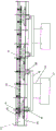
FIG. 1 is a schematic illustration of a catenary conveyor system with a transitional machine of the present invention;
FIG. 2 is a schematic structural view of the inboard horizontal catenary conveyor line 22 of the present invention;
FIG. 3 is a schematic view of the load car group stopper 35 of the present invention;
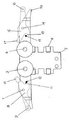
FIG. 4 is a schematic structural view of the load carrier of the present invention;
FIG. 5 is a schematic view of the load carrier of the present invention in a top view;
FIG. 6 is a schematic structural diagram of a limiting mechanism when a swing rod on the carrying trolley rises.
Detailed Description
The invention is described in detail below with reference to the accompanying drawings:
a heavy catenary chain conveying system with a transfer machine comprises an outer horizontal catenary chain conveying line 21 and an inner horizontal catenary chain conveying line 22 on the closed-cycle heavy catenary chain conveying line, wherein an outer accumulation area is arranged on the outer horizontal catenary chain conveying line 21, an inner accumulation area is arranged on the inner horizontal catenary chain conveying line 22, a transfer machine 23 is arranged between the tail end of the outer horizontal catenary chain conveying line 21 and the head end of the inner horizontal catenary chain conveying line 22, a plurality of groups of bearing trolley groups 24 are arranged on the heavy catenary chain conveying line, each bearing trolley group 24 is composed of a left bearing trolley 33 and a right bearing trolley 34 which are identical in structure, a bearing beam 25 is hung between a vertical hanging plate of the left bearing trolley 33 and a vertical hanging plate of the right bearing trolley 34, a hanging rod 26 is arranged on the bearing beam 25, a workpiece 27 is hung at the lower end of the hanging rod 26, the left bearing trolley 33 and the right bearing trolley 34 are movably arranged on a bearing trolley walking track 28, a catenary running track 29 is arranged right above the bearing trolley running track 28, a running catenary 30 is arranged on the catenary running track 29, pushing heads are arranged on the catenary 30 at intervals, when a bearing trolley group 24 runs on an inner horizontal catenary conveyor line 22 conveyed from right to left, a left swing rod lifting claw 10 on a left bearing trolley 33 in the bearing trolley group 24 at the front is abutted against the front pushing head 31, and a left swing rod lifting claw 10 on a left bearing trolley 33 in the bearing trolley group 24 at the rear is abutted against the rear pushing head 32; when the bearing trolley group 24 runs on the outer horizontal catenary conveyor line 21 which is conveyed from left to right, the right swing rod lifting claw 17 on the right bearing trolley 34 in the bearing trolley group 24 running at the front is abutted with the front pusher, and the right swing rod lifting claw 17 on the right bearing trolley 34 in the bearing trolley group 24 running at the rear is abutted with the rear pusher; an inner accumulation area on the inner horizontal catenary conveyor line 22 and an outer accumulation area on the outer horizontal catenary conveyor line 21 are respectively provided with a bearing trolley group stopper 35, and a telescopic blocking rod 36 is arranged on the bearing trolley group stopper 35.
The body of the left bearing trolley 33 is composed of an outer side horizontal frame plate 1, an inner side horizontal frame plate 2, a front trolley traveling wheel pair 3 and a rear trolley traveling wheel pair 4, a vertical hanging plate 5 is fixedly arranged on the lower bottom surface of the middle part of the trolley frame body, a left swing rod hinge pin 7 is arranged between the left end of the front side vertical type frame plate 1 and the left end of the rear side vertical type frame plate 2, the left swing rod hinge pin 7 is hinged with the middle part of a left swing rod 8, a left swing link counterweight idler wheel 9 is arranged at the left end of the left swing link 8, a left swing link lifting claw 10 is arranged at the right end of the left swing link 8, a left swing rod lifting limit pin shaft 12 is arranged between the front side vertical frame plate 1 and the rear side vertical frame plate 2 below the right side of the left swing rod hinge pin shaft 7, a left swing rod lifting limiting groove 11 is formed in the right side of the lower end of the left swing rod 8, and a left inclined fork 13 is arranged at the left end of the front side vertical frame plate 1; a right swing rod hinge pin shaft 14 is arranged between the right end of the front side vertical frame plate 1 and the right end of the rear side vertical frame plate 2, the right swing rod hinge pin shaft 14 is hinged with the middle part of a right swing rod 15, a right swing rod counterweight idler wheel 16 is arranged at the right end of the right swing rod 15, a right swing rod lifting claw 17 is arranged at the left end of the right swing rod 15, a right swing rod lifting limiting pin shaft 19 is arranged between the front side vertical frame plate 1 and the rear side vertical frame plate 2 below the left side of the right swing rod hinge pin shaft 14, a right swing rod lifting limiting groove 18 is arranged at the left side of the lower end of the right swing rod 15, and a right inclined fork 20 is arranged at the right end of the rear side vertical; the right swing link lifting claw 17 on the left load bearing trolley 33 is in a descending state, and the left swing link lifting claw 10 on the right load bearing trolley 34 is in a descending state.
A pair of walking guide wheels 6 is arranged on the vertical hanging plate 5; a pair of running guide wheels is arranged between the two I-steel guide rails of the running track 28 of the bearing trolley.
A trolley group walking and accumulating method in a catenary chain conveying system with a moving machine comprises bearing trolleys with the same structure, wherein each two bearing trolleys form a bearing trolley group 24, a plurality of groups of bearing trolley groups 24 are arranged in the catenary chain conveying system in a closed cycle at intervals, a right swing rod lifting claw 17 on a left bearing trolley 33 in each group of bearing trolley groups 24 is in a descending state, a left swing rod lifting claw 10 on a right bearing trolley 34 is in the descending state, namely swing rod lifting claws on the inner sides of two bearing trolleys in the bearing trolley groups 24 are in the descending state so as to ensure that the swing rod lifting claws are not in contact with a pushing head on a rotating chain 30, thus ensuring that the walking and accumulating actions of the two bearing trolley groups in two directions are completed, and a manual pin body can be arranged on each bearing trolley to lower and fix the swing arm on the inner side;
the invention is under the condition that the space of the workshop is limited, meet the problem that two arc-shaped transition lines can not be arranged in the catenary chain conveying system, adopt the design scheme of arranging the transfer machine between two parallel lines, make the bearing trolley group running to the end of the front side parallel conveying line not need to enter into the arc-shaped conveying line, but pass the transfer machine, transfer to the head end of the rear side parallel conveying line, enter the straight line conveying line of the rear side directly, convey and accumulate, in the same catenary chain conveying system of the invention, the running directions of the two parallel conveying lines are opposite;
when the bearing trolley group 24 walks on the bearing trolley walking track 28 on the outer horizontal catenary conveyor line 21 on the closed-cycle heavy catenary conveyor line from left to right, the walking power of the front bearing trolley group 24 realizes the walking of the trolley group through the contact and the cooperation of the front pushing head on the catenary 30 and the right swing rod lifting claw 17 on the right bearing trolley 34 in the front bearing trolley group 24;
when the front bearing trolley group 24 walks from left to right to an outer accumulating and releasing area arranged on the outer horizontal catenary conveyor line 21, a telescopic blocking rod 36 arranged on a bearing trolley group stopper 35 arranged on the outer accumulating and releasing area extends out, the telescopic blocking rod 36 lifts a right swing rod counterweight roller 16 on a right bearing trolley 34 in the front bearing trolley group 24, a right swing rod lifting claw 17 arranged at the left end of a right swing rod 15 is lowered to be separated from contact with a pushing head on a catenary, and the front bearing trolley group 24 loses power and stops; at the moment, the rear bearing trolley group 24 still walks from left to right along with the catenary, and after the right swing rod counterweight roller 16 on the right bearing trolley 34 in the rear bearing trolley group 24 walks and collides with the left inclined fork 13 on the left bearing trolley 33 in the front bearing trolley group 24 which is stopped, the right swing rod counterweight roller 16 is lifted by the left inclined fork 13, so that the right swing rod 15 on the right bearing trolley 34 in the rear bearing trolley group 24 rotates anticlockwise, the right swing rod lifting claw 17 is separated from the rear pushing head, the rear bearing trolley group 24 loses power and stops, and the accumulation of the two bearing trolley groups is realized;
after the carrier trolley group 24 walking at the tail end of the outer horizontal catenary conveyor line 21 enters the transfer machine 23, the carrier trolley group 24 is horizontally transferred to the head end of the inner horizontal catenary conveyor line 22 along the front-back direction by the transfer machine 23, then enters the inner horizontal catenary conveyor line 22, and is matched with a catenary push head walking leftwards to realize walking on the inner horizontal catenary conveyor line 22;
when the bearing trolley group 24 walks on the bearing trolley walking track 28 on the inner horizontal catenary chain conveyor line 22 on the closed-cycle heavy catenary chain conveyor line from right to left, the walking power of the front bearing trolley group 24 is realized by the contact cooperation of the front pushing head 31 on the catenary chain 30 and the left swing rod lifting claw 10 on the left bearing trolley 33 in the front bearing trolley group 24; the walking power of the rear bearing trolley group 24 is realized by the contact and the cooperation of a rear pushing head 32 on the catenary 30 and a left swing rod lifting claw 10 on a left bearing trolley 33 in the rear bearing trolley group 24;
when the front bearing trolley group 24 enters the inner accumulating area arranged on the inner horizontal catenary chain conveyor line 22, the telescopic blocking rod 36 arranged on the bearing trolley group stopper 35 on the inner accumulating area extends out to lift the left swing link counterweight roller 9 on the left bearing trolley 33 in the front bearing trolley group 24, so that the left swing link 8 rotates clockwise, the left swing link lifting claw 10 is separated from the front pushing head 31, the power of the front bearing trolley group 24 is lost to stop, at the moment, the rear bearing trolley group 24 still walks from right to left along with the catenary, when the left swing link counterweight roller 9 on the left bearing trolley 33 in the rear bearing trolley group 24 walks to touch the right inclined fork 20 on the right bearing trolley 34 in the front bearing trolley group 24 which is stopped, the left swing link counterweight roller 9 is lifted by the right inclined fork 20, so that the left swing link counterweight roller 8 on the left bearing trolley 33 in the rear bearing trolley group 24 rotates clockwise, separating the left swing rod lifting claw 10 from the rear pushing head 32, and stopping the rear bearing trolley group 24 after losing power to realize the accumulation and release of the two bearing trolley groups;
the catenary 30 on the outer horizontal catenary conveyor line 21 in the closed-cycle heavy catenary conveyor line runs from left to right, the inner horizontal catenary conveyor line 22 in the closed-cycle heavy catenary conveyor line runs from right to left, and the bearing trolley group 24 is moved by a moving machine 23 arranged between the tail end of the outer horizontal catenary conveyor line 21 and the head end of the inner horizontal catenary conveyor line 22; the left hand carrier trolley 33 and the right hand carrier trolley 34 in the carrier trolley group 24 on the carrier trolley running rail 28 on the inner horizontal catenary conveyor line 22 move in parallel from the outer horizontal catenary conveyor line 21 to the inner horizontal catenary conveyor line 22 in groups.
Claims (1)
1. The utility model provides a dolly group walking and long-pending method of putting in catenary chain conveying system with machine of dividing a word with a hyphen at a glance, includes the bearing trolley that the structure is the same, every two bearing trolleys constitute one and bear dolly group (24), be provided with multiunit bearing dolly group (24) in closed endless catenary chain conveying system at intervals, right pendulum rod lifting claw (17) on left side bearing trolley (33) in every group bearing dolly group (24) are in the state that descends, left pendulum rod lifting claw (10) on right side bearing trolley (34) are in the state that descends, its characterized in that:
when the bearing trolley group (24) walks on a bearing trolley walking track (28) on an inner horizontal catenary conveyor line (22) on a closed-cycle heavy catenary conveyor line from right to left, the walking power of the front bearing trolley group (24) is realized by the contact and matching of a front push head (31) on a catenary (30) and a left swing rod lifting claw (10) on a left bearing trolley (33) in the front bearing trolley group (24); the walking power of the rear bearing trolley group (24) is realized by the contact and the matching of a rear pushing head (32) on the catenary chain (30) and a left swing rod lifting claw (10) on a left bearing trolley (33) in the rear bearing trolley group (24);
when a front bearing trolley group (24) enters an inner accumulation area arranged on an inner horizontal catenary conveyor line (22), a telescopic blocking rod (36) arranged on a bearing trolley group stopper (35) on the inner accumulation area extends out to lift a left swing rod counterweight roller (9) on a left bearing trolley (33) in the front bearing trolley group (24), so that a left swing rod (8) rotates clockwise, a left swing rod lifting claw (10) is separated from a front pushing head (31), the front bearing trolley group (24) loses power and stops, at the moment, the rear bearing trolley group (24) still walks from right to left along with the catenary, and after the left swing rod counterweight roller (9) on the left bearing trolley (33) in the rear bearing trolley group (24) runs and is connected to a stopped right inclined fork (20) on a right bearing trolley (34) in the front bearing trolley group (24), a left swing rod counterweight roller (9) is lifted by a right inclined shovel fork (20), so that a left swing rod (8) on a left bearing trolley (33) in a rear bearing trolley group (24) rotates clockwise, a left swing rod lifting claw (10) is separated from a rear pushing head (32), the rear bearing trolley group (24) loses power and stops, and the accumulation of the two bearing trolley groups is realized;
the catenary (30) on the outer horizontal catenary conveyor line (21) in the closed-cycle heavy catenary conveyor line runs from left to right, the inner horizontal catenary conveyor line (22) in the closed-cycle heavy catenary conveyor line runs from right to left, and the bearing trolley group (24) is moved by a moving machine (23) arranged between the tail end of the outer horizontal catenary conveyor line (21) and the head end of the inner horizontal catenary conveyor line (22); the left bearing trolley (33) and the right bearing trolley (34) in the bearing trolley group (24) on the bearing trolley walking track (28) on the inner horizontal catenary conveyor line (22) are moved to the inner horizontal catenary conveyor line (22) in parallel in groups from the outer horizontal catenary conveyor line (21).
Priority Applications (1)
| Application Number | Priority Date | Filing Date | Title |
|---|---|---|---|
| CN202010382020.5A CN111605988A (en) | 2020-05-08 | 2020-05-08 | Method for walking and accumulating trolley group in catenary conveying system with transfer machine |
Applications Claiming Priority (1)
| Application Number | Priority Date | Filing Date | Title |
|---|---|---|---|
| CN202010382020.5A CN111605988A (en) | 2020-05-08 | 2020-05-08 | Method for walking and accumulating trolley group in catenary conveying system with transfer machine |
Publications (1)
| Publication Number | Publication Date |
|---|---|
| CN111605988A true CN111605988A (en) | 2020-09-01 |
Family
ID=72201828
Family Applications (1)
| Application Number | Title | Priority Date | Filing Date |
|---|---|---|---|
| CN202010382020.5A Pending CN111605988A (en) | 2020-05-08 | 2020-05-08 | Method for walking and accumulating trolley group in catenary conveying system with transfer machine |
Country Status (1)
| Country | Link |
|---|---|
| CN (1) | CN111605988A (en) |
Cited By (1)
| Publication number | Priority date | Publication date | Assignee | Title |
|---|---|---|---|---|
| CN113233098A (en) * | 2021-04-28 | 2021-08-10 | 诸城万通铸造装备工程有限公司 | Workpiece conveying device for shot blasting machine |
Citations (6)
| Publication number | Priority date | Publication date | Assignee | Title |
|---|---|---|---|---|
| JPS5486183A (en) * | 1977-12-20 | 1979-07-09 | Houkoku Chien Kk | Chain for tow conveyor |
| CN2895330Y (en) * | 2006-03-24 | 2007-05-02 | 承德光大输送机有限公司 | Ground storage trolley conveyor |
| CN101624133A (en) * | 2009-08-03 | 2010-01-13 | 山西东方智能物流股份有限公司 | Heavy power and free overhead conveyer |
| CN103771102A (en) * | 2014-02-26 | 2014-05-07 | 盐城东方天成机械有限公司 | Forward accumulation device for ground transportation line |
| CN205855223U (en) * | 2016-08-12 | 2017-01-04 | 苏州市巨力输送机械厂 | A kind of carrying dolly and induction system |
| CN110053933A (en) * | 2019-04-25 | 2019-07-26 | 山东拓展智能装备制造有限公司 | One kind is electronic to accumulate vehicle group conveyer |
-
2020
- 2020-05-08 CN CN202010382020.5A patent/CN111605988A/en active Pending
Patent Citations (6)
| Publication number | Priority date | Publication date | Assignee | Title |
|---|---|---|---|---|
| JPS5486183A (en) * | 1977-12-20 | 1979-07-09 | Houkoku Chien Kk | Chain for tow conveyor |
| CN2895330Y (en) * | 2006-03-24 | 2007-05-02 | 承德光大输送机有限公司 | Ground storage trolley conveyor |
| CN101624133A (en) * | 2009-08-03 | 2010-01-13 | 山西东方智能物流股份有限公司 | Heavy power and free overhead conveyer |
| CN103771102A (en) * | 2014-02-26 | 2014-05-07 | 盐城东方天成机械有限公司 | Forward accumulation device for ground transportation line |
| CN205855223U (en) * | 2016-08-12 | 2017-01-04 | 苏州市巨力输送机械厂 | A kind of carrying dolly and induction system |
| CN110053933A (en) * | 2019-04-25 | 2019-07-26 | 山东拓展智能装备制造有限公司 | One kind is electronic to accumulate vehicle group conveyer |
Cited By (1)
| Publication number | Priority date | Publication date | Assignee | Title |
|---|---|---|---|---|
| CN113233098A (en) * | 2021-04-28 | 2021-08-10 | 诸城万通铸造装备工程有限公司 | Workpiece conveying device for shot blasting machine |
Similar Documents
| Publication | Publication Date | Title |
|---|---|---|
| CN102991979B (en) | Self-propelling car system | |
| CN102991978B (en) | Self-propelling car system | |
| CN211140612U (en) | RGV dolly | |
| CN111532673A (en) | Heavy catenary chain conveying system with transfer machine and capable of preventing bearing trolley group from turning around | |
| CN202387736U (en) | Rapid roller exchanging machine of middle roller of work roller | |
| CN111453364A (en) | Automatic overturning and transverse moving equipment for long component | |
| CN102561768A (en) | Trackless comb-like trolley with gear lifting devices | |
| CN205294327U (en) | What fork advancing mechanism was cut in area has a rail loading dolly | |
| CN111605988A (en) | Method for walking and accumulating trolley group in catenary conveying system with transfer machine | |
| CN212268562U (en) | Bearing trolley for realizing bidirectional walking accumulation on catenary conveyor line | |
| CN110479998A (en) | A kind of aerial molten iron transhipment and ladle-to-ladle device | |
| CN112081439B (en) | Method for storing and taking vehicles by using transverse moving trolley with telescopic automatic leveling device | |
| CN212580880U (en) | Automatic overturning and transverse moving equipment for long component | |
| CN212502370U (en) | Heavy catenary conveying system with moving machine | |
| CN213059103U (en) | Lifting and horizontal moving cross-over system for strip conveying | |
| CN116040477B (en) | Crane for automatic oxidation workshop | |
| CN212502369U (en) | Heavy catenary chain conveying system with transfer machine and capable of preventing bearing trolley group from turning around | |
| CN107826653B (en) | Flexible conveying device for corner conveying | |
| CN111532675A (en) | Heavy catenary conveying system with moving machine | |
| CN111605987A (en) | Walking and accumulating method of head-dropping-free trolley group in catenary conveying system with moving machine | |
| CN215665299U (en) | Single motor driven four-way shuttle board | |
| CN107237609B (en) | riser catwalk | |
| CN111532674A (en) | Bearing trolley for realizing bidirectional walking accumulation on catenary conveyor line | |
| CN214827425U (en) | Automatic loading machine for bagged materials | |
| CN215665297U (en) | Three-station swing arm mechanism on single-motor-driven four-way shuttle plate |
Legal Events
| Date | Code | Title | Description |
|---|---|---|---|
| PB01 | Publication | ||
| PB01 | Publication | ||
| SE01 | Entry into force of request for substantive examination | ||
| SE01 | Entry into force of request for substantive examination | ||
| RJ01 | Rejection of invention patent application after publication | ||
| RJ01 | Rejection of invention patent application after publication |
Application publication date: 20200901 |