CN111590326A - High efficiency drilling and tapping robot - Google Patents
High efficiency drilling and tapping robot Download PDFInfo
- Publication number
- CN111590326A CN111590326A CN202010415958.2A CN202010415958A CN111590326A CN 111590326 A CN111590326 A CN 111590326A CN 202010415958 A CN202010415958 A CN 202010415958A CN 111590326 A CN111590326 A CN 111590326A
- Authority
- CN
- China
- Prior art keywords
- pipe
- fixed
- workpiece
- mounting plate
- along
- Prior art date
- Legal status (The legal status is an assumption and is not a legal conclusion. Google has not performed a legal analysis and makes no representation as to the accuracy of the status listed.)
- Granted
Links
Images


Classifications
-
- B—PERFORMING OPERATIONS; TRANSPORTING
- B23—MACHINE TOOLS; METAL-WORKING NOT OTHERWISE PROVIDED FOR
- B23P—METAL-WORKING NOT OTHERWISE PROVIDED FOR; COMBINED OPERATIONS; UNIVERSAL MACHINE TOOLS
- B23P23/00—Machines or arrangements of machines for performing specified combinations of different metal-working operations not covered by a single other subclass
- B23P23/02—Machine tools for performing different machining operations
-
- B—PERFORMING OPERATIONS; TRANSPORTING
- B23—MACHINE TOOLS; METAL-WORKING NOT OTHERWISE PROVIDED FOR
- B23Q—DETAILS, COMPONENTS, OR ACCESSORIES FOR MACHINE TOOLS, e.g. ARRANGEMENTS FOR COPYING OR CONTROLLING; MACHINE TOOLS IN GENERAL CHARACTERISED BY THE CONSTRUCTION OF PARTICULAR DETAILS OR COMPONENTS; COMBINATIONS OR ASSOCIATIONS OF METAL-WORKING MACHINES, NOT DIRECTED TO A PARTICULAR RESULT
- B23Q1/00—Members which are comprised in the general build-up of a form of machine, particularly relatively large fixed members
- B23Q1/25—Movable or adjustable work or tool supports
-
- B—PERFORMING OPERATIONS; TRANSPORTING
- B23—MACHINE TOOLS; METAL-WORKING NOT OTHERWISE PROVIDED FOR
- B23Q—DETAILS, COMPONENTS, OR ACCESSORIES FOR MACHINE TOOLS, e.g. ARRANGEMENTS FOR COPYING OR CONTROLLING; MACHINE TOOLS IN GENERAL CHARACTERISED BY THE CONSTRUCTION OF PARTICULAR DETAILS OR COMPONENTS; COMBINATIONS OR ASSOCIATIONS OF METAL-WORKING MACHINES, NOT DIRECTED TO A PARTICULAR RESULT
- B23Q11/00—Accessories fitted to machine tools for keeping tools or parts of the machine in good working condition or for cooling work; Safety devices specially combined with or arranged in, or specially adapted for use in connection with, machine tools
- B23Q11/0042—Devices for removing chips
- B23Q11/0046—Devices for removing chips by sucking
-
- B—PERFORMING OPERATIONS; TRANSPORTING
- B23—MACHINE TOOLS; METAL-WORKING NOT OTHERWISE PROVIDED FOR
- B23Q—DETAILS, COMPONENTS, OR ACCESSORIES FOR MACHINE TOOLS, e.g. ARRANGEMENTS FOR COPYING OR CONTROLLING; MACHINE TOOLS IN GENERAL CHARACTERISED BY THE CONSTRUCTION OF PARTICULAR DETAILS OR COMPONENTS; COMBINATIONS OR ASSOCIATIONS OF METAL-WORKING MACHINES, NOT DIRECTED TO A PARTICULAR RESULT
- B23Q15/00—Automatic control or regulation of feed movement, cutting velocity or position of tool or work
- B23Q15/20—Automatic control or regulation of feed movement, cutting velocity or position of tool or work before or after the tool acts upon the workpiece
- B23Q15/22—Control or regulation of position of tool or workpiece
- B23Q15/24—Control or regulation of position of tool or workpiece of linear position
Abstract
The invention relates to a high-efficiency drilling and tapping robot which comprises a support, wherein a plurality of processing units are arranged on the support, and each processing unit comprises a first linear module; a first sliding plate is arranged on the first linear module, a lifting driving piece is arranged on the first sliding plate, and a first mounting plate is arranged on the lifting driving piece; the first mounting plate is provided with a plurality of sliding blocks, the sliding blocks are rotatably connected with rotating pieces, the two adjacent groups of rotating pieces are wound with the same belt, the inner sides of the belts are provided with tightening rods, the tightening rods are fixedly provided with telescopic rods, and the telescopic ends of the telescopic rods are fixedly provided with limit rings; the first mounting plate is fixedly provided with a first motor, a first driving piece and a second driving piece. The multiple groups of processing units can process the workpiece at the same time, and each processing unit can perform multiple groups of drilling and tapping at the same time; the first driving piece and the second driving piece can simultaneously adjust the distance between every two groups of adjacent rotating pieces. The invention improves the processing efficiency of the workpiece.
Description
Technical Field
The invention relates to the technical field of metal processing equipment, in particular to a high-efficiency drilling and tapping robot.
Background
Drilling and tapping on existing workpieces is typically done by workers holding drills and tappers.
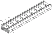
As shown in fig. 1, a large steel workpiece 1 is hollow, and has a plurality of through grooves 11 milled on its side and surface. In the process of processing the workpiece 1, a drilling machine is required to drill a plurality of blind holes 12 which are sequentially arranged along the length direction of the workpiece 1 on both sides of the workpiece, and then tapping is carried out on the basis of the blind holes 12 through a tapping machine.
However, the length of the workpiece is generally 5000-; if a drilling and tapping machine tool is used to machine a workpiece, the machining range of the drilling and tapping machine tool is about 2 meters, so that the workpiece needs to be moved many times and the positions of a drill bit and a tapping head need to be calibrated many times, which is inconvenient, and the machining efficiency is still low, so that improvement is needed.
Disclosure of Invention
Aiming at the defects in the prior art, the invention aims to provide a high-efficiency drilling and tapping robot, which improves the processing efficiency of workpieces.
The above object of the present invention is achieved by the following technical solutions: a high-efficiency drilling and tapping robot comprises a support, wherein a plurality of processing units which are sequentially arranged along the length direction of a workpiece are mounted on the support, and each processing unit comprises a first linear module which extends along the length direction of the workpiece; a first sliding plate is arranged on the first linear module, a lifting driving piece is arranged on the first sliding plate, and a first mounting plate is arranged on the lifting driving piece; the first mounting plate is provided with a plurality of sliding blocks, one sliding block positioned on the edge part is fixed on the first mounting plate, and the rest sliding blocks are connected to the first mounting plate in a sliding manner along the length direction of the workpiece; the sliding block is rotatably connected with rotating parts, one half of the rotating parts are drill bits, the other half of the rotating parts are tapping heads, and the drill bits are arranged on one side of all the tapping heads; the two adjacent groups of rotating parts are wound with the same belt, the inner sides of the belts are provided with tightening rods, telescopic rods are fixed on the tightening rods, and limiting rings for the rotating parts to be rotatably embedded are fixed on the telescopic ends of the telescopic rods; the same moving plate is arranged on all the tightening rods, and the tightening rods are connected to the moving plate in a sliding manner along the length direction of the workpiece; the first mounting plate is fixedly provided with a first motor, a first driving part for driving the movable plate to move along the width direction of the workpiece, and a second driving part for driving the other slide block positioned at the edge part to move along the length direction of the workpiece, and an output shaft of the first motor is fixedly connected with a rotating part fixed on the slide block on the first mounting plate.
By adopting the technical scheme, in the process of processing a workpiece, a plurality of blind holes are drilled below each processing unit through a handheld drilling machine, and the number of the blind holes is equal to that of tapping heads; then the first linear module drives the first sliding plate to move, so that the drill bit is positioned right above the unprocessed part of the workpiece, and the tapping head corresponds to the blind hole; then starting a first motor, and under the action of a belt, all rotating pieces synchronously rotate in the same direction, and the limiting ring ensures that the rotating pieces are not easy to shake in the rotating process; then, the first mounting plate is driven to descend by the lifting driving piece, the drill bit is used for drilling a hole in the workpiece, and the tapping head is used for tapping the drilled blind hole; the processing units can process the workpieces at the same time, and each processing unit can simultaneously perform multiple groups of drilling and tapping, so that the processing efficiency of the workpieces is improved; when one side of the workpiece is machined, the workpiece is moved, and the other side of the workpiece can be machined.
When the blind hole pitch of required processing changes, drive the motion of tightening rod through first driving piece to drive the slider motion through second driving piece, the length of all telescopic links will all change this moment, and all belts all keep the tensioning state, and make corresponding tightening rod and slider move along the length direction of work piece, make the interval between the adjacent rotating member change.
Because both ends of all telescopic links move synchronously, the lengths of all telescopic links are equal; because the included angle between the connecting line of two adjacent groups of rotating members and the telescopic rod is invariable, the length of the belt is fixed, and the sliding block and the tightening rod can only slide along the length direction of the workpiece, so that the intervals between every two adjacent groups of rotating members are equal. Therefore, the distance between every two groups of adjacent rotating parts can be adjusted simultaneously through the first driving part and the second driving part, the operation is convenient, and the processing efficiency of the workpiece is further improved.
The present invention in a preferred example may be further configured to: a first thread through groove extending in the vertical direction is formed in the limiting ring, and a first bolt tightly abutting against the first mounting plate is matched with the inner thread of the first thread through groove.
Through adopting above-mentioned technical scheme, after the interval adjustment between adjacent two sets of rotating parts was accomplished, with first bolt screw thread cooperation in first screw thread logical groove and support tightly in first mounting panel, can fix the spacing ring locking to further make the rotating part be difficult for rocking.
The present invention in a preferred example may be further configured to: and a cooling pipe is fixed on the sliding block, the pipe orifice of the cooling pipe faces the rotating part, and the cooling pipe is connected with an external cooling water tank through a first hose.
Through adopting above-mentioned technical scheme, at the in-process that the rotating member processed the work piece, the cooling tube will be to the department of processing injection cooling water to the condition that the rotating member damaged has been reduced and has been taken place.
The present invention in a preferred example may be further configured to: the processing units are sequentially provided with two groups along the width direction of the workpiece.
Through adopting above-mentioned technical scheme, two sets of processing units can be processed the both sides of work piece upper surface simultaneously to the machining efficiency of work piece has further been improved.
The present invention in a preferred example may be further configured to: two sets of along work piece width direction setting be equipped with the second sharp module of installing on the support between the processing unit, install the second slide on the second sharp module, be equipped with fixed pipe on the second slide, fixed pipe has the first chip suction pipe that extends along the horizontal direction through the connecting pipe intercommunication, and the mouth of pipe of first chip suction pipe is down and just to the upper surface of work piece, and fixed pipe passes through the second hose and links to each other with outside chip suction machine.
Through adopting above-mentioned technical scheme, carry out the in-process of processing at the rotating member to the work piece, the second straight line module will drive the motion of second slide for first inhaling bits pipe removes to processing completion department, then the sweeps of work piece upper surface will enter into outside through first inhaling bits pipe, connecting pipe, fixed pipe and second hose and inhale the bits built-in, has realized the absorption to the sweeps.
The present invention in a preferred example may be further configured to: and a third electric cylinder is fixed on the second sliding plate, a piston rod of the third electric cylinder extends along the vertical direction and is fixed with a second mounting plate, and a fixed pipe is fixed on the second mounting plate.
Through adopting above-mentioned technical scheme, the third electric jar can drive the second mounting panel and go up and down for first inhaling bits pipe can carry out the sweeps to the work piece of co-altitude not and absorb.
The present invention in a preferred example may be further configured to: the connecting pipe is rotatably embedded in the fixed pipe around the axis of the connecting pipe, and the fixed pipe is provided with a driving assembly for driving the connecting pipe to rotate; first suction dust pipe passes through the third hose and communicates in the connecting pipe, and first suction dust pipe slides along the horizontal direction and connects in the connecting pipe, is equipped with on the connecting pipe to be used for the retaining member fixed with first suction dust pipe locking.
Through adopting above-mentioned technical scheme, it is rotatory around self axis to drive the subassembly, and first inhaling bits pipe can slide and fix on the connecting pipe through retaining member locking along the horizontal direction for the rotation range of first inhaling bits pipe changes, thereby makes first inhaling bits pipe can absorb the sweeps on the work piece of different width.
The present invention in a preferred example may be further configured to: the lower end of the connecting pipe is provided with a second scrap suction pipe extending along the horizontal direction, the second scrap suction pipe is communicated with the connecting pipe through a fourth hose, and the pipe orifice of the second scrap suction pipe faces downwards and is right opposite to the inner wall of the bottom of the workpiece.
By adopting the technical scheme, in the process of milling, drilling and tapping the appearance of the workpiece, part of the waste chips enter the inner side of the workpiece through the through groove; when the third electric cylinder drives the second mounting plate to descend, the second chip suction pipe enters the inner side of the workpiece; when the driving assembly drives the connecting pipe to rotate, the second scrap suction pipe also rotates to suck and remove the scraps at the bottom of the inner side of the workpiece.
In summary, the invention has the following beneficial technical effects:
1. the processing units are arranged, so that the workpieces can be processed at the same time, and each processing unit can simultaneously perform multiple groups of drilling and tapping, so that the processing efficiency of the workpieces is improved;
2. the sliding block, the tightening rod, the belt, the telescopic rod, the movable plate, the first driving piece and the second driving piece are arranged, the distance between every two adjacent groups of rotating pieces can be adjusted simultaneously through the first driving piece and the second driving piece, the operation is convenient, and therefore the machining efficiency of the workpiece is further improved;
3. the arrangement of the limiting ring and the first bolt ensures that the rotating piece is not easy to shake;
4. the second linear module, the second sliding plate, the fixed pipe, the connecting pipe and the first chip suction pipe are arranged, so that the waste chips on the upper surface of the workpiece enter the external chip suction machine through the first chip suction pipe, the connecting pipe, the fixed pipe and the second hose;
5. the third electric cylinder and the second mounting plate are arranged, so that the first scrap suction pipe can suck and remove scraps on workpieces with different heights;
6. the driving assembly and the locking piece are arranged, so that the first scrap suction pipe can suck and remove the scraps on the workpieces with different widths;
7. the setting of second chip suction pipe can be absorbed the sweeps of the inboard bottom of work piece.
Drawings
FIG. 1 is a schematic structural view of a prior art steel workpiece;
FIG. 2 is a schematic view of the overall structure in the embodiment of the present invention;
FIG. 3 is a schematic diagram showing the structure of the mounting component on the first mounting plate in an embodiment of the present invention;
FIG. 4 is a schematic structural view showing a lower surface of a first mounting plate in the embodiment of the present invention;
FIG. 5 is a schematic view showing the structure of a rotary member and a tightening rod in the embodiment of the present invention;
FIG. 6 is a schematic cross-sectional view of a workpiece in an embodiment of the invention;
FIG. 7 is a schematic structural view showing a first chip suction pipe in the embodiment of the invention;
FIG. 8 is a schematic view showing the structure of a second dust suction pipe in the embodiment of the present invention.
Reference numerals: 1. a workpiece; 11. a through groove; 12. blind holes; 2. a support; 3. a processing unit; 31. a first linear module; 32. a first slide plate; 33. a fourth electric cylinder; 34. a first mounting plate; 341. a first dovetail groove; 35. a slider; 351. a first dovetail block; 36. a rotating member; 361. a belt groove; 37. a belt; 38. a first motor; 39. a cooling tube; 391. a first hose; 4. a first electric cylinder; 41. moving the plate; 411. a second dovetail groove; 42. tightening the rod; 421. a second dovetail block; 43. a telescopic rod; 44. a limiting ring; 45. a first bolt; 5. a second electric cylinder; 6. a second linear module; 61. a second slide plate; 62. a third electric cylinder; 63. a second mounting plate; 64. a fixed tube; 641. a second hose; 65. a connecting pipe; 651. a third dovetail block; 652. a second bolt; 653. rotating the block; 654. an upper baffle plate; 655. a lower baffle plate; 656. a fourth dovetail block; 657. a third bolt; 66. a first crumb absorbing tube; 661. a third dovetail groove; 67. a third hose; 68. a second scrap suction pipe; 681. a wear-resistant block; 682. a fourth dovetail groove; 69. a fourth hose; 7. a driving component; 71. a driven bevel gear; 72. a drive bevel gear; 73. a second motor.
Detailed Description
The present invention will be described in further detail with reference to the accompanying drawings.
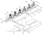
As shown in fig. 2, the high-efficiency drilling and tapping robot comprises a support 2, wherein a plurality of processing units 3 which are sequentially arranged along the length direction of a workpiece 1 are mounted on the support 2, and two groups of processing units 3 are sequentially arranged along the width direction of the workpiece 1.
As shown in fig. 2 and 3, the processing unit 3 includes a first linear module 31 extending along the length direction of the workpiece 1, a first sliding plate 32 is mounted on the first linear module 31, a lifting driving member is fixed on the first sliding plate 32, the lifting driving member is a fourth electric cylinder 33, and a piston rod of the fourth electric cylinder 33 extends along the vertical direction and is fixed with a first mounting plate 34.
As shown in fig. 3 and 4, the first mounting plate 34 is provided with a plurality of sliders 35, and one of the sliders 35 located at the edge is fixed to the first mounting plate 34; the slide block 35 is rotatably connected with rotary members 36, half of the rotary members 36 are drill bits, the other half of the rotary members 36 are tapping heads, and the drill bits are arranged on one side of all the tapping heads; the same belt 37 is wound on the two adjacent groups of rotating members 36; a first motor 38 is fixed to the first mounting plate 34, and an output shaft of the first motor 38 is fixedly connected to a rotary member 36 fixed to a slider 35 on the first mounting plate 34.
In the processing process of the workpiece 1, firstly, drilling a plurality of blind holes 12 below each processing unit 3 by a handheld drilling machine, wherein the number of the blind holes 12 is equal to that of tapping heads; then, the first linear module 31 drives the first sliding plate 32 to move, so that the drill bit is positioned right above the unprocessed position of the workpiece 1, and the tapping head corresponds to the blind hole 12; then the first motor 38 is started, and all the rotating members 36 synchronously rotate in the same direction under the action of the belt 37; then the fourth electric cylinder 33 drives the first mounting plate 34 to descend, the drill bit drills the workpiece 1, and the tapping head taps the drilled blind hole 12; the plurality of sets of processing units 3 can process the workpiece 1 at the same time, and each processing unit 3 can simultaneously perform a plurality of sets of drilling and tapping, thereby improving the processing efficiency of the workpiece 1.
As shown in fig. 4 and 5, a cooling pipe 39 is fixed to the slide block 35, a nozzle of the cooling pipe 39 faces the rotary member 36, and the cooling pipe 39 is connected to an external cooling water tank through a first hose 391. During the process of the rotating member 36 for processing the workpiece 1, the cooling pipe 39 sprays cooling water to the processing position, thereby reducing the occurrence of damage to the rotating member 36.
As shown in fig. 4 and 5, a tightening rod 42 is disposed inside the belt 37, and belt grooves 361 are disposed on the side walls of the rotating member 36 and the tightening rod 42, so that the belt 37 is not prone to shake up and down; the telescopic rod 43 is fixed on the tightening rod 42; the telescopic rod 43 comprises a fixed cylinder fixed on the tightening rod 42 and a slide rod embedded in the fixed cylinder in a sliding manner, one end of the slide rod extending out of the fixed cylinder is the telescopic end of the telescopic rod 43, and a limit ring 44 for the rotary piece 36 to be embedded in a rotating manner is fixed on the telescopic end of the telescopic rod 43, so that the rotary piece 36 is not easy to shake; and the angle between the connecting line of two adjacent groups of rotating parts 36 and the telescopic rod 43 is 90 degrees.
As shown in fig. 4 and 5, the same moving plate 41 is provided on all the tightening rods 42, and the second dovetail block 421 is fixed on the tightening rods 42; the moving plate 41 is provided with a second dovetail groove 411 extending along the length direction of the workpiece 1, and a second dovetail block 421 is slidably embedded in the second dovetail groove 411, so that the tightening rod 42 can only slide along the length direction of the workpiece 1. A first driving member is fixed on the first mounting plate 34, the first driving member is a first electric cylinder 4, and a piston rod of the first electric cylinder 4 extends along the width direction of the workpiece 1 and is fixedly connected to the moving plate 41.
As shown in fig. 4 and 5, except for the group of sliding blocks 35 fixed on the first mounting plate 34, the upper sides of the other sliding blocks 35 are fixed with first dovetail blocks 351, the lower surface of the first mounting plate 34 is provided with first dovetail grooves 341 extending along the length direction of the workpiece 1, and the first dovetail blocks 351 are slidably embedded in the first dovetail grooves 341 so that the sliding blocks 35 can only slide along the length direction of the workpiece 1. A second driving member is fixed on the first mounting plate 34, the second driving member is a second electric cylinder 5, and a piston rod of the second electric cylinder 5 extends along the length direction of the workpiece 1 and is fixedly connected to a slidable slide block 35 positioned at the edge.
When the hole pitch of the blind hole 12 to be processed is changed, the first electric cylinder 4 drives the tightening rod 42 to move, and the second electric cylinder 5 drives the sliding block 35 to move, at this time, the lengths of all the tightening rods 43 are changed, all the belts 37 are kept in a tensioning state, and the corresponding tightening rod 42 and the corresponding sliding block 35 are driven to move along the length direction of the workpiece 1, so that the pitch between the adjacent rotating pieces 36 is changed.
Because the lengths of all the telescopic rods 43 are equal, the included angle between the connecting line of two adjacent groups of rotating members 36 and the telescopic rods 43 is not changed, the length of the belt 37 is fixed, and the sliding block 35 and the tightening rod 42 can only slide along the length direction of the workpiece 1, so that the intervals between every two adjacent groups of rotating members 36 are equal. Therefore, the distance between every two adjacent groups of rotating parts 36 can be adjusted simultaneously through the extension and retraction of the first electric cylinder 4 and the second electric cylinder 5, the operation is convenient, and the processing efficiency of the workpiece 1 is further improved.
As shown in fig. 5, the limiting ring 44 is provided with a first threaded through groove extending in the vertical direction, and a first bolt 45 is screwed in the first threaded through groove. After the distance between two adjacent sets of rotating members 36 is adjusted, first bolt 45 is screwed into first threaded through groove and tightly supported on first mounting plate 34, and limiting ring 44 can be locked and fixed, so that rotating members 36 are further prevented from shaking.
As shown in fig. 6, a second linear module 6 fixed on the bracket 2 is arranged between two groups of processing units 3 arranged along the width direction of the workpiece 1, and a second sliding plate 61 is arranged on the second linear module 6; a third electric cylinder 62 is fixed on the lower surface of the second sliding plate 61, and a piston rod of the third electric cylinder 62 extends along the vertical direction and is fixed with a second mounting plate 63; a fixed pipe 64 is fixed to the lower surface of the second mounting plate 63, the fixed pipe 64 is communicated with a first chip suction pipe 66 extending in the horizontal direction through a connecting pipe 65, the orifice of the first chip suction pipe 66 faces downward and faces the upper surface of the workpiece 1, and the fixed pipe 64 is connected with an external chip suction machine through a second hose 641.
In the process that the rotating piece 36 processes the workpiece 1, the second linear module 6 and the third electric cylinder 62 drive the second sliding plate 61 to move, so that the first chip suction pipe 66 moves to the processing completion position, and then the waste chips on the upper surface of the workpiece 1 enter the external chip suction machine through the first chip suction pipe 66, the connecting pipe 65, the fixing pipe 64 and the second hose 641, so that the absorption and removal of the waste chips are realized.
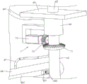
As shown in fig. 6 and 7, the connecting pipe 65 is rotatably embedded in the fixed pipe 64 around its axis, and the first dust suction pipe 66 is communicated with the connecting pipe 65 through a third hose 67; the fixed pipe 64 is provided with a driving component 7, the driving component 7 comprises a driven bevel gear 71 fixedly sleeved outside the connecting pipe 65, a driving bevel gear 72 meshed with the driven bevel gear 71 and a second motor 73 fixed on the outer wall of the fixed pipe 64, and an output shaft of the second motor 73 is fixedly embedded in the driving bevel gear 72. When the second motor 73 is started, the connecting pipe 65 drives the first scrap suction pipe 66 to rotate to suck the scraps on the upper surface of the workpiece 1.
As shown in fig. 7, a third dovetail block 651 is fixed to the outer wall of the connecting pipe 65, a third dovetail groove 661 extending in the horizontal direction is formed in the outer wall of the first chip suction pipe 66, and the third dovetail block 651 is slidably embedded in the third dovetail groove 661, so that the first chip suction pipe 66 can slide in the direction in which the third dovetail groove 661 is formed, the rotation range of the first chip suction pipe 66 is changed, and the first chip suction pipe 66 can suck and remove the chips on the workpieces 1 with different widths.
As shown in fig. 7, a second threaded through groove is formed in the third dovetail block 651, a locking member is matched with the inner thread of the second threaded through groove, and the locking member is a second bolt 652. After the position of the first chip suction pipe 66 is adjusted, the second bolt 652 is screwed into the second threaded through groove and abuts against the groove wall of the third dovetail groove 661, so that the first chip suction pipe 66 can be locked and fixed on the connecting pipe 65.
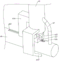
As shown in fig. 6, a second chip suction pipe 68 extending in the horizontal direction is provided at the lower end of the connecting pipe 65, the second chip suction pipe 68 is connected to the connecting pipe 65 via a fourth hose 69, the second chip suction pipe 68 has a nozzle facing downward and facing the inner wall of the bottom of the workpiece 1, and a nozzle is also provided at the end of the second chip suction pipe 68. When the third electric cylinder 62 drives the second mounting plate 63 to descend, the second chip suction pipe 68 enters the inner side of the workpiece 1; when the driving assembly 7 drives the connecting pipe 65 to rotate, the second scrap suction pipe 68 will also rotate and suck the scraps on the inner bottom of the workpiece 1.
As shown in fig. 8, the lower end of the connecting pipe 65 is rotatably connected with a rotating block 653, the second chip suction pipe 68 is arranged on the rotating block 653, the rotating plane of the second chip suction pipe 68 is parallel to the vertical plane, and a wear-resistant block 681 is fixed at one end of the second chip suction pipe 68 away from the connecting pipe 65; an upper baffle 654 and a lower baffle 655 which are respectively arranged at the upper side and the lower side of the second scrap suction pipe 68 are fixed on the connecting pipe 65, the upper baffle 654 is arranged horizontally, and the lower baffle 655 is arranged obliquely.
When the third electric cylinder 62 drives the second mounting plate 63 to descend, so that the second chip suction pipe 68 abuts against the inner bottom of the workpiece 1, the second chip suction pipe 68 rotates until the wear-resistant block 681 abuts against the inner bottom of the workpiece 1, and at this time, the upper side of the second chip suction pipe 68 abuts against the upper baffle 654, so that the second chip suction pipe 68 is not prone to shaking and can rotate to suck the waste chips at the inner bottom of the workpiece 1. Because the second scrap suction pipe 68 is abutted against the lower baffle 655 in a normal state, the second scrap suction pipe 68 is in an inclined state at the moment, and the length range which can be selected by the second scrap suction pipe 68 is larger, so that the suction effect on the bottom scraps on the inner side of the workpiece 1 is improved.
As shown in fig. 8, a fourth dovetail block 656 is fixed to the rotation block 653; the outer wall of the second chip suction pipe 68 is provided with a fourth dovetail groove 682 extending along the axial direction of the second chip suction pipe, and a fourth dovetail block 656 is embedded in the fourth dovetail groove 682 in a sliding manner, so that the rotation range of the second chip suction pipe 68 is adjusted, and the second chip suction pipe 68 can suck and remove the waste chips on the inner sides of the workpieces 1 with different sizes.
As shown in fig. 8, a third threaded through groove is formed in the fourth dovetail block 656, and a third bolt 657 is screwed into the third threaded through groove. After the position of the second chip suction pipe 68 is adjusted, the third bolt 657 is screwed into the third threaded through groove and abuts against the groove wall of the fourth dovetail groove 682, so that the second chip suction pipe 68 can be locked and fixed.
The implementation principle of the embodiment is as follows: in the processing process of the workpiece 1, firstly, drilling a plurality of blind holes 12 below each processing unit 3 by a handheld drilling machine, wherein the number of the blind holes 12 is equal to that of tapping heads; then, the first linear module 31 drives the first sliding plate 32 to move, so that the drill bit is positioned right above the unprocessed position of the workpiece 1, and the tapping head corresponds to the blind hole 12; then the first motor 38 is started, and all the rotating members 36 synchronously rotate in the same direction under the action of the belt 37; then the fourth electric cylinder 33 drives the first mounting plate 34 to descend, the drill bit drills the workpiece 1, and the tapping head taps the drilled blind hole 12; the plurality of sets of processing units 3 can process the workpiece 1 at the same time, and each processing unit 3 can simultaneously perform a plurality of sets of drilling and tapping, thereby improving the processing efficiency of the workpiece 1.
During the process of the rotating member 36 for processing the workpiece 1, the cooling pipe 39 sprays cooling water to the processing position, thereby reducing the occurrence of damage to the rotating member 36.
When the hole pitch of the blind hole 12 to be processed is changed, the first electric cylinder 4 drives the tightening rod 42 to move, and the second electric cylinder 5 drives the sliding block 35 to move, at this time, the lengths of all the tightening rods 43 are changed, all the belts 37 are kept in a tensioning state, and the corresponding tightening rod 42 and the corresponding sliding block 35 are driven to move along the length direction of the workpiece 1, so that the pitch between the adjacent rotating pieces 36 is changed.
Because the lengths of all the telescopic rods 43 are equal, the included angle between the connecting line of two adjacent groups of rotating members 36 and the telescopic rods 43 is not changed, the length of the belt 37 is fixed, and the sliding block 35 and the tightening rod 42 can only slide along the length direction of the workpiece 1, so that the intervals between every two adjacent groups of rotating members 36 are equal; then, the first bolt 45 is screwed into the first threaded through groove and tightly abutted against the first mounting plate 34, so that the limit ring 44 can be locked and fixed, and the rotating member 36 is further prevented from easily shaking. Therefore, the distance between every two adjacent groups of rotating parts 36 can be adjusted simultaneously through the extension and retraction of the first electric cylinder 4 and the second electric cylinder 5, the operation is convenient, and the processing efficiency of the workpiece 1 is further improved.
In the process of processing the workpiece 1 by the rotating part 36, the second linear module 6 and the third electric cylinder 62 drive the second sliding plate 61 to move, so that the first chip suction pipe 66 moves to the processing completion position, the second chip suction pipe 68 abuts against the inner bottom of the workpiece 1 through the through groove 11, the second chip suction pipe 68 rotates until the wear-resistant block 681 abuts against the inner bottom of the workpiece 1, and the upper side of the second chip suction pipe 68 abuts against the upper baffle 654 at this time, so that the second chip suction pipe 68 is not prone to shaking.
Then the second motor 73 drives the driving bevel gear 72 to rotate, the driven bevel gear 71, the connecting pipe 65, the first chip suction pipe 66 and the second chip suction pipe 68 rotate, the waste chips on the upper surface of the workpiece 1 enter the external chip suction machine through the first chip suction pipe 66, the connecting pipe 65, the fixed pipe 64 and the second hose 641, and the waste chips on the bottom of the inner side of the workpiece 1 enter the external chip suction machine through the second chip suction pipe 68, the fourth hose 69, the connecting pipe 65, the fixed pipe 64 and the second hose 641, so that the waste chips on the workpiece 1 are sucked and removed.
The embodiments of the present invention are preferred embodiments of the present invention, and the scope of the present invention is not limited by these embodiments, so: all equivalent changes made according to the structure, shape and principle of the invention are covered by the protection scope of the invention.
Claims (8)
1. The utility model provides a high efficiency drilling and tapping robot which characterized in that: the machining device comprises a support (2), wherein a plurality of machining units (3) which are sequentially arranged along the length direction of a workpiece (1) are mounted on the support (2), and each machining unit (3) comprises a first linear module (31) which extends along the length direction of the workpiece (1); a first sliding plate (32) is arranged on the first linear module (31), a lifting driving piece is arranged on the first sliding plate (32), and a first mounting plate (34) is arranged on the lifting driving piece; a plurality of sliding blocks (35) are arranged on the first mounting plate (34), one sliding block (35) positioned on the edge part is fixed on the first mounting plate (34), and the rest sliding blocks (35) are connected to the first mounting plate (34) in a sliding manner along the length direction of the workpiece (1); the sliding block (35) is rotatably connected with rotating pieces (36), one half of the rotating pieces (36) are drill bits, the other half of the rotating pieces (36) are tapping heads, and the drill bits are arranged on one side of all the tapping heads; the same belt (37) is wound on the two adjacent groups of rotating parts (36), the inner side of the belt (37) is provided with a tightening rod (42), a telescopic rod (43) is fixed on the tightening rod (42), and a limiting ring (44) for the rotating parts (36) to be rotatably embedded is fixed on the telescopic end of the telescopic rod (43); the same moving plate (41) is arranged on all the tightening rods (42), and the tightening rods (42) are connected to the moving plate (41) in a sliding manner along the length direction of the workpiece (1); a first motor (38), a first driving part for driving the moving plate (41) to move along the width direction of the workpiece (1) and a second driving part for driving the other sliding block (35) positioned at the edge part to move along the length direction of the workpiece (1) are fixed on the first mounting plate (34), and an output shaft of the first motor (38) is fixedly connected to a rotating part (36) on the sliding block (35) fixed on the first mounting plate (34).
2. A high efficiency drill and tap robot as claimed in claim 1 wherein: a first thread through groove extending in the vertical direction is formed in the limiting ring (44), and a first bolt (45) tightly abutting against the first mounting plate (34) is matched with the inner thread of the first thread through groove.
3. A high efficiency drill and tap robot as claimed in claim 1 wherein: and a cooling pipe (39) is fixed on the sliding block (35), the pipe orifice of the cooling pipe (39) faces to the rotating part (36), and the cooling pipe (39) is connected with an external cooling water tank through a first hose (391).
4. A high efficiency drill and tap robot as claimed in claim 1 wherein: the two groups of the processing units (3) are sequentially arranged along the width direction of the workpiece (1).
5. A high efficiency drill and tap robot as claimed in claim 4 wherein: two sets of along work piece (1) width direction setting be equipped with between processing unit (3) and install second straight line module (6) on support (2), install second slide (61) on the second straight line module (6), be equipped with on second slide (61) fixed pipe (64), fixed pipe (64) have along the first chip suction pipe (66) of horizontal direction extension through connecting pipe (65) intercommunication, the mouth of pipe of first chip suction pipe (66) is down and just to the upper surface of work piece (1), fixed pipe (64) link to each other with outside chip suction machine through second hose (641).
6. A high efficiency drill and tap robot as claimed in claim 5 wherein: and a third electric cylinder (62) is fixed on the second sliding plate (61), a piston rod of the third electric cylinder (62) extends along the vertical direction and is fixed with a second mounting plate (63), and a fixed pipe (64) is fixed on the second mounting plate (63).
7. A high efficiency drill and tap robot as claimed in claim 6 wherein: the connecting pipe (65) is embedded in the fixed pipe (64) in a rotating way around the axis of the connecting pipe, and the fixed pipe (64) is provided with a driving component (7) for driving the connecting pipe (65) to rotate; first inhale bits pipe (66) and communicate in connecting pipe (65) through third hose (67), and first inhale bits pipe (66) and slide along the horizontal direction and connect in connecting pipe (65), be equipped with on connecting pipe (65) and be used for locking fixed retaining member with first inhale bits pipe (66).
8. A high efficiency drill and tap robot as claimed in claim 7 wherein: the lower end of the connecting pipe (65) is provided with a second scrap suction pipe (68) extending along the horizontal direction, the second scrap suction pipe (68) is communicated with the connecting pipe (65) through a fourth hose (69), and the pipe orifice of the second scrap suction pipe (68) faces downwards and is right opposite to the inner wall of the bottom of the workpiece (1).
Priority Applications (1)
| Application Number | Priority Date | Filing Date | Title |
|---|---|---|---|
| CN202010415958.2A CN111590326B (en) | 2020-05-16 | 2020-05-16 | Drilling and tapping robot |
Applications Claiming Priority (1)
| Application Number | Priority Date | Filing Date | Title |
|---|---|---|---|
| CN202010415958.2A CN111590326B (en) | 2020-05-16 | 2020-05-16 | Drilling and tapping robot |
Publications (2)
| Publication Number | Publication Date |
|---|---|
| CN111590326A true CN111590326A (en) | 2020-08-28 |
| CN111590326B CN111590326B (en) | 2021-04-23 |
Family
ID=72183506
Family Applications (1)
| Application Number | Title | Priority Date | Filing Date |
|---|---|---|---|
| CN202010415958.2A Active CN111590326B (en) | 2020-05-16 | 2020-05-16 | Drilling and tapping robot |
Country Status (1)
| Country | Link |
|---|---|
| CN (1) | CN111590326B (en) |
Cited By (1)
| Publication number | Priority date | Publication date | Assignee | Title |
|---|---|---|---|---|
| CN112743119A (en) * | 2021-01-12 | 2021-05-04 | 艾利合(南京)机电设备有限公司 | Drilling robot with equal division adjusting mechanism for machining and application thereof |
Citations (6)
| Publication number | Priority date | Publication date | Assignee | Title |
|---|---|---|---|---|
| CN201267939Y (en) * | 2008-09-26 | 2009-07-08 | 徐亮 | Variable pitch type drilling and tapping dual-purpose machine |
| CN204339369U (en) * | 2014-11-24 | 2015-05-20 | 重庆金辰机械制造有限公司 | Compressor casing cross drilling tapping milling face multi-station clamp |
| CN105817886A (en) * | 2016-03-31 | 2016-08-03 | 安徽奇峰机械装备有限公司 | Continuous drilling and tapping device of workpieces |
| CN208663050U (en) * | 2018-04-08 | 2019-03-29 | 深圳市奥力压铸五金制品有限公司 | Full-automatic drilling tapping device |
| CN111152024A (en) * | 2020-01-16 | 2020-05-15 | 蓝海五金(深圳)有限公司 | Shaft part drilling and tapping integrated processing equipment |
| CN212169588U (en) * | 2020-05-16 | 2020-12-18 | 杭州万科机械有限公司 | Drilling and tapping integrated equipment |
-
2020
- 2020-05-16 CN CN202010415958.2A patent/CN111590326B/en active Active
Patent Citations (6)
| Publication number | Priority date | Publication date | Assignee | Title |
|---|---|---|---|---|
| CN201267939Y (en) * | 2008-09-26 | 2009-07-08 | 徐亮 | Variable pitch type drilling and tapping dual-purpose machine |
| CN204339369U (en) * | 2014-11-24 | 2015-05-20 | 重庆金辰机械制造有限公司 | Compressor casing cross drilling tapping milling face multi-station clamp |
| CN105817886A (en) * | 2016-03-31 | 2016-08-03 | 安徽奇峰机械装备有限公司 | Continuous drilling and tapping device of workpieces |
| CN208663050U (en) * | 2018-04-08 | 2019-03-29 | 深圳市奥力压铸五金制品有限公司 | Full-automatic drilling tapping device |
| CN111152024A (en) * | 2020-01-16 | 2020-05-15 | 蓝海五金(深圳)有限公司 | Shaft part drilling and tapping integrated processing equipment |
| CN212169588U (en) * | 2020-05-16 | 2020-12-18 | 杭州万科机械有限公司 | Drilling and tapping integrated equipment |
Cited By (1)
| Publication number | Priority date | Publication date | Assignee | Title |
|---|---|---|---|---|
| CN112743119A (en) * | 2021-01-12 | 2021-05-04 | 艾利合(南京)机电设备有限公司 | Drilling robot with equal division adjusting mechanism for machining and application thereof |
Also Published As
| Publication number | Publication date |
|---|---|
| CN111590326B (en) | 2021-04-23 |
Similar Documents
| Publication | Publication Date | Title |
|---|---|---|
| CN104369232B (en) | Two main shaft double-workbench gantry formula heavy timbers Compositions of metal-working machines | |
| CN110496997B (en) | A protection type drilling machine that is used for having of mould production clearance function | |
| CN112453993A (en) | Horizontal machining center is with piece cleaning device | |
| CN107309467A (en) | A kind of scrap motorcycle accessories process equipment easy to clean | |
| CN111590326B (en) | Drilling and tapping robot | |
| CN204322225U (en) | Two main shaft double-workbench planer-type heavy timbers Compositions of metal-working machines | |
| CN107225256B (en) | Vertical turning structure of multifunctional horizontal lathe for turning, milling and boring | |
| CN212169588U (en) | Drilling and tapping integrated equipment | |
| CN108356925A (en) | It is a kind of duplex sequence add gang drill cutting machine | |
| CN113523368A (en) | Numerical control planer type milling machine for numerical control machining center | |
| CN213702084U (en) | Multi-station integrated tapping equipment | |
| CN114769658A (en) | Screw head perforating device for bolt production and perforating method thereof | |
| CN213469657U (en) | Drilling machine applied to welding tool manufacturing system | |
| CN111001859B (en) | Controllable sliding structure of planer type milling machine | |
| CN210255073U (en) | Machining center with rotary saw cutting device | |
| CN207942508U (en) | It is a kind of duplex sequence add gang drill cutting machine | |
| CN110744088A (en) | Horizontal boring machine for joint drilling | |
| CN116944888B (en) | Machining device for long housing rack hole of lengthened steering gear | |
| CN210081136U (en) | milling device for controlling feeding of welding gun | |
| CN215787261U (en) | Automatic tapping equipment | |
| CN210997774U (en) | Horizontal thick frame machine | |
| CN212793942U (en) | Stroke extension mechanism for machining lathe bed of laser cutting machine | |
| CN219052970U (en) | Radial drilling machine fixed-distance device | |
| CN214684612U (en) | Automatic tapping equipment and transverse tapping device thereof | |
| CN212418938U (en) | High efficiency sweeps clean-up equipment |
Legal Events
| Date | Code | Title | Description |
|---|---|---|---|
| PB01 | Publication | ||
| PB01 | Publication | ||
| SE01 | Entry into force of request for substantive examination | ||
| SE01 | Entry into force of request for substantive examination | ||
| GR01 | Patent grant | ||
| GR01 | Patent grant | ||
| PE01 | Entry into force of the registration of the contract for pledge of patent right | ||
| PE01 | Entry into force of the registration of the contract for pledge of patent right |
Denomination of invention: A drilling and tapping robot Effective date of registration: 20221030 Granted publication date: 20210423 Pledgee: Zhejiang Xiaoshan Rural Commercial Bank Co.,Ltd. Chengnan sub branch Pledgor: Hangzhou Vanke Machinery Co.,Ltd. Registration number: Y2022330002846 |