CN111572943A - a cosmetic container - Google Patents
a cosmetic container Download PDFInfo
- Publication number
- CN111572943A CN111572943A CN202010290513.6A CN202010290513A CN111572943A CN 111572943 A CN111572943 A CN 111572943A CN 202010290513 A CN202010290513 A CN 202010290513A CN 111572943 A CN111572943 A CN 111572943A
- Authority
- CN
- China
- Prior art keywords
- bottle body
- guide
- sleeve
- head cap
- outer bottle
- Prior art date
- Legal status (The legal status is an assumption and is not a legal conclusion. Google has not performed a legal analysis and makes no representation as to the accuracy of the status listed.)
- Granted
Links
Images


Classifications
-
- B—PERFORMING OPERATIONS; TRANSPORTING
- B65—CONVEYING; PACKING; STORING; HANDLING THIN OR FILAMENTARY MATERIAL
- B65D—CONTAINERS FOR STORAGE OR TRANSPORT OF ARTICLES OR MATERIALS, e.g. BAGS, BARRELS, BOTTLES, BOXES, CANS, CARTONS, CRATES, DRUMS, JARS, TANKS, HOPPERS, FORWARDING CONTAINERS; ACCESSORIES, CLOSURES, OR FITTINGS THEREFOR; PACKAGING ELEMENTS; PACKAGES
- B65D11/00—Containers having bodies formed by interconnecting or uniting two or more rigid, or substantially rigid, components made wholly or mainly of plastics material
- B65D11/16—Containers having bodies formed by interconnecting or uniting two or more rigid, or substantially rigid, components made wholly or mainly of plastics material with double walls
-
- B—PERFORMING OPERATIONS; TRANSPORTING
- B05—SPRAYING OR ATOMISING IN GENERAL; APPLYING FLUENT MATERIALS TO SURFACES, IN GENERAL
- B05B—SPRAYING APPARATUS; ATOMISING APPARATUS; NOZZLES
- B05B11/00—Single-unit hand-held apparatus in which flow of contents is produced by the muscular force of the operator at the moment of use
-
- B—PERFORMING OPERATIONS; TRANSPORTING
- B65—CONVEYING; PACKING; STORING; HANDLING THIN OR FILAMENTARY MATERIAL
- B65D—CONTAINERS FOR STORAGE OR TRANSPORT OF ARTICLES OR MATERIALS, e.g. BAGS, BARRELS, BOTTLES, BOXES, CANS, CARTONS, CRATES, DRUMS, JARS, TANKS, HOPPERS, FORWARDING CONTAINERS; ACCESSORIES, CLOSURES, OR FITTINGS THEREFOR; PACKAGING ELEMENTS; PACKAGES
- B65D25/00—Details of other kinds or types of rigid or semi-rigid containers
- B65D25/02—Internal fittings
-
- Y—GENERAL TAGGING OF NEW TECHNOLOGICAL DEVELOPMENTS; GENERAL TAGGING OF CROSS-SECTIONAL TECHNOLOGIES SPANNING OVER SEVERAL SECTIONS OF THE IPC; TECHNICAL SUBJECTS COVERED BY FORMER USPC CROSS-REFERENCE ART COLLECTIONS [XRACs] AND DIGESTS
- Y02—TECHNOLOGIES OR APPLICATIONS FOR MITIGATION OR ADAPTATION AGAINST CLIMATE CHANGE
- Y02W—CLIMATE CHANGE MITIGATION TECHNOLOGIES RELATED TO WASTEWATER TREATMENT OR WASTE MANAGEMENT
- Y02W30/00—Technologies for solid waste management
- Y02W30/50—Reuse, recycling or recovery technologies
- Y02W30/80—Packaging reuse or recycling, e.g. of multilayer packaging
Landscapes
- Engineering & Computer Science (AREA)
- Mechanical Engineering (AREA)
- Containers And Packaging Bodies Having A Special Means To Remove Contents (AREA)
- Closures For Containers (AREA)
Abstract
本发明涉及一种化妆品容器,包括内瓶体、泵体组件、头帽、卡圈、外瓶体、内套、卡套及调节机构,调节机构能上下移动地设于外瓶体的底部,用于将内套、内瓶体、泵体组件、头帽、卡圈组成的整体上下推动从而使头帽露出外瓶体的顶部敞口或隐藏在外瓶体中,该调节机构还具有能在头帽露出外瓶体的顶部敞口或隐藏在外瓶体中状态下对内套位置进行约束的限位结构。本发明内套、内瓶体、泵体组件、头帽、卡圈组成的整体可相对于外瓶体上下移动,向上移动使头帽露出外瓶体将容器打开,向下移动至头帽隐藏在外瓶体中将容器关闭,使用方便;在头帽露出于外瓶体状态下,将内瓶体、泵体组件、头帽、卡圈组成的整体拉出,便于更换内瓶体,重复使用化妆品容器。
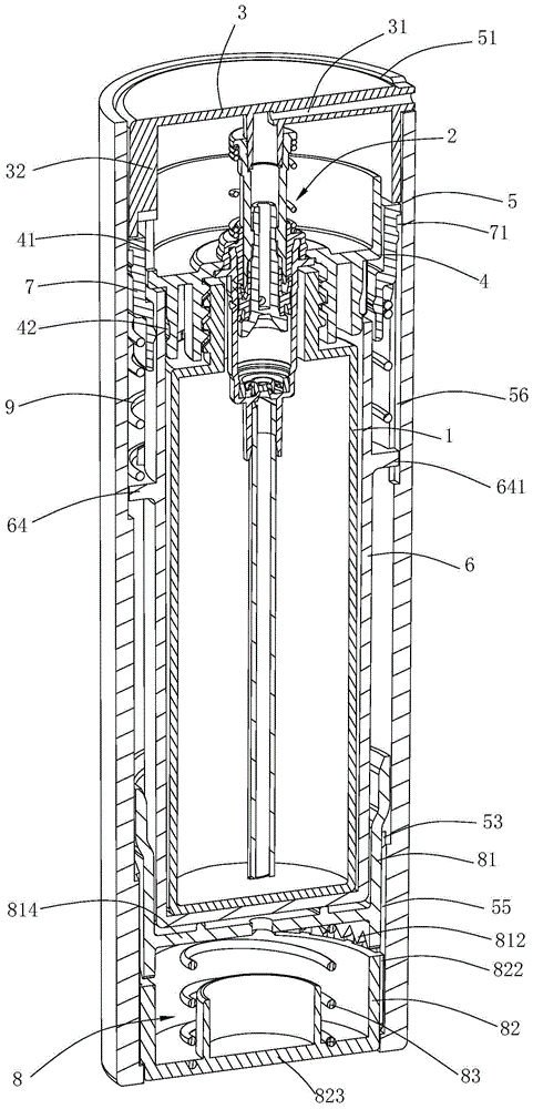
The invention relates to a cosmetic container, comprising an inner bottle body, a pump body assembly, a head cap, a collar, an outer bottle body, an inner sleeve, a clamping sleeve and an adjustment mechanism, wherein the adjustment mechanism can be moved up and down on the bottom of the outer bottle body, It is used to push the whole composed of the inner sleeve, the inner bottle body, the pump body assembly, the head cap and the collar up and down so that the head cap is exposed to the top opening of the outer bottle body or hidden in the outer bottle body. The head cap is a limiting structure for constraining the position of the inner sleeve when the top opening of the outer bottle body is exposed or hidden in the outer bottle body. In the present invention, the whole composed of the inner sleeve, the inner bottle body, the pump body assembly, the head cap and the collar can move up and down relative to the outer bottle body, and the upward movement makes the head cap expose the outer bottle body to open the container, and moves downward until the head cap is hidden The container is closed in the outer bottle body, which is convenient to use; when the head cap is exposed to the outer bottle body, the whole composed of the inner bottle body, the pump body assembly, the head cap and the collar is pulled out, which is convenient for replacing the inner bottle body and repeated use. Cosmetic container.
Description
技术领域technical field
本发明涉及一种化妆品容器。The present invention relates to a cosmetic container.
背景技术Background technique
在现有技术中,乳液泵广泛用于化妆品及沐浴用品,当需要使用时,按压按头,即可把需要的乳液取出,这种方法即方便又卫生。In the prior art, lotion pumps are widely used in cosmetics and bath products. When needed, the desired lotion can be taken out by pressing the head, which is convenient and hygienic.
授权公告号为CN203127397U的中国实用新型专利《一种新型乳液泵》(申请号:201320109153.0)披露了一种结构,其包括按头,按头套设于螺牙上端,按头底部与螺牙内部相对应设置有卡位,按头底部与螺牙上端设置的扣线相配合,螺牙内部设置有主柱,主柱顶端与按头内部相互倒角配合设置,主柱下方还设置有副柱,主柱和副柱之间设有弹簧,在螺牙下端套设有吸管。上述结构的乳液泵采用按头底部与螺牙内部卡位连接,按下按头旋转90度可切换开关,按头内部与主柱顶端相互倒角配合,按头上下活动时可产生吸力和泵液效果,在将按头锁定或解锁时泵的总高度发生变化,按头一旦打开就不能关闭,如果要关闭,就必须把头帽按压下去,而这样就会导致液体会从按头的出液孔流出。The Chinese utility model patent "A Novel Lotion Pump" (application number: 201320109153.0) with the authorization announcement number CN203127397U discloses a structure, which includes a pressing head, the pressing head is sleeved on the upper end of the screw teeth, and the bottom of the pressing head is in contact with the inside of the screw teeth. Correspondingly, there is a clamping position, the bottom of the pressing head is matched with the buckle line set at the upper end of the screw teeth, the main column is arranged inside the screw teeth, the top of the main column and the inside of the pressing head are arranged to cooperate with each other by chamfering each other, and a sub-column is also arranged below the main column. A spring is arranged between the main column and the auxiliary column, and a straw is sleeved at the lower end of the screw thread. The lotion pump of the above structure adopts the bottom of the press head to be connected with the internal clamping position of the screw teeth. Press the press head to rotate 90 degrees to switch the switch. The inside of the press head and the top of the main column are chamfered with each other. When the press head moves up and down, it can generate suction and pump. Liquid effect, the total height of the pump changes when the press head is locked or unlocked. Once the press head is opened, it cannot be closed. If it is to be closed, the head cap must be pressed down, which will cause the liquid to flow out of the press head. holes flow out.
另外,上述现有的乳液泵无法重复使用,在泵内物料使用完毕后一般就会作废,不仅导致消费者的使用成本较高,也造成了能源浪费。In addition, the above-mentioned existing lotion pump cannot be reused, and the materials in the pump are generally discarded after use, which not only leads to high usage costs for consumers, but also causes energy waste.
因此,对于目前带有泵头的化妆品容器,有待于做进一步的改进。Therefore, for the current cosmetic container with a pump head, further improvement is required.
发明内容SUMMARY OF THE INVENTION
本发明所要解决的第一个技术问题是针对现有技术的现状,提供一种便于更换内瓶从而降低使用成本、避免浪费的化妆品容器。The first technical problem to be solved by the present invention is to provide a cosmetic container that is easy to replace the inner bottle, thereby reducing the use cost and avoiding waste.
本发明所要解决的第二个技术问题是针对现有技术的现状,提供一种通过使整个泵体上下移动而实现开关的化妆品容器。The second technical problem to be solved by the present invention is to provide a cosmetic container that can be switched on and off by moving the entire pump body up and down, aiming at the current state of the prior art.
本发明解决上述技术问题所采用的技术方案为:一种化妆品容器,包括The technical scheme adopted by the present invention to solve the above technical problems is: a cosmetic container, comprising:
内瓶体,用于盛放流体;The inner bottle is used to hold the fluid;
泵体组件,设于所述内瓶体的上端口处且用于将内瓶体内的流体泵出;a pump body assembly, arranged at the upper port of the inner bottle body and used for pumping out the fluid in the inner bottle body;
头帽,连接于所述泵体组件的出液口处,具有供流体输出的喷嘴;a head cap, connected to the liquid outlet of the pump body assembly, and having a nozzle for fluid output;
其特征在于:还包括It is characterized in that it also includes
卡圈,套置在所述泵体组件的外周且与内瓶体的顶部脱卸式连接;a collar, sleeved on the outer periphery of the pump body assembly and detachably connected to the top of the inner bottle body;
外瓶体,具有顶部敞口;The outer bottle body has an open top;
内套,能上下移动地设于所述外瓶体中,所述内瓶体插置在该内套中,所述卡圈脱卸式连接在内套顶部并随内套上下移动;an inner sleeve, which can be moved up and down in the outer bottle body, the inner bottle body is inserted in the inner sleeve, and the collar is detachably connected to the top of the inner sleeve and moves up and down with the inner sleeve;
卡套,设于所述外瓶体中且位于上部,用于对所述内套上行的位置进行限位;以及a ferrule, which is arranged in the outer bottle body and located at the upper part, and is used to limit the position of the inner sleeve going upward; and
调节机构,能上下移动地设于所述外瓶体的底部,用于将所述内套、内瓶体、泵体组件、头帽、卡圈组成的整体上下推动从而使头帽露出外瓶体的顶部敞口或隐藏在外瓶体中,该调节机构还具有能在头帽露出外瓶体的顶部敞口或隐藏在外瓶体中状态下对内套位置进行约束的限位结构。An adjusting mechanism, which can be moved up and down at the bottom of the outer bottle, is used to push the whole of the inner sleeve, the inner bottle, the pump assembly, the head cap and the collar up and down so that the head cap is exposed to the outer bottle The top of the body is open or hidden in the outer bottle body, and the adjusting mechanism also has a limit structure that can constrain the position of the inner sleeve when the head cap is exposed from the top opening of the outer bottle body or hidden in the outer bottle body.
在上述方案中,所述调节机构包括旋转套及底座,所述旋转套能上下移动且周向转动地设于外瓶体中且托置在内套的底部,所述底座能上下移动地设于外瓶体的底部,所述外瓶体的内周壁上设置有多个竖向延伸的第一导向条,相邻两第一导向条之间形成第一导向槽,相应的,所述旋转套的外周壁上设置有能与该第一导向槽导向配合且在旋转套上下移动状态下限制其周向转动的第二导向条;In the above solution, the adjustment mechanism includes a rotating sleeve and a base, the rotating sleeve can be moved up and down and circumferentially rotatably provided in the outer bottle body and supported at the bottom of the inner sleeve, and the base can be moved up and down. At the bottom of the outer bottle body, a plurality of vertically extending first guide bars are arranged on the inner peripheral wall of the outer bottle body, and a first guide groove is formed between two adjacent first guide bars. The outer peripheral wall of the sleeve is provided with a second guide bar that can guide and cooperate with the first guide groove and restrict the circumferential rotation of the rotating sleeve when the rotating sleeve moves up and down;
所述底座的上端面设置有第一凸齿,对应的,所述旋转套的下端设置有与该第一凸齿相对布置的第二凸齿;所述第一导向条上端面的形成自下而上沿旋转套的反转方向延伸且呈Z形的第一斜面、第二斜面;The upper end surface of the base is provided with a first convex tooth, correspondingly, the lower end of the rotating sleeve is provided with a second convex tooth arranged opposite to the first convex tooth; the upper end surface of the first guide strip is formed from the bottom and the first inclined plane and the second inclined plane extending along the reversal direction of the rotating sleeve and in a Z shape;
在所述旋转套上下移动状态下,所述第一凸齿对应相邻两第二凸齿之间的齿间隙布置且向旋转套的转动方向偏移;在所述旋转套上移至第二导向条脱离第一导向槽状态下,所述旋转套随底座上移而转动从而使第二导向条与第一导向槽错位或对齐。When the rotating sleeve moves up and down, the first protruding teeth are arranged corresponding to the tooth gap between two adjacent second protruding teeth and are offset to the rotation direction of the rotating sleeve; When the guide bars are separated from the first guide grooves, the rotating sleeve rotates with the upward movement of the base, so that the second guide bars are misaligned or aligned with the first guide grooves.
上述结构用于驱动内套、内瓶体、泵体组件、头帽、卡圈组成的整体上下移动,从而实现化妆品容器的开关,这样的开关方式带动泵体组件整体上下移动,内瓶体中的气压在上下移动过程中不发生变化,从而避免了乳液浪费的问题。The above structure is used to drive the whole composed of the inner sleeve, the inner bottle body, the pump body assembly, the head cap and the collar to move up and down, so as to realize the opening and closing of the cosmetic container. The air pressure does not change during the up and down movement, thus avoiding the problem of waste of emulsion.
优选地,所述第二凸齿为若干个三角状结构且在旋转套的下端相互衔接,相邻两第二凸齿之间形成尖端朝上的三角状齿间隙,相应的,所述第一凸齿为能与该齿间隙相配合的三角状结构。该结构便于相互配合实现旋转套位置的限位,从而将化妆品容器保持在开或关的状态。Preferably, the second protruding teeth are a plurality of triangular structures and are connected to each other at the lower end of the rotating sleeve, and a triangular tooth gap with an upward tip is formed between two adjacent second protruding teeth. Correspondingly, the first The protruding teeth are triangular structures that can be matched with the tooth gaps. The structure is convenient to cooperate with each other to realize the limit of the position of the rotating sleeve, so as to keep the cosmetic container in the open or closed state.
优选地,所述底座的外周壁上设置有竖向延伸的第三导向条,相应的,所述外瓶体的内壁上设置有与该第三导向条导向配合的第二导向槽。该结构不仅可对底座上下移动地进行引导,而且在周向上对底座进行限位,防止其周向转动。Preferably, a vertically extending third guide strip is provided on the outer peripheral wall of the base, and correspondingly, the inner wall of the outer bottle body is provided with a second guide groove that guides and cooperates with the third guide strip. The structure can not only guide the base to move up and down, but also limit the position of the base in the circumferential direction to prevent it from rotating in the circumferential direction.
优选地,所述调节机构还包括第一弹性件,所述底座的底部具有底板,所述旋转套具有与内套底部相抵的托板,所述第一弹性件弹性压缩在底板与托板之间、使底座始终保持向下运动的趋势。本发明的底座相当于化妆品容器的开关件,上述结构可在底座完成开关动作后使其复位,使化妆品容器整体结构紧凑、美观。Preferably, the adjustment mechanism further includes a first elastic member, the bottom of the base has a bottom plate, the rotating sleeve has a support plate that is abutted against the bottom of the inner sleeve, the first elastic member is elastically compressed between the bottom plate and the support plate time, so that the base always maintains the downward movement trend. The base of the present invention is equivalent to the switch part of the cosmetic container, and the above-mentioned structure can reset the base after the switch action is completed, so that the overall structure of the cosmetic container is compact and beautiful.
优选地,所述卡圈下部的外周壁上设置有沿周向布置的第一卡槽,对应的,所述内套的内周壁上设置有与该第一卡槽弹性卡接的卡条。所述内套上开有自上端向下延伸的缺口,该缺口将所述内套上部分隔为至少两块弹性片,所述卡条设于该弹性片的内周壁上。在内套、内瓶体、泵体组件、头帽、卡圈组成的整体向上移动后,将内瓶体、泵体组件、头帽、卡圈组成的整体向上拉动,可使卡条与第一卡槽相互脱离,从而将其取出,便于更换内瓶体。Preferably, the outer peripheral wall of the lower part of the clamping ring is provided with a first clamping groove arranged in the circumferential direction, and correspondingly, the inner peripheral wall of the inner sleeve is provided with a clamping strip elastically clamped with the first clamping groove. The inner sleeve is provided with a notch extending downward from the upper end, the notch divides the upper part of the inner sleeve into at least two elastic sheets, and the clips are arranged on the inner peripheral wall of the elastic sheets. After the whole composed of the inner sleeve, the inner bottle body, the pump body assembly, the head cap and the clamp ring is moved upward, the whole composed of the inner bottle body, the pump body assembly, the head cap and the clamp ring is pulled upward, so that the clamp bar can be connected with the first part. A card slot is disengaged from each other, so that it can be taken out for easy replacement of the inner bottle body.
优选地,所述卡圈夹紧在泵体组件的外周且螺纹连接在内瓶体的顶部,所述泵体组件的下部插置在内瓶体中,所述泵体组件的上部位于卡圈上方。该结构便于更换内瓶体。Preferably, the collar is clamped on the outer circumference of the pump body assembly and is threadedly connected to the top of the inner bottle body, the lower part of the pump body assembly is inserted into the inner bottle body, and the upper part of the pump body assembly is located on the collar above. The structure is convenient to replace the inner bottle body.
为了便于使用,所述头帽连接在泵体组件上端,所述头帽的内周壁上设置有竖向延伸的第四导向条,所述卡圈上部开有与该第四导向条导向配合的第三导向槽。For ease of use, the head cap is connected to the upper end of the pump body assembly, the inner peripheral wall of the head cap is provided with a fourth guide strip extending vertically, and the upper part of the collar is provided with a guide for guiding and matching with the fourth guide strip. the third guide groove.
优选地,所述内套的外周壁上设置有托圈,该托圈的边缘凸设有导向块,对应的,所述外瓶体的内周壁上设置有与该导向块导向配合的第四导向槽,所述卡套与托圈之间设置有能使内套始终保持向下移动趋势的第二弹性件。该结构便于使内套、内瓶体、泵体组件、头帽、卡圈组成的整体向下移动至头帽完全隐藏在外瓶体中。Preferably, a support ring is provided on the outer peripheral wall of the inner sleeve, and a guide block is protruded from the edge of the support ring. Correspondingly, the inner peripheral wall of the outer bottle body is provided with a fourth guide block that guides and cooperates with the guide block. A guide groove, and a second elastic member is arranged between the ferrule and the support ring, which can keep the inner sleeve moving downwards all the time. The structure is convenient to move the whole composed of the inner sleeve, the inner bottle body, the pump body assembly, the head cap and the clip ring downward until the head cap is completely hidden in the outer bottle body.
与现有技术相比,本发明的优点在于:本发明内套、内瓶体、泵体组件、头帽、卡圈组成的整体可通过调节机构相对于外瓶体上下移动,向上移动使头帽露出外瓶体将容器打开,向下移动至头帽隐藏在外瓶体中将容器关闭,使用方便;在头帽露出于外瓶体状态下,可将内瓶体、泵体组件、头帽、卡圈组成的整体拉出,便于更换内瓶体,重复使用化妆品容器,从而降低使用成本、避免浪费。Compared with the prior art, the advantages of the present invention lie in that: the entire body composed of the inner sleeve, the inner bottle body, the pump body assembly, the head cap and the collar can be moved up and down relative to the outer bottle body through the adjusting mechanism, and the head can be moved upwards to make the head. The cap is exposed to the outer bottle body to open the container, and the container is closed by moving downward until the head cap is hidden in the outer bottle body, which is convenient to use; when the head cap is exposed to the outer bottle body, the inner bottle body, pump body components and head cap can be removed. , The whole composed of the collar is pulled out, which is convenient to replace the inner bottle body and reuse the cosmetic container, thereby reducing the use cost and avoiding waste.
附图说明Description of drawings
图1为本发明实施例的结构示意图(不使用状态);1 is a schematic structural diagram of an embodiment of the present invention (not in use);
图2为本发明实施例的结构示意图(使用状态);Fig. 2 is the structural schematic diagram (use state) of the embodiment of the present invention;
图3为图1的剖视图;Fig. 3 is the sectional view of Fig. 1;
图4为本发明实施例中外瓶体的剖视图;4 is a cross-sectional view of an outer bottle body in an embodiment of the present invention;
图5为本发明实施例中旋转套的结构示意图;5 is a schematic structural diagram of a rotating sleeve in an embodiment of the present invention;
图6为本发明实施例中底座的结构示意图;6 is a schematic structural diagram of a base in an embodiment of the present invention;
图7为本发明实施例中内套的结构示意图;Fig. 7 is the structural representation of the inner sleeve in the embodiment of the present invention;
图8为本发明实施例中第一凸齿与齿间隙的配合状态结构示意图。FIG. 8 is a schematic structural diagram of the matching state of the first protruding teeth and the tooth gap in the embodiment of the present invention.
具体实施方式Detailed ways
以下结合附图实施例对本发明作进一步详细描述。The present invention will be further described in detail below with reference to the embodiments of the accompanying drawings.
如图1~8所示,本实施例的化妆品容器包括内瓶体1、泵体组件2、头帽3、卡圈4、外瓶体5、内套6、卡套7及调节机构8,内瓶体1用于盛放流体,在本实施例中可进行替换。泵体组件2设于内瓶体1的上端口处且用于将内瓶体1内的流体泵出,该泵体组件2为用于化妆品容器中的常规泵体结构,在此不做赘述。头帽3连接于泵体组件2的出液口处,具有供流体输出的喷嘴31。As shown in FIGS. 1-8 , the cosmetic container of this embodiment includes an inner bottle body 1 , a pump body assembly 2 , a
上述卡圈4套置在泵体组件2的外周且与内瓶体1的顶部脱卸式连接。卡圈4夹紧在泵体组件2的外周且螺纹连接在内瓶体1的顶部,泵体组件2的下部插置在内瓶体1中,泵体组件2的上部位于卡圈4上方。头帽3连接在泵体组件2上端,头帽3的内周壁上设置有竖向延伸的第四导向条32,卡圈4上部开有与该第四导向条32导向配合的第三导向槽41。The above-mentioned collar 4 is sleeved on the outer periphery of the pump body assembly 2 and is detachably connected with the top of the inner bottle body 1 . The collar 4 is clamped on the outer circumference of the pump body assembly 2 and is screwed to the top of the inner bottle body 1 . The
上述外瓶体5具有顶部敞口51,内套6能上下移动地设于外瓶体5中,内瓶体5插置在该内套6中,卡圈4脱卸式连接在内套6顶部并随内套6上下移动。卡圈4下部的外周壁上设置有沿周向布置的第一卡槽42,对应的,内套6的内周壁上设置有与该第一卡槽42弹性卡接的卡条61。如图7所示,内套6上开有自上端向下延伸的缺口62,该缺口62将内套6上部分隔为至少两块弹性片63,卡条61设于该弹性片63的内周壁上。The above-mentioned
如图3所示,上述卡套7设于外瓶体5中且位于上部,用于对内套6上行的位置进行限位。卡套7的外周壁上开有环形槽71,对应的,所述外瓶体5的内周壁上设置有与该环形槽71相卡接的凸圈52。在头帽3隐藏在外瓶体5中时,头帽3的下端与该卡套7上端相抵、头帽3上端面与外瓶体5的上边缘大致齐平。As shown in FIG. 3 , the above-mentioned
本实施例的调节机构8能上下移动地设于外瓶体5的底部,用于将内套6、内瓶体5、泵体组件2、头帽3、卡圈4组成的整体上下推动从而使头帽3露出外瓶体5的顶部敞口51或隐藏在外瓶体5中,该调节机构8还具有能在头帽3露出外瓶体5的顶部敞口51或隐藏在外瓶体5中状态下对内套6位置进行约束的限位结构。The
具体的,如图3~6所示,上述调节机构8包括旋转套81、底座82及第一弹性件83,旋转套81能上下移动且周向转动地设于外瓶体5中且托置在内套6的底部,底座82能上下移动地设于外瓶体5的底部,外瓶体5的内周壁上设置有多个竖向延伸的第一导向条53,相邻两第一导向条53之间形成第一导向槽54,相应的,旋转套81的外周壁上设置有能与该第一导向槽54导向配合且在旋转套81上下移动状态下限制其周向转动的第二导向条811。底座82的上端面设置有第一凸齿821,对应的,旋转套81的下端设置有与该第一凸齿821相对布置的第二凸齿812;第一导向条53上端面的形成自下而上沿旋转套81的反转方向延伸且呈Z形的第一斜面531a、第二斜面531b,且该第一斜面531a、第二斜面531b上端的高度大致相等。在旋转套81上下移动状态下,第一凸齿821对应相邻两第二凸齿812之间的齿间隙813布置且向旋转套81的转动方向偏移;在旋转套81上移至第二导向条811脱离第一导向槽54状态下,旋转套81随底座82上移而转动从而使第二导向条811与第一导向槽54错位或对齐。第二凸齿812为若干个三角状结构且在旋转套81的下端相互衔接,相邻两第二凸齿812之间形成尖端朝上的三角状齿间隙813,第一凸齿821有四个且间隔分布在底座82的上端面上,第一凸齿821为能与该齿间隙813相配合的三角状结构。底座82的底部具有底板823,旋转套81具有与内套6底部相抵的托板814,第一弹性件83为弹簧,弹性压缩在底板823与托板814之间、使底座82始终保持向下运动的趋势。Specifically, as shown in FIGS. 3 to 6 , the above-mentioned
在本实施例中,底座82的外周壁上设置有竖向延伸的第三导向条822,相应的,外瓶体5的内壁上设置有与该第三导向条822导向配合的第二导向槽55。该结构不仅可对底座82上下移动地进行引导,而且在周向上对底座82进行限位,防止其周向转动。内套6的外周壁上设置有托圈64,该托圈64的边缘凸设有导向块641,对应的,外瓶体5的内周壁上设置有与该导向块641导向配合的第四导向槽56,卡套7与托圈64之间设置有能使内套6始终保持向下移动趋势的第二弹性件9,该第二弹性件9为弹簧。In this embodiment, a
本实施例的底座82相当于化妆品容器的开关件,使用本实施例的化妆品容器,在头帽3完全隐藏在内瓶体5中的状态下,第二导向条811与第一导向槽54相互配合,如图8所示,仅第一凸齿821的上部位于齿间隙813中且偏执在该齿间隙813的一侧;用手推动底座82向上移动,从而推动内套6、内瓶体5、泵体组件2、头帽3、卡圈4组成的整体向上移动,由于此时底座82、旋转套81仅能上下移动,因此,第一凸齿821与齿间隙813的配合位置保持不变;当旋转套81的下端对应第一导向条53上端时,第二导向条811脱出第一导向槽54,此时,底座82继续上移,第一凸齿821与齿间隙813的配合位置发生变化,第一凸齿821逐渐卡入齿间隙813中并带动旋转套81逆时针转动,当第一凸齿821完全卡入齿间隙813中后,不再带动旋转套81周向转动,此时,松开底座82,底座82在第一弹性件83作用下向下复位,而第二导向条811的下端与第一导向条53上端的第一斜面531a相抵,并在第二弹性件9的弹力与第一斜面531a的导向作用下,使旋转套81继续逆时针转动半个齿间隙813的距离,此时,第二导向条811的下端抵靠在第一斜面531a下端与第一导向条53形成的限位槽532中,从而使旋转套81不会向下移动,对内套6、内瓶体5、泵体组件2、头帽3、卡圈4组成的整体位置进行限位,此时,头帽3露出于外瓶体5外,化妆品容器处于打开状态,按压头帽3可使用;The
并且,在该状态下,可将内瓶体5、泵体组件2、头帽3、卡圈4组成的整体向上拉动,可使卡条61与第一卡槽42相互脱离,从而将其取出,将内瓶体1自卡圈4上拧下,可进行更换;In addition, in this state, the whole composed of the
在不使用化妆品时,向上抵压底座82,底座82上端的第一凸齿821逐渐卡入齿间隙813中带动旋转套81转动,当第一凸齿821完全卡入齿间隙813中后,不再带动旋转套81周向转动,此时,松开底座82,直至第二导向条811的下端与第一导向条53上端的第二斜面531b相抵,并在第二弹性件9的弹力与第二斜面531b的导向作用下,使旋转套81继续逆时针转动半个齿间隙813的距离,此时,第二导向条811的下端与第一导向槽54对齐,内套6、内瓶体5、泵体组件2、头帽3、卡圈4组成的整体在第二弹性件9的作用下向下运动至头帽3完全隐藏在外瓶体5中。When the cosmetics are not in use, press the base 82 upward, and the first protruding
Claims (10)
Priority Applications (1)
| Application Number | Priority Date | Filing Date | Title |
|---|---|---|---|
| CN202010290513.6A CN111572943B (en) | 2020-04-14 | 2020-04-14 | A cosmetic container |
Applications Claiming Priority (1)
| Application Number | Priority Date | Filing Date | Title |
|---|---|---|---|
| CN202010290513.6A CN111572943B (en) | 2020-04-14 | 2020-04-14 | A cosmetic container |
Publications (2)
| Publication Number | Publication Date |
|---|---|
| CN111572943A true CN111572943A (en) | 2020-08-25 |
| CN111572943B CN111572943B (en) | 2025-05-02 |
Family
ID=72118791
Family Applications (1)
| Application Number | Title | Priority Date | Filing Date |
|---|---|---|---|
| CN202010290513.6A Active CN111572943B (en) | 2020-04-14 | 2020-04-14 | A cosmetic container |
Country Status (1)
| Country | Link |
|---|---|
| CN (1) | CN111572943B (en) |
Citations (7)
| Publication number | Priority date | Publication date | Assignee | Title |
|---|---|---|---|---|
| US5399040A (en) * | 1993-07-06 | 1995-03-21 | Risdon Corporation | Dispenser with replaceable cosmetic holder |
| WO2012161408A1 (en) * | 2011-05-24 | 2012-11-29 | (주)톨리코리아 | Airless-pump cosmetics container having a retractable operating button |
| KR200475334Y1 (en) * | 2014-07-04 | 2014-12-04 | (주)민진 | A cosmetic vessel capable of refill |
| CN203986621U (en) * | 2014-03-28 | 2014-12-10 | 上海竹本容器包装有限公司 | A kind of used for cosmetic is replaced packaging container |
| KR101912115B1 (en) * | 2017-08-28 | 2018-10-29 | (주)아모레퍼시픽 | cosmetic tool |
| CN110662455A (en) * | 2017-05-04 | 2020-01-07 | 申东勋 | Push type cosmetic container capable of bidirectional operation |
| CN212638301U (en) * | 2020-04-14 | 2021-03-02 | 浙江晟祺实业有限公司 | a cosmetic container |
-
2020
- 2020-04-14 CN CN202010290513.6A patent/CN111572943B/en active Active
Patent Citations (7)
| Publication number | Priority date | Publication date | Assignee | Title |
|---|---|---|---|---|
| US5399040A (en) * | 1993-07-06 | 1995-03-21 | Risdon Corporation | Dispenser with replaceable cosmetic holder |
| WO2012161408A1 (en) * | 2011-05-24 | 2012-11-29 | (주)톨리코리아 | Airless-pump cosmetics container having a retractable operating button |
| CN203986621U (en) * | 2014-03-28 | 2014-12-10 | 上海竹本容器包装有限公司 | A kind of used for cosmetic is replaced packaging container |
| KR200475334Y1 (en) * | 2014-07-04 | 2014-12-04 | (주)민진 | A cosmetic vessel capable of refill |
| CN110662455A (en) * | 2017-05-04 | 2020-01-07 | 申东勋 | Push type cosmetic container capable of bidirectional operation |
| KR101912115B1 (en) * | 2017-08-28 | 2018-10-29 | (주)아모레퍼시픽 | cosmetic tool |
| CN212638301U (en) * | 2020-04-14 | 2021-03-02 | 浙江晟祺实业有限公司 | a cosmetic container |
Also Published As
| Publication number | Publication date |
|---|---|
| CN111572943B (en) | 2025-05-02 |
Similar Documents
| Publication | Publication Date | Title |
|---|---|---|
| TWI225023B (en) | Pump with function of measuring fixed amount | |
| DE60315926D1 (en) | Discharge pump for media | |
| WO2019119527A1 (en) | Novel spray head | |
| CN210144393U (en) | A suction cup cover and a thermos cup with a suction cup cover | |
| WO2022156007A1 (en) | Liquid pump | |
| US10492586B2 (en) | Material dispenser/applicator | |
| KR20130130569A (en) | Cosmetics container of nozzle type | |
| CN110723408A (en) | Novel full-plastic emulsion pump structure | |
| CN107934182A (en) | A kind of new type nozzle | |
| CN217089872U (en) | A paste bottle with a multi-stage push-out mechanism | |
| CN212638301U (en) | a cosmetic container | |
| CN102069051A (en) | Lotion pump | |
| CN111572943B (en) | A cosmetic container | |
| CN110169644B (en) | Middle bundle device of cosmetic storage container | |
| KR20120111540A (en) | Vessel for liquid cosmetics | |
| JP2005193907A (en) | Mouth solidification prevention jig and container with mouth solidification prevention jig | |
| CN211767501U (en) | Emulsion pump provided with elastic sleeve body | |
| CN209852890U (en) | An environmentally friendly lotion pump | |
| CN201900069U (en) | Lotion pump | |
| JP2013500912A (en) | Cosmetic mechanism | |
| CN218618051U (en) | Self-rotating locking and unlocking pressing pump | |
| CN217416745U (en) | Replaceable vacuum cream bottle | |
| CN109171397A (en) | A kind of bottle cap and cup | |
| CN116946558A (en) | All-plastic combined pressing pump | |
| CN209905444U (en) | Spray head |
Legal Events
| Date | Code | Title | Description |
|---|---|---|---|
| PB01 | Publication | ||
| PB01 | Publication | ||
| SE01 | Entry into force of request for substantive examination | ||
| SE01 | Entry into force of request for substantive examination | ||
| GR01 | Patent grant | ||
| GR01 | Patent grant |