Disclosure of Invention
Technical problem to be solved
The invention provides a glass fiber reinforced plastic storage tank forming processing machine tool, which can solve the following problems in the processing process of a glass fiber reinforced plastic storage tank; the existing equipment of a can only be processed to the glass steel storage tank of a certain diameter or length in the course of working, needs different machine-shaping equipment to the glass steel storage tank of different specifications, and the cost is higher, and in the existing equipment of b, can only carry out the outer centre gripping of single-point through the mode of outside centre gripping to the glass steel storage tank, lead to the glass steel storage tank stability not high appearing in the course of working, easily take place the shake scheduling problem.
(II) technical scheme
In order to achieve the purpose, the invention adopts the following technical scheme: a glass fiber reinforced plastic storage tank forming processing machine tool comprises a rotating rack, a placing rack, a movable clamping mechanism, a fixed clamping mechanism and an inner supporting mechanism, wherein the placing rack is arranged on the lower end face of the rotating rack, and the movable clamping mechanism, the inner supporting mechanism and the fixed clamping mechanism are sequentially arranged on the rotating rack from left to right; wherein:
remove fixture including centre gripping locking branch chain, removal frame, expanding spring, fixed long slab, cylinder, removal rectangular block and angle bar, wherein removal frame install on removing the rectangular block through sliding fit, centre gripping locking branch chain circumference is installed on removing the frame, fixed long slab welding is in removing the rectangular block left side, and fixed long slab and remove between the frame through expanding spring be connected No. one, a cylinder is installed on interior supporting mechanism, and a cylinder is connected with removal rectangular block right-hand member face, remove rectangular block right side circumference and install the angle bar, and interior supporting mechanism has seted up No. two spouts, the angle bar passes through No. two spout sliding fit with interior supporting mechanism.
Centre gripping locking branch including the centre gripping subassembly on one number, centre gripping subassembly, locking Assembly, rotating electrical machines and cam piece down, wherein removal frame from the left hand right side seted up a hole, No. two holes in proper order, No. one go up centre gripping subassembly lower extreme and pass No. two hole slidable mounting on removing the frame inner wall, No. one go up the centre gripping subassembly and seted up No. three spouts, No. one down centre gripping subassembly and No. one go up the centre gripping subassembly through No. three spout slidable connection, and No. one down centre gripping subassembly passes through the telescopic spring pole with No. one last centre gripping subassembly and is connected, locking Assembly passes No. two hole slidable mounting on removing the frame inner wall, No. two rotating electrical machines install on one last centre gripping subassembly, No. two motor output shafts are connected with the cam piece pivot through the axle sleeve, the cam piece upper end supports and leans on No. one down centre gripping subassembly, the cam piece lower extreme supports and leans on locking Assembly.
A go up the centre gripping subassembly include centre gripping rectangular plate, a spring beam, a fixed block, trapezoidal piece and No. two cylinders, wherein last centre gripping rectangular plate pass a hole slidable mounting inside removing the frame, a fixed block welding is on last centre gripping rectangular plate, a spring beam upper end is connected on removing frame top inner wall, a spring beam lower extreme is connected on a fixed block, go up centre gripping rectangular plate and remove the frame inner wall and be connected through a spring beam, remove frame below inner wall and seted up No. four spouts, No. two cylinders are installed on removing frame right side inner wall, trapezoidal piece and removal frame are through No. four spout sliding fit, trapezoidal piece left end is supported and is leaned on last centre gripping rectangular plate lower extreme, the trapezoidal piece right-hand member is connected with No. two cylinders.
The first lower clamping assembly comprises a lower clamping long plate, a second fixed block, a movable short plate, a second spring sliding rod, a third spring sliding rod, a second expansion spring and a trapezoid long block, wherein a T-shaped groove, a fifth sliding groove and a sixth sliding groove are sequentially formed in the lower clamping long plate from right to left, the T-shaped groove, the fifth sliding groove and the sixth sliding groove are communicated, the sixth sliding groove penetrates through the front side and the rear side of the lower clamping long plate, the second fixed block is fixedly arranged at the lower end of the left side of the lower clamping long plate, the lower end of the second fixed block abuts against a cam block, the second spring sliding rod is arranged in the middle of the T-shaped groove, the movable short plate is arranged at the upper end of the second spring sliding rod, a triangle block is arranged at the lower end of the second spring sliding rod, the third spring sliding rod is arranged in the fifth sliding groove, the right side of the third spring sliding rod abuts against the triangle block, the trapezoid long block is movably arranged in the sixth sliding groove through the second expansion spring, the left side of the third spring sliding rod is abutted against the trapezoid long block, and first grooves matched with the sixth sliding grooves are uniformly distributed on the inner wall of the upper clamping long plate.
The inner supporting mechanism comprises a supporting frame, a third air cylinder, a fifth spring rod, a third fixing block, a lifting cam component and a locking cam component, wherein the supporting frame is circumferentially arranged on the end surface of the rotating frame, a U-shaped groove is arranged at the lower end of the supporting frame, three fixing blocks are symmetrically arranged at the left side and the right side below the supporting frame, the three fixing blocks are connected with the inner wall of the rotating frame through a fifth spring rod, a hole is arranged at the right side of the rotating frame, the supporting frame penetrates through the hole and is matched with the locking cam component through the U-shaped groove, the lower end surface of the support frame is abutted against the lifting cam assembly, the left end surface of the rotating rack is provided with a first through groove, the support frame passes through the first through groove and is matched with the locking cam assembly through a U-shaped groove, and the lower end face of the support frame is abutted against the lifting cam component, the third cylinder is installed on the inner wall of the rotating rack, and the right side of the third cylinder is connected with the left support frame.
Preferably, the rotation frame including L template, electronic slider, a rotating electrical machines, axis of rotation and square hole post, wherein L template below inner wall on seted up a spout, through a spout sliding connection between electronic slider and the L template, the square hole post passes through the bearing and installs on electronic slider left side inner wall, a rotating electrical machines installs on L template right side outer wall, a cavity has been seted up to the axis of rotation, axis of rotation one end is passed through the bearing and is installed on L template right side inner wall, and the axis of rotation passes through the axle sleeve with a rotating electrical machines and rotate and be connected, the axis of rotation other end cooperatees with the square hole post.
Preferably, the rack including lift cylinder, bottom plate, a live-rollers, triangular prism and supporting shoe, wherein the lift cylinder install in rotating the frame, the bottom plate is installed to lift cylinder top, the triangular prism is installed to the symmetry around the bottom plate, evenly be fixed with the supporting shoe on the triangular prism inclined plane, the live-rollers bilateral symmetry passes through the bearing and installs on the supporting shoe, the bottom plate intermediate position is seted up slottedly, the inslot evenly is fixed with the supporting shoe, the live-rollers bilateral symmetry passes through the bearing and installs on the supporting shoe.
Preferably, locking Assembly include No. four spring levers, wherein No. four spring levers through a hole slidable mounting on removing frame left side inner wall, and remove the rectangle piece and evenly seted up No. two recesses, No. four spring lever upper end is passed a hole and is leaned on the cam piece, No. four spring lever lower extreme and No. two recess cooperations.
Preferably, the lift cam subassembly include No. three rotating electrical machines, a camshaft and a cake, wherein No. three rotating electrical machines install on rotating frame left side inner wall, and No. three rotating electrical machines output shafts are connected with a camshaft through the axle sleeve, a cake and a camshaft coaxial line, and install on rotating frame right side inner wall, a camshaft passes through bearing and a cake normal running fit, No. two cavitys have been seted up to camshaft inside, the locking cam subassembly is installed inside a camshaft, and No. two logical grooves have all been seted up to camshaft circumference.
Preferably, locking cam subassembly including No. four rotating electrical machines, No. two camshafts, No. two circle pieces and control rectangular board, wherein No. four rotating electrical machines install on camshaft right side inner wall, and No. four rotating electrical machines output shaft is connected with No. two camshafts through the axle sleeve, No. two circle pieces and No. two camshaft coaxial lines, and install on camshaft left side inner wall, No. two camshafts pass through bearing and No. two circle piece normal running fit, the control rectangular board supports and leans on No. two camshafts through No. two logical grooves.
Preferably, fixed fixture including No. four cylinders, fixed frame, No. two go up centre gripping subassembly and No. two lower centre gripping subassemblies, wherein fixed frame right side seted up No. three holes, No. two go up the centre gripping subassembly and pass No. three hole slidable mounting inside fixed frame, No. two lower centre gripping subassemblies and No. two last centre gripping subassembly sliding fit, No. four cylinders are installed in No. two last centre gripping subassemblies left sides, No. four cylinder tops and No. two lower centre gripping subassemblies are connected, No. two go up centre gripping subassembly and No. one go up centre gripping subassembly major structure the same, No. two lower centre gripping subassemblies are the same with a lower centre gripping subassembly major structure.
(III) advantageous effects
1. The invention provides a glass fiber reinforced plastic storage tank forming and processing machine tool, which can solve the following problems in the processing process of a glass fiber reinforced plastic storage tank; the existing equipment of a can only be processed to the glass steel storage tank of a certain diameter or length in the course of working, and the machine-shaping equipment that needs the difference to the glass steel storage tank of different specifications, the cost is great, and in the existing equipment of b, can only carry out single-point outer centre gripping to the glass steel storage tank through the mode of outside centre gripping, lead to the glass steel storage tank stability not high appearing in the course of working, easily take place the shake scheduling problem.
2. In the moving clamping mechanism designed by the invention, in the operation process, the first air cylinder drives the clamping and locking branched chain to move left and right through the first expansion spring, so that glass fiber reinforced plastic storage tanks with different lengths can be clamped, and the clamping and locking branched chain can be used for clamping glass fiber reinforced plastic storage tanks with different diameters through the cooperation of the first upper clamping assembly and the first lower clamping assembly.
3. In the operation process of the inner support mechanism designed by the invention, the third cylinder drives the left support frame to move left and right, so that multi-point inner support can be performed on glass fiber reinforced plastic storage tanks with different lengths, the glass fiber reinforced plastic storage tanks with different diameters can be internally supported in a manner of matching the lifting cam assembly and the locking cam assembly, and the stability of the glass fiber reinforced plastic storage tanks in the operation process is improved.
Detailed Description
The embodiments of the invention will be described in detail below with reference to the drawings, but the invention can be implemented in many different ways as defined and covered by the claims.
As shown in fig. 1 to 6, a machine tool for forming and processing a glass fiber reinforced plastic storage tank comprises a rotating frame 1, a placing frame 2, a movable clamping mechanism 3, a fixed clamping mechanism 4 and an inner support mechanism 5, wherein the placing frame 2 is installed on the lower end face of the rotating frame 1, and the movable clamping mechanism 3, the inner support mechanism 5 and the fixed clamping mechanism 4 are sequentially installed on the rotating frame 1 from left to right;
the rotating rack 1 comprises an L-shaped plate 11, an electric slider 12, a first rotating motor 13, a rotating shaft 14 and a square hole column 15, wherein a first sliding groove is formed in the inner wall below the L-shaped plate 11, the electric slider 12 is in sliding connection with the L-shaped plate 11 through the first sliding groove, the square hole column 15 is installed on the inner wall on the left side of the electric slider 12 through a bearing, the first rotating motor 13 is installed on the outer wall on the right side of the L-shaped plate 11, a first cavity is formed in the rotating shaft 14, one end of the rotating shaft 14 is installed on the inner wall on the right side of the L-shaped plate 11 through the bearing, the rotating shaft 14 is in rotating connection with the first rotating motor 13 through a shaft sleeve, the other end of the rotating shaft 14 is matched with the square hole column 15, during specific work, the electric slider 12 moves left and right on the L-shaped plate 11 through the first sliding groove, the electric slider 12 drives the glass fiber reinforced plastic storage tank on the placement rack 2 to move left and right to a working position, no. one rotating electrical machines 13 drive axis of rotation 14 is rotatory, and electric slider 12 left side intermediate position installs square hole post 15 through the bearing, and square hole post 15 cooperates with the square piece of the setting of axis of rotation 14 leftmost end, increases the stability of axis of rotation 14 in the course of the work.
The placing frame 2 comprises a lifting cylinder 21, a bottom plate 22, a first rotating roller 23, a triangular column 24 and a supporting block 25, wherein the lifting cylinder 21 is arranged on the rotating frame 1, the bottom plate 22 is arranged above the lifting cylinder 21, the triangular columns 24 are symmetrically arranged at the front and the back of the bottom plate 22, the supporting blocks 25 are uniformly fixed on the inclined planes of the triangular columns 24, the first rotating roller 23 is bilaterally and symmetrically arranged on the supporting blocks 25 through the bearings, the middle position of the bottom plate 22 is provided with a groove, the supporting blocks 25 are uniformly fixed in the groove, the first rotating roller 23 is bilaterally and symmetrically arranged on the supporting blocks 25 through the bearings, when in specific work, the first rotating roller 23 is provided with a glass fiber reinforced plastic storage tank, the lifting cylinder 21 is started, the lifting cylinder 21 pushes the bottom plate 22 to move upwards to convey the glass fiber reinforced plastic storage tank to a working position, and the first rotating roller 23 plays a certain supporting role in the rotating process of the glass fiber reinforced plastic storage tank.
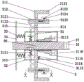
The movable clamping mechanism 3 comprises a clamping and locking branched chain 31, a movable frame 32, a first expansion spring 33, a fixed long plate 34, a first air cylinder 35, a movable rectangular block 36 and angle iron 37, wherein the movable frame 32 is arranged on the movable rectangular block 36 in a sliding fit mode, the clamping and locking branched chain 31 is circumferentially arranged on the movable frame 32, the fixed long plate 34 is welded on the left side of the movable rectangular block 36, the fixed long plate 34 is connected with the movable frame 32 through the first expansion spring 33, the first air cylinder 35 is arranged on the inner supporting mechanism 5, the first air cylinder 35 is connected with the right end face of the movable rectangular block 36, the angle iron 37 is circumferentially fixed on the right side of the movable rectangular block 36, the inner supporting mechanism 5 is provided with a second sliding groove, the angle iron 37 is in sliding fit with the inner supporting mechanism 5 through the second sliding groove, during specific work, the first air cylinder 35 is started, the first air cylinder 35 drives the movable rectangular block 36 to move, fixed long slab 34 passes through expanding spring 33 and drives the removal frame 32 and slide, drives centre gripping locking branch chain 31 to operating position, and angle bar 37 passes through No. two spouts and support 5 sliding fit in, makes and removes fixture 3 and be difficult for taking place the shake, has improved the stability in the working process.
The clamping and locking branched chain 31 comprises a first upper clamping component 311, a first lower clamping component 312, a locking component 313, a second rotating motor 314 and a cam block 315, wherein the moving frame 32 is sequentially provided with a first hole and a second hole from left to right, the lower end of the first upper clamping component 311 passes through the second hole and is slidably mounted on the inner wall of the moving frame 32, the first upper clamping component 311 is provided with a third sliding groove, the first lower clamping component 312 is slidably connected with the first upper clamping component 311 through the third sliding groove, the first lower clamping component 312 is connected with the first upper clamping component 311 through a telescopic spring rod, the locking component 313 passes through the second hole and is slidably mounted on the inner wall of the moving frame 32, the second rotating motor 314 is mounted on the first upper clamping component 311, the second motor output shaft is connected with the cam block 315 through a shaft sleeve, the upper end of the cam block 315 is abutted against the first lower clamping component 312, the lower end of the cam block 315 abuts against the locking component 313, during specific work, the first upper clamping component 311 moves outwards, the second rotating motor 314 drives the cam block 315 to rotate, the upper side of the cam block 315 pushes the first lower clamping component 312 to move outwards, the first lower clamping component 312 clamps the glass fiber reinforced plastic storage tank through matching with the first upper clamping component 311, due to the staggered special structure of the cam block 315, after the cam block 315 pushes the first lower clamping component 312 to a working position, the cam block 315 continues to rotate, but the first lower clamping component 312 cannot continue to move, the cam block 315 only pushes the locking component 313 to move inwards, the movable clamping mechanism 3 and the movable rectangular block 36 are locked, and the movable clamping mechanism 3 is fixed in the rotating process.
The first upper clamping assembly 311 includes an upper clamping long plate 3111, a first spring bar 3113, a first fixing block 3114, a trapezoid 3115 and a second cylinder 3116, wherein the upper clamping long plate 3111 passes through a first hole and is slidably mounted inside the moving frame 32, the first fixing block 3114 is welded on the upper clamping long plate 3111, the upper end of the first spring bar 3113 is connected to the inner wall above the moving frame 32, the lower end of the first spring bar 3113 is connected to the first fixing block 3114, the upper clamping long plate 3111 is connected to the inner wall of the moving frame 32 through the first spring bar 3113, a fourth sliding groove is formed in the inner wall below the moving frame 32, the second cylinder 3116 is mounted on the inner wall on the right side of the moving frame 32, the trapezoid 3115 is slidably matched with the moving frame 32 through the fourth sliding groove, the left end of the trapezoid 3115 abuts against the lower end of the upper clamping long plate 3111, the right end of the trapezoid 3115 is connected to the second cylinder 3116, and when the first cylinder 3116 is in operation, the trapezoid 3115 drives the trapezoid 3115 to move, wherein seted up the echelonment structure on trapezoidal piece 3115 inclined plane, when trapezoidal piece 3115 removed, the long board 3111 of centre gripping upwards removed in the extrusion of trapezoidal piece 3115, the ladder structure of trapezoidal piece 3115 makes and goes up the long board 3111 of centre gripping and stretch out the part length adjustable that removes frame 32, can carry out the centre gripping to the glass steel storage tank that the diameter is different, after the centre gripping, the initial position is got back to trapezoidal piece 3115 under No. two cylinder 3116 drives, upward the long board 3111 of centre gripping inwards moves back to the initial position under a spring-loaded stock 3113 drives.
The first lower clamping assembly 312 comprises a lower clamping long plate 3121, a second fixed block 3122, a movable short plate 3123, a second spring sliding rod 3124, a third spring sliding rod 3125, a second telescopic spring 3126 and a trapezoid long block 3127, wherein the lower clamping long plate 3121 is sequentially provided with a T-shaped groove, a fifth sliding groove and a sixth sliding groove from right to left, the T-shaped groove, the fifth sliding groove and the sixth sliding groove are communicated, the sixth sliding groove penetrates through the front and rear sides of the lower clamping long plate 3121, the second fixed block 3122 is fixedly installed at the lower end of the left side of the lower clamping long plate 3121, the lower end of the second fixed block 3122 is abutted against the cam block 315, the second spring sliding rod 3124 is installed at the middle position of the T-shaped groove, the upper end of the second spring sliding rod 3124 is installed with the movable short plate 3123, the lower end of the second spring sliding rod 3124 is provided with a triangle block, the third spring sliding rod 3125 is installed in the fifth sliding groove, and the right side of the third spring sliding rod 3125 is abutted against the triangle block, a trapezoid long block 3127 is movably arranged in the No. six sliding chute through a No. two expansion spring 3126, the left side of a No. three spring sliding rod 3125 is abutted against the trapezoid long block 3127, a No. one groove matched with the No. six sliding chute is uniformly distributed on the inner wall of the upper clamping long plate 3111, when the device works specifically, the No. two rotating motor 314 drives the cam block 315 to rotate, the cam block 315 abuts against the No. two fixing block 3122 and moves upwards, the lower clamping long plate 3121 moves upwards in the No. three sliding chute, when the lower clamping long plate 3121 moves to the working position, the movable short plate 3123 abuts against the inner wall of the glass fiber reinforced plastic storage tank and extrudes the No. two spring sliding rod 3124 to move downwards, a triangle block on the No. two spring sliding rod 3124 pushes the No. three spring sliding rod 3125 to move leftwards, the trapezoid long block 3127 is pushed to slide to the front side and the back side, the trapezoid long block 3127 is finally matched with the No. one groove, so as to realize the locking of the No. one lower clamping assembly 312 and the No. one upper clamping assembly 311, the inner wall and the outer wall of the glass fiber reinforced plastic storage tank are clamped.
The locking assembly 313 includes a four-gauge pogo stick 3131, wherein the four-gauge pogo stick 3131 is slidably mounted on the left inner wall of the moving frame 32 through a one-gauge hole, and the moving rectangular block 36 is uniformly provided with a second groove, the upper end of the fourth spring rod 3131 passes through the first hole and abuts against the cam block 315, the lower end of the fourth spring rod 3131 is matched with the second groove, when the clamping and locking branched chain 31 moves to the working position during the specific work, the cam block 315 continues to rotate, due to the staggered special structure of the cam blocks 315, the clamping and locking branched chain 31 cannot move when the cam blocks 315 continue to rotate, the cam blocks 315 only push the four-number spring rod 3131 to move inwards, and the lower end of the four-number spring rod 3131 is inserted into the second groove to fixedly lock the clamping and locking branched chain 31 and the movable rectangular block 36 in the downward movement process of the four-number spring rod 3131, so that the sliding in the rotation process is avoided.
Fixed fixture 4 including No. four cylinders 43, fixed frame 44, No. two go up centre gripping subassembly 41 and No. two lower centre gripping subassemblies 42, wherein fixed frame 44 right side seted up No. three holes, No. two go up centre gripping subassembly 41 and pass No. three hole slidable mounting inside fixed frame 44, No. two lower centre gripping subassembly 42 and No. two go up centre gripping subassembly 41 sliding fit, No. four cylinders 43 install in No. two last centre gripping subassemblies 41 left sides, No. four cylinder 43 top is connected with No. two lower centre gripping subassemblies 42, No. two go up centre gripping subassembly 41 and No. one go up centre gripping subassembly 311 major structure the same, No. two lower centre gripping subassembly 42 and No. one lower centre gripping subassembly 312 major structure the same, during concrete work, No. two go up centre gripping subassembly 41 and No. two lower centre gripping subassembly 42 theory of operation roughly the same, only distinguish is: the fourth cylinder 43 drives the second lower clamping assembly 42 to move inside and outside, and the first lower clamping assembly 312 is realized by driving a cam block 315 through a second rotating motor 314.
The inner support mechanism 5 comprises a support frame 51, a third air cylinder 52, a fifth spring rod 53, a third fixing block 54, a lifting cam assembly 55 and a locking cam assembly 56, wherein the support frame 51 is circumferentially arranged on the end surface of the rotating rack 1, a U-shaped groove is formed in the lower end of the support frame 51, the third fixing block 54 is symmetrically arranged on the left side and the right side below the support frame 51, the third fixing block 54 is connected with the inner wall of the rotating rack 1 through the fifth spring rod 53, a hole is formed in the right side of the rotating rack 1, the support frame 51 penetrates through the hole and is matched with the locking cam assembly 56 through the U-shaped groove, the lower end surface of the support frame 51 abuts against the lifting cam assembly 55, a first through groove is formed in the left end surface of the rotating rack 1, the support frame 51 penetrates through the first through groove and is matched with the locking cam assembly 56 through the U-shaped groove, and the lower end surface of the support frame 51 abuts against the lifting cam assembly 55, no. three cylinders 52 are installed on the inner wall of the rotating frame 1, the right side of the No. three cylinder 52 is connected with the left side supporting frame 51, during specific work, the No. three cylinder 52 is started, the No. three cylinder 52 drives the left side supporting frame 51 to move left and right to a working position, multipoint support is achieved on the inner wall of the glass fiber reinforced plastic storage tank, the lifting cam component 55 rotates to push the supporting frame 51 to move outwards to the working position through the No. five spring rod 53, rubber particles are evenly coated on the upper end of the supporting frame 51, contact friction between the supporting frame 51 and the inner wall of the glass fiber reinforced plastic storage tank is increased, the inner support is enabled to be more stable, and when the supporting frame 51 moves to the working position, the supporting frame 51 and the rotating shaft 14 are fixedly locked through rotation of the locking cam component 56.
The lifting cam component 55 comprises a third rotating motor 551, a first cam shaft 552 and a first round block 553, wherein the third rotating motor 551 is installed on the inner wall of the left side of the rotating rack 1, the output shaft of the third rotating motor 551 is connected with the first cam shaft 552 through a shaft sleeve, the first round block 553 is coaxial with the first cam shaft 552 and is installed on the inner wall of the right side of the rotating rack 1, the first cam shaft 552 is in rotating fit with the first round block 553 through a bearing, a second cavity is arranged inside the first cam shaft 552, the locking cam component 56 is installed inside the first cam shaft 552, and second through grooves are arranged on the circumference of the first cam shaft 552, first camshaft 552 is in running fit with first round block 553 through the bearing, improves the stability of first camshaft 552 in the course of the work.
The locking cam component 56 comprises a fourth rotating motor 561, a second cam shaft 562, a second round block 563 and a control long plate 564, wherein the fourth rotating motor 561 is installed on the inner wall of the right side of the first cam shaft 552, the output shaft of the fourth rotating motor 561 is connected with the second cam shaft 562 through a shaft sleeve, the second round block 563 is coaxial with the second cam shaft 562 and is installed on the inner wall of the left side of the first cam shaft 552, the second cam shaft 562 is in rotating fit with the second round block 563 through a bearing, the control long plate 564 is installed on the second cam shaft 562 through a second through groove, when the locking cam component works specifically, the fourth rotating motor 561 is started, the fourth rotating motor 561 drives the second cam shaft 562 to rotate, the second cam shaft 562 pushes the control long plate 564 to move outwards in the rotating process, the control long plate 564 moves outwards to be inserted into the U-shaped groove, the support frame 51 and the rotating shaft 14 are fixedly locked, no. two camshafts 562 through bearing and No. two round piece 563 normal running fit, improve No. two camshafts 562 stability at the course of the work.
The invention comprises the following steps:
the first step is as follows: the glass fiber reinforced plastic storage tank is placed on the placing frame 2 through an existing stacking robot, the lifting cylinder 21 drives the bottom plate 22 to move upwards, and the glass fiber reinforced plastic storage tank is conveyed to a working position;
the second step is that: the electric sliding block 12 pushes the glass fiber reinforced plastic storage tank to move rightwards until the right side of the glass fiber reinforced plastic storage tank is contacted with the fixed clamping mechanism 4, the opening and closing degree of the fixed clamping mechanism 4 is adjusted according to the diameter of the glass fiber reinforced plastic storage tank, and the right side of the glass fiber reinforced plastic storage tank is clamped through the fixed clamping mechanism 4;
the third step: the left supporting frame 51 is adjusted to a working position according to the length of the glass fiber reinforced plastic storage tank, the opening and closing degree of the supporting frame 51 is adjusted according to the diameter of the glass fiber reinforced plastic storage tank, and multi-point type inner supporting of the glass fiber reinforced plastic storage tank is realized through the inner supporting mechanism 5;
the fourth step: the first air cylinder 35 drives the movable clamping mechanism 3 to move, so that the movable clamping mechanism 3 moves to a working position to clamp the left side of the glass fiber reinforced plastic storage tank, and meanwhile, the square block on the leftmost side of the rotating shaft 14 is matched with the square hole column 15, so that the stability of the glass fiber reinforced plastic storage tank in the rotating process is improved;
the fifth step: after the rotation process is finished, the movable clamping mechanism 3, the inner supporting mechanism 5 and the fixed clamping mechanism 4 all return to the initial position, the electric sliding block 12 drives the placing rack 2 to move leftwards, and then the glass fiber reinforced plastic storage tank is taken out through the stacking robot.
The above description is only a preferred embodiment of the present invention and is not intended to limit the present invention, and various modifications and changes may be made by those skilled in the art. Any modification, equivalent replacement, or improvement made within the spirit and principle of the present invention should be included in the protection scope of the present invention.