CN111527947B - Water and fertilizer integrated irrigation system for greenhouse planting - Google Patents
Water and fertilizer integrated irrigation system for greenhouse planting Download PDFInfo
- Publication number
- CN111527947B CN111527947B CN202010468906.1A CN202010468906A CN111527947B CN 111527947 B CN111527947 B CN 111527947B CN 202010468906 A CN202010468906 A CN 202010468906A CN 111527947 B CN111527947 B CN 111527947B
- Authority
- CN
- China
- Prior art keywords
- water
- pipe
- plate
- face
- irrigation
- Prior art date
- Legal status (The legal status is an assumption and is not a legal conclusion. Google has not performed a legal analysis and makes no representation as to the accuracy of the status listed.)
- Active
Links
- XLYOFNOQVPJJNP-UHFFFAOYSA-N water Substances O XLYOFNOQVPJJNP-UHFFFAOYSA-N 0.000 title claims abstract description 147
- 239000003337 fertilizer Substances 0.000 title claims abstract description 110
- 238000003973 irrigation Methods 0.000 title claims abstract description 64
- 230000002262 irrigation Effects 0.000 title claims abstract description 64
- 239000007788 liquid Substances 0.000 claims abstract description 160
- 238000003756 stirring Methods 0.000 claims abstract description 58
- 230000007246 mechanism Effects 0.000 claims abstract description 35
- 238000003860 storage Methods 0.000 claims description 116
- 238000005192 partition Methods 0.000 claims description 24
- 230000006835 compression Effects 0.000 claims description 18
- 238000007906 compression Methods 0.000 claims description 18
- 239000007921 spray Substances 0.000 claims description 17
- 239000000463 material Substances 0.000 claims description 8
- 230000002146 bilateral effect Effects 0.000 claims description 5
- 238000009434 installation Methods 0.000 claims description 4
- 239000012780 transparent material Substances 0.000 claims description 3
- 230000010354 integration Effects 0.000 claims 1
- 239000002689 soil Substances 0.000 abstract description 5
- 238000010521 absorption reaction Methods 0.000 abstract description 3
- 238000000265 homogenisation Methods 0.000 abstract description 3
- 244000038559 crop plants Species 0.000 abstract description 2
- 238000002156 mixing Methods 0.000 description 17
- 210000003608 fece Anatomy 0.000 description 16
- 239000010871 livestock manure Substances 0.000 description 16
- 239000000203 mixture Substances 0.000 description 13
- 230000033001 locomotion Effects 0.000 description 10
- 241000196324 Embryophyta Species 0.000 description 7
- 238000000034 method Methods 0.000 description 7
- 238000009395 breeding Methods 0.000 description 5
- 230000001488 breeding effect Effects 0.000 description 5
- 230000000694 effects Effects 0.000 description 5
- 238000002347 injection Methods 0.000 description 5
- 239000007924 injection Substances 0.000 description 5
- 238000005507 spraying Methods 0.000 description 5
- 239000013505 freshwater Substances 0.000 description 4
- 239000007787 solid Substances 0.000 description 4
- 238000004519 manufacturing process Methods 0.000 description 3
- 235000013311 vegetables Nutrition 0.000 description 3
- 241000251468 Actinopterygii Species 0.000 description 2
- 230000003044 adaptive effect Effects 0.000 description 2
- 235000013399 edible fruits Nutrition 0.000 description 2
- 235000019688 fish Nutrition 0.000 description 2
- 239000013049 sediment Substances 0.000 description 2
- 238000004904 shortening Methods 0.000 description 2
- 230000001360 synchronised effect Effects 0.000 description 2
- 244000144730 Amygdalus persica Species 0.000 description 1
- 241000255789 Bombyx mori Species 0.000 description 1
- 241000283690 Bos taurus Species 0.000 description 1
- 244000241235 Citrullus lanatus Species 0.000 description 1
- 235000012828 Citrullus lanatus var citroides Nutrition 0.000 description 1
- 241000675108 Citrus tangerina Species 0.000 description 1
- 244000241257 Cucumis melo Species 0.000 description 1
- 235000015510 Cucumis melo subsp melo Nutrition 0.000 description 1
- 240000009088 Fragaria x ananassa Species 0.000 description 1
- 241000287828 Gallus gallus Species 0.000 description 1
- 241001494479 Pecora Species 0.000 description 1
- 235000006040 Prunus persica var persica Nutrition 0.000 description 1
- 206010039509 Scab Diseases 0.000 description 1
- 241000219094 Vitaceae Species 0.000 description 1
- 230000005540 biological transmission Effects 0.000 description 1
- 238000005516 engineering process Methods 0.000 description 1
- 235000021021 grapes Nutrition 0.000 description 1
- 239000012535 impurity Substances 0.000 description 1
- 239000011259 mixed solution Substances 0.000 description 1
- 239000002244 precipitate Substances 0.000 description 1
- 230000003068 static effect Effects 0.000 description 1
- 235000021012 strawberries Nutrition 0.000 description 1
Images




Classifications
-
- A—HUMAN NECESSITIES
- A01—AGRICULTURE; FORESTRY; ANIMAL HUSBANDRY; HUNTING; TRAPPING; FISHING
- A01G—HORTICULTURE; CULTIVATION OF VEGETABLES, FLOWERS, RICE, FRUIT, VINES, HOPS OR SEAWEED; FORESTRY; WATERING
- A01G9/00—Cultivation in receptacles, forcing-frames or greenhouses; Edging for beds, lawn or the like
- A01G9/24—Devices or systems for heating, ventilating, regulating temperature, illuminating, or watering, in greenhouses, forcing-frames, or the like
- A01G9/247—Watering arrangements
-
- A—HUMAN NECESSITIES
- A01—AGRICULTURE; FORESTRY; ANIMAL HUSBANDRY; HUNTING; TRAPPING; FISHING
- A01C—PLANTING; SOWING; FERTILISING
- A01C23/00—Distributing devices specially adapted for liquid manure or other fertilising liquid, including ammonia, e.g. transport tanks or sprinkling wagons
- A01C23/001—Sludge spreaders, e.g. liquid manure spreaders
- A01C23/002—Sludge spreaders, e.g. liquid manure spreaders provided with auxiliary arrangements, e.g. pumps, agitators, cutters
-
- A—HUMAN NECESSITIES
- A01—AGRICULTURE; FORESTRY; ANIMAL HUSBANDRY; HUNTING; TRAPPING; FISHING
- A01C—PLANTING; SOWING; FERTILISING
- A01C23/00—Distributing devices specially adapted for liquid manure or other fertilising liquid, including ammonia, e.g. transport tanks or sprinkling wagons
- A01C23/007—Metering or regulating systems
-
- A—HUMAN NECESSITIES
- A01—AGRICULTURE; FORESTRY; ANIMAL HUSBANDRY; HUNTING; TRAPPING; FISHING
- A01C—PLANTING; SOWING; FERTILISING
- A01C23/00—Distributing devices specially adapted for liquid manure or other fertilising liquid, including ammonia, e.g. transport tanks or sprinkling wagons
- A01C23/04—Distributing under pressure; Distributing mud; Adaptation of watering systems for fertilising-liquids
- A01C23/042—Adding fertiliser to watering systems
-
- A—HUMAN NECESSITIES
- A01—AGRICULTURE; FORESTRY; ANIMAL HUSBANDRY; HUNTING; TRAPPING; FISHING
- A01C—PLANTING; SOWING; FERTILISING
- A01C23/00—Distributing devices specially adapted for liquid manure or other fertilising liquid, including ammonia, e.g. transport tanks or sprinkling wagons
- A01C23/04—Distributing under pressure; Distributing mud; Adaptation of watering systems for fertilising-liquids
- A01C23/047—Spraying of liquid fertilisers
-
- A—HUMAN NECESSITIES
- A01—AGRICULTURE; FORESTRY; ANIMAL HUSBANDRY; HUNTING; TRAPPING; FISHING
- A01G—HORTICULTURE; CULTIVATION OF VEGETABLES, FLOWERS, RICE, FRUIT, VINES, HOPS OR SEAWEED; FORESTRY; WATERING
- A01G9/00—Cultivation in receptacles, forcing-frames or greenhouses; Edging for beds, lawn or the like
- A01G9/24—Devices or systems for heating, ventilating, regulating temperature, illuminating, or watering, in greenhouses, forcing-frames, or the like
-
- Y—GENERAL TAGGING OF NEW TECHNOLOGICAL DEVELOPMENTS; GENERAL TAGGING OF CROSS-SECTIONAL TECHNOLOGIES SPANNING OVER SEVERAL SECTIONS OF THE IPC; TECHNICAL SUBJECTS COVERED BY FORMER USPC CROSS-REFERENCE ART COLLECTIONS [XRACs] AND DIGESTS
- Y02—TECHNOLOGIES OR APPLICATIONS FOR MITIGATION OR ADAPTATION AGAINST CLIMATE CHANGE
- Y02A—TECHNOLOGIES FOR ADAPTATION TO CLIMATE CHANGE
- Y02A40/00—Adaptation technologies in agriculture, forestry, livestock or agroalimentary production
- Y02A40/10—Adaptation technologies in agriculture, forestry, livestock or agroalimentary production in agriculture
- Y02A40/25—Greenhouse technology, e.g. cooling systems therefor
-
- Y—GENERAL TAGGING OF NEW TECHNOLOGICAL DEVELOPMENTS; GENERAL TAGGING OF CROSS-SECTIONAL TECHNOLOGIES SPANNING OVER SEVERAL SECTIONS OF THE IPC; TECHNICAL SUBJECTS COVERED BY FORMER USPC CROSS-REFERENCE ART COLLECTIONS [XRACs] AND DIGESTS
- Y02—TECHNOLOGIES OR APPLICATIONS FOR MITIGATION OR ADAPTATION AGAINST CLIMATE CHANGE
- Y02P—CLIMATE CHANGE MITIGATION TECHNOLOGIES IN THE PRODUCTION OR PROCESSING OF GOODS
- Y02P60/00—Technologies relating to agriculture, livestock or agroalimentary industries
- Y02P60/14—Measures for saving energy, e.g. in green houses
Landscapes
- Life Sciences & Earth Sciences (AREA)
- Environmental Sciences (AREA)
- Engineering & Computer Science (AREA)
- Water Supply & Treatment (AREA)
- Soil Sciences (AREA)
- Fertilizing (AREA)
Abstract
The invention relates to a water and fertilizer integrated irrigation system for greenhouse planting, which comprises a frame, side irrigation mechanisms and a top irrigation mechanism, wherein the side irrigation mechanisms are symmetrically arranged at the left lower end and the right lower end of the frame, the top irrigation mechanism is arranged in the middle of the upper end of the frame, the water and fertilizer integrated irrigation system for greenhouse planting is implemented by adopting a design concept of a structure combining side irrigation mode and top irrigation mode, compared with the traditional simple top-down sprinkling irrigation mode for crops, the side irrigation mechanism and the top irrigation mechanism can improve the homogenization degree of crop plant irrigation to avoid the phenomenon of missing irrigation, simultaneously improve the absorption rate of crops and soil to water and fertilizer mixed liquid and increase the irrigation area of crops, and the provided water and fertilizer mixed liquid quantitative proportioning structure and the water and fertilizer mixed liquid real-time stirring structure can improve the efficiency of the whole irrigation work.
Description
Technical Field
The invention relates to the technical field of agricultural instrument manufacturing, in particular to a water and fertilizer integrated irrigation system for greenhouse planting.
Background
The greenhouse is originally a special device for producing vegetables, the application of the greenhouse is more and more extensive along with the development of production, the greenhouse is used for potted flower and cut flower cultivation at present, fruit trees are used for cultivating grapes, strawberries, watermelons, melons, peaches, oranges and tangerines and the like, forestry production is used for forest seedling cultivation, ornamental tree cultivation and the like, breeding industry is used for silkworm breeding, chicken breeding, cattle breeding, pig breeding, fish and fry and the like, the greenhouse cultivation has the advantages of meeting the requirements of urban consumer groups, popularizing and applying advanced technology, reducing the investment risk of the planting industry, planting out-of-season vegetables and the like, the greenhouse breaks through the limitation of seasons, realizes the annual supply of daily consumables such as fruits, vegetables, fishes and sheep and the like, the greenhouse cultivation has dense relation among three factors of high yield, good quality and cultivation, soil, fertilizer and water and plant protection, and reasonable water and fertilizer management in due time, proper amount and proper place can not only save the consumption of water and fertilizer, the method is also a high-yield and high-quality premise, but the following problems can occur in the water-fertilizer irrigation process of greenhouse planting:
1. the common greenhouse plant water and fertilizer irrigation mostly adopts a top-down sprinkling irrigation mode from the top, and for plants with certain planting density or variety, the root parts and the planting soil of the plants are easily irrigated by sufficient water and fertilizer, so that the phenomenon of watering missing of a plurality of plants is easily caused, and the phenomenon of watering excessive water and fertilizer of a part of the plants is also easily caused;
2. in the irrigation process, the water-fertilizer mixed liquid with the general mixing degree is easy to precipitate and stratify due to the relative static state, so that the efficacy of the irrigated water-fertilizer mixed liquid is greatly reduced, meanwhile, the water-fertilizer mixed liquid needs to be manually proportioned again for a long time in the midway of irrigation to complete the irrigation work of the whole plant, and the stirring and mixing degree between water and fertilizer is low.
Disclosure of Invention
Technical scheme (I)
In order to achieve the purpose, the invention adopts the following technical scheme that the water and fertilizer integrated irrigation system for greenhouse planting comprises a frame, side watering mechanisms and a top watering mechanism, wherein the side watering mechanisms are symmetrically arranged at the left lower end and the right lower end of the frame, and the top watering mechanism is arranged in the middle of the upper end of the frame.
The frame include the liquid reserve tank, the roof, the bayonet lock, the riser, the apparatus further comprises a rotating shaft, the gyro wheel, the track, push handle and total controller, the roof is installed through the sliding fit mode to the up end of liquid reserve tank, all be connected through the bayonet lock between the left and right both ends of roof and the upper end of liquid reserve tank, the riser is installed to the lower terminal surface bilateral symmetry of liquid reserve tank, the riser is the structure of arranging around, install the pivot through the sliding fit mode between the just relative riser about, install the gyro wheel in the pivot, link to each other through the track between the two gyro wheels, push handle is installed to the preceding terminal surface of liquid reserve tank, total controller is installed to the preceding up end of push handle, store the liquid manure mixture in the liquid reserve tank, push the liquid reserve tank with the help of hand through hand push handle by hand, the liquid reserve tank moves in the field under the condition with the help of gyro wheel and track, simultaneously water the mechanism and water the rhizome portion of crops through total controller control side and water, The top-watering mechanism carries out top-down sprinkling irrigation on the top of crops.
The side pouring mechanism comprises a base, vertical blocks, shaft rods, a hollow rotating plate, adjusting nuts, spray heads and side pouring water pipes, wherein the inner side end of the base is installed at the lower end of the outer side end face in the left-right direction of the liquid storage tank, the vertical blocks are symmetrically installed at the front and back of the upper end of the base, the shaft rods are installed between the vertical blocks in a sliding fit mode, the hollow rotating plate is installed on the shaft rods, the adjusting nuts are installed at the rear ends of the shaft rods in a threaded fit mode, the front ends of the adjusting nuts and the rear ends of the vertical blocks at the rear ends of the shaft rods are in a threaded fit mode, the spray heads are symmetrically installed at the front and back of the outer side end face of the hollow rotating plate in a threaded fit mode and are distributed up and down, the side pouring water pipes are installed at the front and back of the inner side end of the hollow rotating plate in a threaded fit mode, the inner side ends of the side pouring water pipes are connected with pipe holes in a sliding fit mode, the pipe holes are formed in the lower end face of the left end face of the liquid storage tank, and the lower end face of the right end face of the side pouring water pipe is positioned above the inner bottom wall of the liquid storage tank, and the left end of the side watering pipe is of a telescopic structure, the adjusting nut is loosened manually and the rotating plate is rotated to adjust a certain angle, then the adjusting nut is screwed down again to fix the rotating plate, in the rotating process of the rotating plate, the rotating plate drives the telescopic section of the side watering pipe to synchronously extend or contract, then the injection of water-fertilizer mixed liquid in the side watering pipe is controlled by the master controller, and the water-fertilizer mixed liquid is sprayed out through the spray head to water the roots and stems of crops.
The top watering mechanism comprises an external fixed hard pipe, a top watering pipe and a hollow extension plate, the lower end of the external fixed hard pipe is arranged on the upper end surface of the top plate in a bilateral symmetry mode in a sliding fit mode, the external fixed hard pipe is of an inverted L-shaped structure, the top watering pipe is arranged in the external fixed hard pipe and is of an inverted L-shaped structure, the lower end surface of the top watering pipe is positioned above the inner bottom wall of the liquid storage tank, the top watering pipe is positioned between the inner side ends of the side watering pipes, the hollow extension plate is arranged on the outer end surface of the external fixed hard pipe, the outer end of the top watering pipe is positioned in the hollow extension plate, water outlets are formed in the lower end surface of the hollow extension plate at equal intervals from left to right, and are arranged at equal intervals from front to back, the main controller controls the injection of the water-fertilizer mixed liquid in the top watering pipe, the water-fertilizer mixed liquid flows from the top watering pipe to the hollow extension plate, and is sprayed out through the water outlet hole at the lower end of the hollow extending plate to spray crops from top to bottom.
Compression springs are symmetrically installed at the left lower end and the right lower end of the hollow rotating plate, the compression springs are arranged in the front and the back, the outer side ends of the compression springs are installed on the upper end face of the base, the compression springs are of an upward inclined structure, the compression springs can play a role in assisting fixing and limiting for the rotating plate, and the compression springs connected with the rotating plate in the left and the right can provide opposite pulling force for the rotating plate so that the rotating plate is always in a force balance state.
As a preferred technical scheme of the invention, the middle part of the upper end surface of the top plate is provided with an installation through hole, a rotating shaft is arranged in the installation through hole through a bearing, the upper end of the rotating shaft is connected with the output shaft end of a motor, a bracket is symmetrically arranged in front and back of the lower end surface of the motor, the lower end of the bracket is arranged on the upper end surface of the top plate, ear plate pairs are symmetrically arranged at the front and back ends of the rotating shaft, the ear plate pairs are arranged at equal intervals from top to bottom, the ear plate pairs are all positioned in a liquid storage tank, the outer side ends of the ear plate pairs are provided with pin shafts, stirring blades are arranged on the pin shafts in a sliding fit mode, the motor drives the rotating shaft to rotate, the stirring blades are synchronously rotated along with the rotating shaft and are simultaneously unfolded outwards, the stirring blades can play a role in stirring the liquid manure mixing liquid in the liquid storage tank in real time so as to avoid the phenomenon that the liquid manure mixing liquid is precipitated and layered and the effect of the liquid manure mixing liquid is reduced, and meanwhile, the stirring motion of the stirring blades can also improve the mixing degree between the water and the fertilizer.
As a preferred technical scheme of the invention, a U-shaped plate is arranged below a motor, the U-shaped plate is positioned between outer fixed hard pipes, gear teeth are symmetrically arranged on the inner side end faces of the left end and the right end of the U-shaped plate, the gear teeth are equidistantly arranged from front to back, an incomplete gear is arranged between the left end and the right end of the U-shaped plate, the incomplete gear is arranged at the output shaft end of the motor, the incomplete gear, the gear teeth, the lower end face of the incomplete gear and the upper end face of a top plate are in sliding fit, pull plates are symmetrically arranged at the left end and the right end of the rear end of the U-shaped plate, the pull plates are in a structure with the front ends inclined upwards, the front ends of the pull plates are connected with the rear ends of circular rings, the left ends of the outer fixed hard pipes are arranged on the circular rings, the motor drives a rotating shaft to rotate while the rotating shaft to synchronously rotate the incomplete gear, the incomplete gear is matched with the gear teeth to drive the pull plates to synchronously reciprocate back and forth, pulling plate pulling outer solid hard tube carries out reciprocating motion back and forth in step, and outer solid hard tube drives top watering pipe and hollow board synchronous rotation that stretches, stretches the board from the hollow and carries that liquid manure is convex sprinkling irrigation in order to improve the sprinkling irrigation scope, and then improves the efficiency of crop sprinkling irrigation, also avoids appearing the liquid manure and mixes the too much phenomenon of local sprinkling irrigation simultaneously.
According to a preferred technical scheme, arc rail plates are symmetrically arranged at the front and back of the lower portion of the U-shaped plate, the arc rail plates are arranged on the left and right sides, the arc rail plates are installed at four vertex angles inside the upper end of the liquid storage tank, an electric slider is installed at the inner side end of each arc rail plate in a sliding fit mode, the inner side end of each electric slider is connected with the upper end of a stirring rod, the stirring rod is of a structure with the lower end inclined outwards, the stirring blades rotate along a rotating shaft, meanwhile, the electric slider drives the stirring rod to reciprocate along the arc rail plates, the stirring rod can stir the position near the inner vertex angle of the lower end of the storage tank to prevent liquid-fertilizer mixed liquid from forming precipitates at the position, and the liquid-fertilizer mixed liquid at all positions in the liquid storage tank can be in a flowing state due to the matching motion of the stirring rod and the stirring blades, so that the mixing degree of the liquid-fertilizer mixed liquid can be improved.
As a preferred technical scheme of the invention, the middle part of the upper end of the front end surface of the liquid storage tank is provided with a first pipe hole, a water inlet pipe is arranged in the first pipe hole, the water inlet pipe is an L-shaped mechanism, the front upper end of the water inlet pipe is connected with the lower end of a water storage barrel, the middle lower end of the water storage barrel is provided with a support plate, the rear end of the support plate is arranged on the front end surface of the liquid storage tank, the middle part of the upper end surface of the water storage barrel is provided with a water plug in a sliding fit mode, the second pipe hole is arranged right behind the first pipe hole, the second pipe hole is arranged on the rear end surface of the liquid storage tank, an inclined pipe is arranged in the second pipe hole, the upper end of the inclined pipe is connected with the lower end of the liquid storage barrel, the middle lower end of the liquid storage barrel is provided with a connecting plate, the front end of the connecting plate is arranged on the rear end surface of the liquid storage tank, fertilizer is poured into the liquid storage tank through the water storage barrel, then the motor drives the stirring blades to rotate through a rotating shaft, the stirring rod is driven to move through the electric sliding block, the stirring blades and the stirring rod are matched to fully and mechanically mix and treat the clear water and the fertilizer, compared with a traditional manual stirring and mixing mode, the mechanical mixing treatment method can increase the mixing speed of the water and the fertilizer and reduce the labor intensity of workers, the workers can add the clear water and the fertilizer into the liquid storage tank in time by means of the water storage barrel and the material storage barrel so as to ensure that the liquid storage tank is always kept with the liquid fertilizer mixed liquid before the crop irrigation is finished, and further the whole working time is shortened while the working efficiency is improved.
As a preferred technical scheme of the invention, the rear end of the left end surface of the water inlet pipe is provided with a hole groove, a control valve is arranged in the hole groove, the control valve is positioned at the front side of the front end surface of the liquid storage tank, a rotary column is arranged right behind the water inlet pipe, the lower end of the rotary column is arranged on the inner bottom wall of the storage barrel in a sliding fit mode, the rotary column is positioned at the inner center of the storage tank and is positioned right behind an inclined pipe, a partition plate is arranged on the rotary column and is uniformly distributed along the circumferential direction of the rotary column, a sliding fit mode is formed between the outer side end of the partition plate and the inner surface of the storage barrel, the inclined pipe is positioned between adjacent partition plates at the front end of the rotary column, a water level line is arranged above the water inlet pipe, the water level line is carved on the outer surface of the water storage barrel, the water storage barrel is made of transparent material, the water storage barrel is filled with clear water manually, and fertilizer is filled between the partition plates except for the inclined pipe, then when the clear water and the fertilizer are needed to be added into the liquid storage tank, the flow of the clear water is controlled by controlling the switching interval time of the control valve in a manual mode, and under the condition of the help of the scale marks on the water storage barrel, the flow of the clear water is accurately controlled according to the proportion of the water-fertilizer mixed liquid, the fertilizer between the clapboards is rotated to the position of the inclined pipe by manually placing the rotary clapboards, the fertilizer slides into the liquid storage tank along the inclined pipe, the fertilizer reserve between the adjacent clapboards can be placed according to the proportion of the water-fertilizer mixed liquid so that the fertilizer amount between the adjacent clapboards is just the proportion of the primary water-fertilizer mixed liquid, the arrangement of the control valve, the rotary column and the clapboards ensures that the use amounts of the clear water and the fertilizer can be accurately controlled according to the proportion of the single water-fertilizer mixed liquid, further ensuring the efficacy of the liquid fertilizer mixture to reach the best state, further shortening the working time of the whole work of crop irrigation on the basis of ensuring the irrigation quality.
As a preferred technical scheme of the invention, the front end of the upright block at the rear end of the shaft lever is provided with an angle scale, the lower end of the angle scale is arranged on the upper end surface of the base, the angle scale, the shaft lever and the rear end surface of the hollow rotating plate are in sliding fit, and workers can adjust the rotating angle of the rotating plate in an adaptive manner by means of the angle scale, so that the rotating plate with a spray head is suitable for irrigating the roots of crops with different height sizes.
(II) advantageous effects
1. The invention relates to a water and fertilizer integrated irrigation system for greenhouse planting, which adopts a design concept of a side-watering mode and a top-watering mode combined structure to carry out water and fertilizer integrated irrigation for greenhouse planting, compared with the traditional simple top-down sprinkling irrigation mode for crops, the mode of the side-watering mechanism and the top-watering mechanism which work in a matched mode can improve the homogenization degree of irrigation of crop plants to avoid the phenomenon of watering omission, and simultaneously can also improve the absorption rate of crops and soil to water and fertilizer mixed liquid and increase the irrigation area of crops, and the water and fertilizer mixed liquid quantitative proportioning structure and the water and fertilizer mixed liquid real-time stirring structure which are arranged at the same time can improve the efficiency of the whole irrigation work;
2. the motor, the rotating shaft, the incomplete gear, the gear teeth, the U-shaped plate and the pulling plate are matched to work, so that the hollow extension plate can rotate back and forth in a reciprocating mode, water and fertilizer mixed liquid is sprayed out of the hollow extension plate downwards and is sprayed in a reciprocating arc shape, the spraying range is enlarged, the crop spraying efficiency is improved, and the phenomenon that the water and fertilizer mixed liquid is excessively sprayed locally is avoided;
3. the control valve, the rotary column and the partition plate are arranged, so that the use amount of clean water and fertilizer can be accurately controlled according to the proportion ratio of single water-fertilizer mixed liquid, the effect of the water-fertilizer mixed liquid is ensured to reach the optimal state, and the working time of the whole operation of crop irrigation is shortened on the basis of ensuring the irrigation quality;
4. the stirring blades, the rotating shaft and the motor work in a matched mode, so that the water-fertilizer mixed liquid in the liquid storage tank can be stirred in real time, the phenomenon that the effect of the water-fertilizer mixed liquid is reduced due to the fact that the water-fertilizer mixed liquid is precipitated and layered is avoided, and meanwhile the stirring motion of the stirring blades can also improve the mixing degree of water and fertilizer;
5. the arc rail plate, the electric slide block and the stirring rod are matched to stir the near inner vertex angle of the lower end of the storage box so as to prevent the liquid manure mixture from forming sediment at the inner vertex angle, and meanwhile, the stirring rod and the stirring blade are matched to enable the liquid manure mixture at each position in the liquid storage box to be in a flowing state, so that the mixing degree of the liquid manure mixture is improved;
6. the compression springs can play a role in auxiliary fixing and limiting for the rotating plate, and the compression springs connected with the rotating plate left and right can provide opposite pulling force for the rotating plate so that the rotating plate is always in a force balance state.
Drawings
FIG. 1 is a schematic perspective view of the present invention;
FIG. 2 is a first cross-sectional view of the present invention;
FIG. 3 is a second cross-sectional view of the present invention;
FIG. 4 is a third cross-sectional view of the present invention;
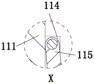
FIG. 5 is an enlarged view of the invention in section X of FIG. 2;
FIG. 6 is an enlarged view of the Y-direction portion of FIG. 3 of the present invention;
FIG. 7 is an enlarged view of the invention in the Z-direction of FIG. 3;
fig. 8 is an enlarged view of the invention in the direction of M of fig. 4.
Detailed Description
The embodiments of the invention will be described in detail below with reference to the drawings, but the invention can be implemented in many different ways, which are defined and covered by the claims.
As shown in fig. 1 to 8, the water and fertilizer integrated irrigation system for greenhouse planting comprises a frame 1, side watering mechanisms 2 and a top watering mechanism 3, wherein the side watering mechanisms 2 are symmetrically installed at the left lower end and the right lower end of the frame 1, and the top watering mechanism 3 is arranged in the middle of the upper end of the frame 1.
The frame 1 comprises a liquid storage box 10, a top plate 11, clamping pins 12, vertical plates 13, rotating shafts 14, rollers 16, tracks 17, a push handle 18 and a master controller 19, wherein the top plate 11 is installed on the upper end surface of the liquid storage box 10 in a sliding fit mode, the left and right ends of the top plate 11 are connected with the upper end of the liquid storage box 10 through the clamping pins 12, the vertical plates 13 are installed on the lower end surface of the liquid storage box 10 in a bilateral symmetry mode, the vertical plates 13 are in a front-back arrangement structure, the rotating shafts 14 are installed between the vertical plates 13 which are right opposite to each other in the left-right direction in a sliding fit mode, the rollers 16 are installed on the rotating shafts 14, the two rollers 16 are connected through the tracks 17, the push handle 18 is installed on the front end surface of the liquid storage box 10, the master controller 19 is installed on the front upper end surface of the push handle 18, a water-fertilizer mixed liquid is stored in the liquid storage box 10, the liquid storage box 10 is pushed by the tracks 18 in a manual mode, the liquid storage box 10 moves in ridges under the condition that the rollers 16 and the tracks 17, simultaneously, the side watering mechanism 2 is controlled by the master controller 19 to water the root and stem parts of crops, the top watering mechanism 3 conducts top-down sprinkling irrigation treatment on the tops of the crops, the crawler belt 17 is compared with the transmission of the independent roller 16, the contact area between the crawler belt and the ground is large, so that the whole equipment can adapt to the movement of uneven and soft ground, the integral relative stability degree of the equipment is further improved, after the equipment is used for one end time, the bayonet lock 12 can be pulled out in a manual mode, the top plate 11 can be taken down, then the liquid storage box 10 is cleaned, and the phenomenon that impurity scabs are formed in the liquid storage box 10 and the effect of the mixed liquid of water and fertilizer is influenced is avoided.
The fertilizer storage tank is characterized in that a first pipe hole is formed in the middle of the upper end of the front end face of the liquid storage tank 10, a water inlet pipe 101 is installed in the first pipe hole, the water inlet pipe 101 is of an L-shaped mechanism, the front upper end of the water inlet pipe 101 is connected with the lower end of a water storage barrel 102, a support plate 103 is installed at the middle lower end of the water storage barrel 102, the rear end of the support plate 103 is installed on the front end face of the liquid storage tank 10, a water plug 104 is installed in the middle of the upper end face of the water storage barrel 102 in a sliding fit mode, a second pipe hole is formed right behind the first pipe hole, the second pipe hole is formed in the rear end face of the liquid storage tank 10, an inclined pipe 105 is installed in the second pipe hole, the upper end of the inclined pipe 105 is connected with the lower end of a storage barrel 106, a connecting plate 107 is installed at the middle lower end of the storage barrel 106, the front end of the connecting plate 107 is installed on the rear end face of the liquid storage tank 10, clean water is poured into the liquid storage tank 10 through the water storage barrel 102, then the motor 112 drives the stirring blades 115 to rotate by means of the rotating shaft 111, and drives the stirring rod 11g to move through the electric slide block 11h, the stirring blades 115 and the stirring rod 11g are matched to fully and mechanically mix the clean water and the fertilizer, compared with the traditional manual stirring and mixing mode, the mechanical mixing mode can increase the mixing speed of the water and the fertilizer and reduce the labor intensity of workers, the workers can timely add the clean water and the fertilizer into the liquid storage tank 10 by means of the water storage barrel 102 and the material storage barrel 106 to ensure that the liquid storage tank 10 is always kept with the liquid fertilizer mixture before the crop irrigation is finished, and further the whole working time is shortened while the working efficiency is improved.
The water storage tank is characterized in that a hole groove is formed in the rear end of the left end face of the water inlet pipe 101, a control valve 10a is installed in the hole groove, the control valve 10a is located on the front side of the front end face of the water storage tank 10, a rotary column 10b is arranged right behind the water inlet pipe 101, the lower end of the rotary column 10b is installed on the inner bottom wall of the material storage tank 106 in a sliding fit mode, the rotary column 10b is located in the inner center of the material storage tank, the rotary column 10b is located right behind an inclined pipe 105, a partition plate 10c is installed on the rotary column 10b, the partition plates 10c are evenly distributed along the circumferential direction of the rotary column 10b, a sliding fit mode is formed between the outer side end of the partition plate 10c and the inner surface of the material storage tank 106, the inclined pipe 105 is located between adjacent partition plates 10c at the front end of the rotary column 10b, a water level line is arranged above the water inlet pipe 101 and is carved on the outer surface of the water storage tank 102, the water storage tank 102 is made of a transparent material, and the water storage tank 102 is filled with clear water manually, filling fertilizer between the partition boards 10c except the position of the inclined pipe 105, when fresh water and fertilizer are required to be added into the liquid storage tank 10, manually controlling the flow rate of the fresh water at the switching interval time of the control valve 10a, precisely controlling the flow rate of the fresh water according to the proportion ratio of the water-fertilizer mixed liquid under the condition of the scale mark on the water storage barrel 102, manually placing and rotating the partition boards 10c to enable the fertilizer between the partition boards 10c to be rotated to the position of the inclined pipe 105, sliding the fertilizer into the liquid storage tank 10 along the inclined pipe 105, placing the fertilizer storage amount between the adjacent partition boards 10c according to the proportion ratio of the water-fertilizer mixed liquid so that the fertilizer amount between the adjacent partition boards 10c is just the proportion amount of the primary water-fertilizer mixed liquid, and precisely controlling the arrangement of the control valve 10a, the rotary column 10b and the partition boards 10c to enable the use amount of the fresh water and the fertilizer to be controlled according to the proportion ratio of the single water-fertilizer mixed liquid, further ensuring the efficacy of the liquid fertilizer mixture to reach the best state, further shortening the working time of the whole work of crop irrigation on the basis of ensuring the irrigation quality.
The middle part of the upper end face of the top plate 11 is provided with a mounting through hole, a rotating shaft 111 is arranged in the mounting through hole through a bearing, the upper end of the rotating shaft 111 is connected with the output shaft end of the motor 112, the front and the back of the lower end face of the motor 112 are symmetrically provided with a bracket 113, the lower end of the bracket 113 is arranged on the upper end face of the top plate 11, the front and the back ends of the rotating shaft 111 are symmetrically provided with lug plate pairs 114, the lug plate pairs 114 are arranged at equal intervals from top to bottom, the lug plate pairs 114 are all positioned in the liquid storage tank 10, the outer side ends of the lug plate pairs 114 are provided with pin shafts, and stirring blades 115 are arranged on the pin shafts in a sliding fit manner, the rotating shaft 111 is driven to rotate by the motor 112, the stirring blades 115 are synchronously rotated along with the rotating shaft 111 and are simultaneously unfolded outwards, the stirring blades 115 can play a real-time stirring role on the liquid fertilizer mixed liquid in the liquid storage tank 10 so as to avoid the phenomenon that the liquid fertilizer mixed liquid is precipitated and layered to reduce the efficacy of the liquid fertilizer mixed liquid, and meanwhile, the stirring motion of the stirring blades 115 can also improve the mixing degree between water and fertilizer.
The utility model discloses a liquid storage tank, but U-shaped board 11 a's below longitudinal symmetry be provided with circular arc rail board 11f, circular arc rail board 11f is arranged about, circular arc rail board 11f installs at each four inside apex angles departments in liquid storage tank 10 upper end, electronic slider 11h is installed through sliding fit mode to the medial extremity of circular arc rail board 11f, the medial extremity of electronic slider 11h links to each other with the upper end of stirring rod 11g, stirring rod 11g is the lower extreme and leans out the structure, when stirring leaf 115 rotates along with axis of rotation 111, drive stirring rod 11g through electronic slider 11h and be reciprocating motion along circular arc rail board 11f, stirring rod 11g can stir near apex angle in the storage tank lower extreme in order to avoid liquid manure mixed liquid to form here and deposit, stirring rod 11g and stirring leaf 115's coordinated motion can make liquid manure mixed liquid everywhere in liquid storage tank 10 all be in the mobile state, and then improve the degree of mixing of liquid manure mixed liquid.
The lower part of the motor 112 is provided with a U-shaped plate 11a, the U-shaped plate 11a is positioned between the outer fixed hard tubes 31, the inner side end faces of the left and right ends of the U-shaped plate 11a are symmetrically provided with gear teeth 11b, the gear teeth 11b are equidistantly arranged from front to back, an incomplete gear 11c is arranged between the left and right ends of the U-shaped plate 11a, the incomplete gear 11c is arranged at the output shaft end of the motor 112, the incomplete gear 11c and the gear teeth 11b as well as the lower end face of the incomplete gear 11c and the upper end face of the top plate 11 are in a sliding fit mode, the left and right ends of the rear end of the U-shaped plate 11a are symmetrically provided with pull plates 11d, the pull plates 11d are in a structure with the front ends inclined upwards, the front ends of the pull plates 11d are connected with the rear end of a circular ring 11e, the circular ring 11e is provided with the left end of the outer fixed hard tubes 31, when the crop root and stem irrigation part is irrigated and irrigated from top to bottom, the motor 112 drives the rotating shaft 111 to rotate, incomplete gear 11c rotates along with it in step, incomplete gear 11c makes U template 11a drive arm-tie 11d to do reciprocating motion back and forth in step with the cooperation between the teeth of a cogwheel 11b, arm-tie 11d stimulates outer solid hard tube 31 and carries out reciprocating motion back and forth in step, outer solid hard tube 31 drives a watering pipe 32 and hollow extension board 33 synchronous rotation, stretch board 33 from the hollow and carry liquid manure and be convex sprinkling irrigation in order to improve the sprinkling irrigation scope, and then improve the efficiency of crop sprinkling irrigation, also avoid appearing the local too much phenomenon of sprinkling irrigation of liquid manure mixture simultaneously.
The side pouring mechanism 2 comprises a base 20, vertical blocks 21, a shaft rod 22, a hollow rotating plate 23, adjusting nuts 24, spray heads 25 and side pouring water pipes 26, wherein the inner side end of the base 20 is installed at the lower end of the outer side end face in the left-right direction of the liquid storage tank 10, the vertical blocks 21 are symmetrically installed at the front and back of the upper end of the base 20, the shaft rod 22 is installed between the vertical blocks 21 in a sliding fit mode, the hollow rotating plate 23 is installed on the shaft rod 22, the adjusting nuts 24 are installed at the rear end of the shaft rod 22 in a thread fit mode, the front ends of the adjusting nuts 24 and the rear ends of the vertical blocks 21 at the rear end of the shaft rod 22 are in a thread fit mode, the spray heads 25 are symmetrically installed at the front and back of the outer side end face of the hollow rotating plate 23 in a thread fit mode, the spray heads 25 are vertically arranged, the side pouring water pipes 26 are installed at the front and back of the inner side ends of the hollow rotating plate 23 in a thread fit mode, the inner side pouring water pipes 26 are connected with pipe holes in a sliding fit mode, the pipe hole is arranged at the lower end of the left end face of the liquid storage box 10, the right lower end face of the side watering pipe 26 is positioned above the left side of the inner bottom wall of the liquid storage box 10, the left end of the side watering pipe 26 is of a telescopic structure, the adjusting nut 24 is loosened and the rotating plate is rotated to be adjusted by a certain angle in a manual mode, then the adjusting nut 24 is screwed again to fix the rotating plate, the rotating plate drives the telescopic section of the side watering pipe 26 to synchronously extend or contract in the rotating process, then the water-fertilizer mixed liquid in the side watering pipe 26 is controlled to be injected through the controller 19, the water-fertilizer mixed liquid is injected through the spray head 25 to irrigate the roots of crops, the irrigation mode of the roots of the crops formed by matching among the hollow rotating plate 23, the adjusting nut 24, the spray head 25 and the side watering pipe 26 is compared with the traditional simple sprinkling irrigation mode of top-down irrigation of the crops, the former can improve the homogenization degree of irrigation of the crops so as to avoid the phenomenon of missing irrigation of crops, meanwhile, the absorption rate of crops and soil to the water and fertilizer mixed solution can be improved.
The front end of the vertical block 21 at the rear end of the shaft lever 22 is provided with an angle scale 221, the lower end of the angle scale 221 is installed on the upper end face of the base 20, the angle scale 221, the shaft lever 22 and the rear end face of the hollow rotating plate 23 are in sliding fit, and workers can perform adaptive adjustment on the rotating angle of the rotating plate by means of the angle scale 221 so that the rotating plate carrying spray heads 25 are suitable for irrigation treatment of roots of crops of different height dimension types.
The top pouring mechanism 3 comprises an outer fixed hard pipe 31, a top pouring water pipe 32 and a hollow extension plate 33, the lower end of the outer fixed hard pipe 31 is arranged on the upper end surface of the top plate 11 in a bilateral symmetry mode in a sliding fit mode, the outer fixed hard pipe 31 is of an inverted L-shaped structure, the top pouring water pipe 32 is arranged in the outer fixed hard pipe 31, the top pouring water pipe 32 is of an inverted L-shaped structure, the lower end surface of the top pouring water pipe 32 is positioned above the inner bottom wall of the liquid storage box 10, the top pouring water pipe 32 is positioned between the inner side ends of the side pouring water pipes 26, the hollow extension plate 33 is arranged on the outer end surface of the outer fixed hard pipe 31, the outer end surface of the top pouring water pipe 32 is positioned in the hollow extension plate 33, the lower end surface of the hollow extension plate 33 is provided with water outlets at equal intervals from left to right, the water outlets are arranged at equal intervals from front to back, the controller 19 is used for controlling the injection of water-fertilizer mixed liquid in the top pouring water pipe 32, the water-fertilizer mixed liquid flows into the hollow extension plate 33 from the top pouring water pipe 32, and the water is sprayed out from a water outlet hole at the lower end of the hollow extension plate 33 to spray crops from top to bottom, the top watering mechanism 3 and the side watering mechanism 2 are matched to improve the crop spraying efficiency, and meanwhile, the watering area of crops is also increased.
When the device works, clear water is filled in the water storage barrel 102 in a manual mode, fertilizers are filled between the partition plates 10c except the position of the inclined pipe 105, then when the clear water and the fertilizers are required to be added into the liquid storage box 10, the flow of the clear water is controlled at the switching interval time of the control valve 10a in a manual mode, under the condition of the help of the scale marks on the water storage barrel 102, the flow of the clear water is controlled accurately according to the proportion ratio of the liquid fertilizer mixture, the fertilizers between the partition plates 10c are rotated to the position of the inclined pipe 105 through manually placing and rotating the partition plates 10c, the fertilizers slide into the liquid storage box 10 along the inclined pipes 105, the fertilizer storage amount between the adjacent partition plates 10c can be placed according to the proportion ratio of the liquid fertilizer mixture so that the fertilizer amount between the adjacent partition plates 10c is just equal to the proportion of the liquid fertilizer mixture at one time, and the corresponding amount of the clear water and the fertilizers are added into the liquid storage box 10, the motor 112 drives the rotating shaft 111 to rotate, the stirring blades 115 synchronously rotate along with the rotating shaft 111 and simultaneously expand outwards, the stirring blades 115 can stir the liquid manure mixed liquid in the liquid storage box 10 in real time, meanwhile, the electric slide block 11h drives the stirring rod 11g to reciprocate along the arc rail plate 11f, the stirring rod 11g can stir the vicinity of the inner vertex angle of the lower end of the liquid storage box so as to prevent the liquid manure mixed liquid from forming sediment at the position, then the adjusting nut 24 is loosened manually and the rotating plate is rotated to be adjusted to a corresponding angle according to the size of the root and stem of crops, then the adjusting nut 24 is screwed again to fix the rotating plate, the rotating plate drives the telescopic section of the side watering pipe 26 to synchronously extend or contract in the rotating process, then the liquid storage box 10 is manually pushed by the aid of the hand push handle 18, and the liquid storage box 10 moves among ridges under the condition of the aid of the rollers 16 and the tracks 17, meanwhile, after the master controller 19 is communicated, the master controller 19 controls the injection of the water-fertilizer mixed liquid in the side watering pipe 26, the water-fertilizer mixed liquid is sprayed out through the spray head 25 to irrigate the roots of crops, and controls the injection of the water-fertilizer mixed liquid in the top watering pipe 32, the water-fertilizer mixed liquid flows from the top watering pipe 32 into the hollow extension plate 33 and is sprayed out through a water outlet at the lower end of the hollow extension plate 33 to spray the crops from top to bottom, when the crops are irrigated at the roots and sprayed from top to bottom, the motor 112 drives the rotating shaft 111 to rotate, the incomplete gear 11c synchronously rotates along with the rotating shaft, the incomplete gear 11c is matched with the gear teeth 11b, so that the U-shaped plate 11a drives the pull plate 11d to synchronously reciprocate back and forth, the pull plate 11d drives the outer fixing hard pipe 31 to synchronously reciprocate back and forth, the outer fixing hard pipe 31 drives the top watering pipe 32 and the hollow extension plate 33 to synchronously rotate, the water and fertilizer mixed liquid carried by the hollow extension plate 33 is sprayed in a circular arc shape to improve the spraying range, so that the efficiency of crop spraying is improved.
Furthermore, it should be understood that although the present description refers to embodiments, not every embodiment may contain only a single embodiment, and such description is for clarity only, and those skilled in the art should integrate the description, and the embodiments may be combined as appropriate to form other embodiments understood by those skilled in the art.
Claims (7)
1. The utility model provides a water and fertilizer integration irrigation system is planted to big-arch shelter, includes that frame (1), side water mechanism (2) and top water mechanism (3), its characterized in that: the left lower end and the right lower end of the frame (1) are symmetrically provided with side pouring mechanisms (2), and the middle part of the upper end of the frame (1) is provided with a top pouring mechanism (3);
the frame (1) comprises a liquid storage box (10), a top plate (11), a bayonet (12), a vertical plate (13), a rotating shaft (14), a roller (16), a crawler belt (17), a push handle (18) and a master controller (19), the upper end face of the liquid storage box (10) is provided with a top plate (11) in a sliding fit mode, the left end and the right end of the top plate (11) are connected with the upper end of the liquid storage box (10) through clamping pins (12), vertical plates (13) are symmetrically arranged on the left side and the right side of the lower end face of the liquid storage box (10), the vertical plates (13) are in a front-back arrangement structure, a rotating shaft (14) is arranged between the vertical plates (13) which are right opposite to the left side and the right side in a sliding fit mode, rollers (16) are arranged on the rotating shaft (14), the two rollers (16) are connected through a crawler belt (17), the front end face of the liquid storage box (10) is provided with a push handle (18), and the front upper end face of the push handle (18) is provided with a master controller (19);
the side pouring mechanism (2) comprises a base (20), vertical blocks (21), a shaft rod (22), a hollow rotating plate (23), adjusting nuts (24), spray heads (25) and side pouring water pipes (26), wherein the inner side end of the base (20) is installed at the lower end of the outer side end face in the left-right direction of the liquid storage tank (10), the vertical blocks (21) are symmetrically installed at the front and back of the upper end of the base (20), the shaft rod (22) is installed between the vertical blocks (21) in a sliding fit mode, the hollow rotating plate (23) is installed on the shaft rod (22), the adjusting nuts (24) are installed at the rear end of the shaft rod (22) in a thread fit mode, the screw threads are matched between the front end of each adjusting nut (24) and the rear end of the vertical block (21) at the rear end of the shaft rod (22), the spray heads (25) are symmetrically installed at the front and back of the outer side end face of the hollow rotating plate (23) in a thread fit mode, and the spray heads (25) are arranged up and down, a side watering pipe (26) is arranged in a threaded fit manner in front and at back of the inner side end of the hollow rotating plate (23), the inner side end of the side watering pipe (26) is connected with a pipe hole in a sliding fit manner, the pipe hole is formed in the lower end of the left end face of the liquid storage tank (10), the right lower end face of the side watering pipe (26) is positioned above the left side of the inner bottom wall of the liquid storage tank (10), and the left end of the side watering pipe (26) is of a telescopic structure;
the top pouring mechanism (3) comprises an outer fixed hard pipe (31), a top pouring water pipe (32) and a hollow extending plate (33), the lower end of the outer fixed hard pipe (31) is installed on the upper end face of the top plate (11) in a sliding fit mode in a bilateral symmetry mode, the outer fixed hard pipe (31) is of an inverted L-shaped structure, the top pouring water pipe (32) is installed in the outer fixed hard pipe (31), the top pouring water pipe (32) is of an inverted L-shaped structure, the lower end face of the top pouring water pipe (32) is located above the inner bottom wall of the liquid storage tank (10), the top pouring water pipe (32) is located between the inner side ends of the side pouring water pipes (26), the hollow extending plate (33) is installed on the outer end face of the outer fixed hard pipe (31), the outer end of the top pouring water pipe (32) is located inside the hollow extending plate (33), water outlets are formed in the mode that the lower end face of the hollow extending plate (33) is arranged from left to right at equal intervals, and are arranged from front to back at equal intervals;
compression springs (231) are symmetrically installed at the left lower end and the right lower end of the hollow rotating plate (23), the compression springs (231) are arranged in a front-back mode, the outer side ends of the compression springs (231) are installed on the upper end face of the base (20), and the compression springs (231) are of an upward inclined structure.
2. The greenhouse planting water and fertilizer integrated irrigation system as claimed in claim 1, wherein: the up end middle part of roof (11) seted up the installation through-hole, axis of rotation (111) are installed to the installation through-hole inner bearing, the upper end of axis of rotation (111) links to each other with the output axle head of motor (112), support (113) are installed to the front and back symmetry of the lower terminal surface of motor (112), the up end at roof (11) is installed to the lower extreme of support (113), the otic placode is installed to the front and back both ends symmetry of axis of rotation (111) to (114), the otic placode is arranged from last down equidistance to (114), the otic placode all is located liquid reserve tank (10) to (114), the round pin axle is installed to the outside end of (114) to the otic placode, it stirs leaf (115) to install through sliding fit mode on the round pin axle.
3. The greenhouse planting water and fertilizer integrated irrigation system as claimed in claim 2, wherein: the motor (112) is provided with a U-shaped plate (11a) below, the U-shaped plate (11a) is located between the outer fixed hard tubes (31), gear teeth (11b) are symmetrically installed on the end faces of the inner sides of the left end and the right end of the U-shaped plate (11a), the gear teeth (11b) are arranged equidistantly from front to back, an incomplete gear (11c) is arranged between the left end and the right end of the U-shaped plate (11a), the incomplete gear (11c) is installed at the output shaft end of the motor (112), the incomplete gear (11c), the gear teeth (11b), the lower end face of the incomplete gear (11c) and the upper end face of the top plate (11) are in sliding fit, pull plates (11d) are symmetrically installed on the left end and the right end of the rear end of the U-shaped plate (11a), the pull plates (11d) are of a structure with the front ends inclined upwards, the front ends of the pull plates (11d) are connected with the rear ends of rings (11e), and the rings (11e) are provided with the left ends of the outer fixed hard tubes (31).
4. The greenhouse planting water and fertilizer integrated irrigation system as claimed in claim 3, wherein: the utility model discloses a motor vehicle stirring device, including U template (11a), circular arc rail board (11f) are provided with to the below longitudinal symmetry of U template (11a), arrange about circular arc rail board (11f), four inside apex angles departments in liquid reserve tank (10) upper end are installed in circular arc rail board (11f), electronic slider (11h) are installed through sliding fit mode to the medial extremity of circular arc rail board (11f), the medial extremity of electronic slider (11h) links to each other with the upper end of stirring rod (11g), stirring rod (11g) are the lower extreme and lean out the structure.
5. The greenhouse planting water and fertilizer integrated irrigation system as claimed in claim 1, wherein: the upper end middle part of the preceding terminal surface of liquid reserve tank (10) seted up the tube hole No. one, install inlet tube (101) in the tube hole No. one, inlet tube (101) are L type mechanism, the preceding upper end of inlet tube (101) links to each other with the lower extreme of water storage bucket (102), extension board (103) are installed to well lower extreme of water storage bucket (102), the preceding terminal surface at liquid reserve tank (10) is installed to the rear end of extension board (103), water plug (104) are installed through sliding fit mode in the up end middle part of water storage bucket (102), be provided with No. two tube holes directly behind the tube hole, No. two tube holes are seted up at the rear end of liquid reserve tank (10), install slope pipe (105) in No. two tube holes, the upper end of slope pipe (105) links to each other with the lower extreme of storage vat (106), connecting plate (107) are installed to well lower extreme of storage vat (106), the rear end at liquid reserve tank (10) is installed to the front end of connecting plate (107).
6. The greenhouse planting water and fertilizer integrated irrigation system as claimed in claim 5, wherein: the water storage tank is characterized in that a hole groove is formed in the rear end of the left end face of the water inlet pipe (101), a control valve (10a) is installed in the hole groove, the control valve (10a) is located on the front side of the front end face of the water storage tank (10), a rotary column (10b) is arranged right behind the water inlet pipe (101), the lower end of the rotary column (10b) is installed on the inner bottom wall of the material storage barrel (106) in a sliding fit mode, the rotary column (10b) is located in the inner center of the material storage tank, the rotary column (10b) is located right behind the inclined pipe (105), a partition plate (10c) is installed on the rotary column (10b), the partition plates (10c) are evenly distributed along the circumferential direction of the rotary column (10b), a sliding fit mode is formed between the outer side end of the partition plate (10c) and the inner surface of the material storage barrel (106), the inclined pipe (105) is located between adjacent partition plates (10c) at the front end of the rotary column (10b), a water level line is arranged above the water inlet pipe (101), the water level line is carved on the outer surface of the water storage barrel (102), and the water storage barrel (102) is made of transparent material.
7. The greenhouse planting water and fertilizer integrated irrigation system as claimed in claim 1, wherein: the front end of the rear end vertical block (21) of the shaft lever (22) is provided with an angle scale (221), the lower end of the angle scale (221) is installed on the upper end face of the base (20), and the angle scale (221) is in sliding fit with the rear end faces of the shaft lever (22) and the hollow rotating plate (23).
Priority Applications (1)
| Application Number | Priority Date | Filing Date | Title |
|---|---|---|---|
| CN202010468906.1A CN111527947B (en) | 2020-05-28 | 2020-05-28 | Water and fertilizer integrated irrigation system for greenhouse planting |
Applications Claiming Priority (1)
| Application Number | Priority Date | Filing Date | Title |
|---|---|---|---|
| CN202010468906.1A CN111527947B (en) | 2020-05-28 | 2020-05-28 | Water and fertilizer integrated irrigation system for greenhouse planting |
Publications (2)
| Publication Number | Publication Date |
|---|---|
| CN111527947A CN111527947A (en) | 2020-08-14 |
| CN111527947B true CN111527947B (en) | 2021-10-26 |
Family
ID=71968250
Family Applications (1)
| Application Number | Title | Priority Date | Filing Date |
|---|---|---|---|
| CN202010468906.1A Active CN111527947B (en) | 2020-05-28 | 2020-05-28 | Water and fertilizer integrated irrigation system for greenhouse planting |
Country Status (1)
| Country | Link |
|---|---|
| CN (1) | CN111527947B (en) |
Families Citing this family (2)
| Publication number | Priority date | Publication date | Assignee | Title |
|---|---|---|---|---|
| CN112889446A (en) * | 2021-02-01 | 2021-06-04 | 王瑾 | Farming liquid manure integrated device |
| CN116076214A (en) * | 2022-12-28 | 2023-05-09 | 吉林省林业科学研究院 | A water-fertilizer coupling device and method for regulating hazelnut yield and quality |
Citations (9)
| Publication number | Priority date | Publication date | Assignee | Title |
|---|---|---|---|---|
| WO2002006713A2 (en) * | 2000-07-13 | 2002-01-24 | Dieter Garner | Coupling system and automatic coupling method |
| DE202012011208U1 (en) * | 2012-11-16 | 2012-12-19 | Yuan Pin Industrial Co., Ltd. | Swiveling water sprinkler |
| CN104386636A (en) * | 2014-10-20 | 2015-03-04 | 中山弘博企业管理咨询有限公司 | A weighing type quantitative filling machine |
| CN204193834U (en) * | 2014-11-04 | 2015-03-11 | 贵州欧瑞信环保科技有限责任公司 | A kind of automatic tightening formula agitating device |
| CN108271492A (en) * | 2018-02-01 | 2018-07-13 | 浦江县宏创科技开发有限公司 | A kind of water conservancy irrigation torch-type nutrient solution flusher |
| CN209057516U (en) * | 2018-09-19 | 2019-07-05 | 张雷贤 | A kind of afforestation fertilising irrigation device |
| CN210042876U (en) * | 2019-06-12 | 2020-02-11 | 海南大学 | Energy-saving agricultural watering device |
| CN210247810U (en) * | 2019-05-14 | 2020-04-07 | 奉节县衍禹农业开发有限公司 | Rhubarb is planted and is used watering device |
| CN210537948U (en) * | 2019-08-02 | 2020-05-19 | 漳州新镇宇生物科技有限公司 | Butterfly orchid cultivation irrigation equipment |
-
2020
- 2020-05-28 CN CN202010468906.1A patent/CN111527947B/en active Active
Patent Citations (9)
| Publication number | Priority date | Publication date | Assignee | Title |
|---|---|---|---|---|
| WO2002006713A2 (en) * | 2000-07-13 | 2002-01-24 | Dieter Garner | Coupling system and automatic coupling method |
| DE202012011208U1 (en) * | 2012-11-16 | 2012-12-19 | Yuan Pin Industrial Co., Ltd. | Swiveling water sprinkler |
| CN104386636A (en) * | 2014-10-20 | 2015-03-04 | 中山弘博企业管理咨询有限公司 | A weighing type quantitative filling machine |
| CN204193834U (en) * | 2014-11-04 | 2015-03-11 | 贵州欧瑞信环保科技有限责任公司 | A kind of automatic tightening formula agitating device |
| CN108271492A (en) * | 2018-02-01 | 2018-07-13 | 浦江县宏创科技开发有限公司 | A kind of water conservancy irrigation torch-type nutrient solution flusher |
| CN209057516U (en) * | 2018-09-19 | 2019-07-05 | 张雷贤 | A kind of afforestation fertilising irrigation device |
| CN210247810U (en) * | 2019-05-14 | 2020-04-07 | 奉节县衍禹农业开发有限公司 | Rhubarb is planted and is used watering device |
| CN210042876U (en) * | 2019-06-12 | 2020-02-11 | 海南大学 | Energy-saving agricultural watering device |
| CN210537948U (en) * | 2019-08-02 | 2020-05-19 | 漳州新镇宇生物科技有限公司 | Butterfly orchid cultivation irrigation equipment |
Also Published As
| Publication number | Publication date |
|---|---|
| CN111527947A (en) | 2020-08-14 |
Similar Documents
| Publication | Publication Date | Title |
|---|---|---|
| CN108739291A (en) | A kind of adjustable hand propelled water injector of spray radius | |
| CN108684499A (en) | A kind of adjustable agricultural irrigation device of nozzle | |
| CN211793934U (en) | Novel fruit tree is planted with irrigating spraying device | |
| CN112741072A (en) | Orchard planting-based pesticide spraying and fertilizing integrated device and use method | |
| CN111527947A (en) | Water and fertilizer integrated irrigation system for greenhouse planting | |
| CN218184245U (en) | Crop seedling raising device | |
| CN215683760U (en) | Automatic tea sapling breeding device that sprays and irrigate | |
| CN213784587U (en) | A special water-saving irrigation device for horticultural flowers | |
| CN210900613U (en) | Flowers artificial containers is used in gardens | |
| CN208370544U (en) | A kind of irrigation system in forest growing and cultivation | |
| CN214482246U (en) | Landscape architecture construction is with curing means who is convenient for fertilize | |
| CN207733242U (en) | Water integrated device is applied in a kind of orchard | |
| CN211353258U (en) | Farming is with device of growing seedlings | |
| CN211558307U (en) | Farmland irrigation equipment | |
| CN220476437U (en) | Breeding case is used in crops breeding | |
| CN102845292A (en) | Rotary aeroponic cultivation device | |
| CN223829925U (en) | Accurate drip irrigation and fertilization integrated device for rose planting | |
| CN215530239U (en) | Gardens potted plant curing means | |
| CN208113626U (en) | A kind of gardens combined type flower sprinkling control fertilizer integrated apparatus | |
| CN210298551U (en) | A liquid manure irrigation equipment for gardens | |
| CN221409771U (en) | Efficient water-saving irrigation device for planting butterfly orchid in greenhouse | |
| CN223639809U (en) | A greenhouse sprinkler irrigation device | |
| CN221011112U (en) | Plant planting cuttage seedbed | |
| CN222685574U (en) | Slope trimming device for civil engineering | |
| CN218977818U (en) | Seedling deinsectization device |
Legal Events
| Date | Code | Title | Description |
|---|---|---|---|
| PB01 | Publication | ||
| PB01 | Publication | ||
| SE01 | Entry into force of request for substantive examination | ||
| SE01 | Entry into force of request for substantive examination | ||
| GR01 | Patent grant | ||
| GR01 | Patent grant |