CN111517246A - Portable hand electric fork-lift - Google Patents
Portable hand electric fork-lift Download PDFInfo
- Publication number
- CN111517246A CN111517246A CN202010297914.4A CN202010297914A CN111517246A CN 111517246 A CN111517246 A CN 111517246A CN 202010297914 A CN202010297914 A CN 202010297914A CN 111517246 A CN111517246 A CN 111517246A
- Authority
- CN
- China
- Prior art keywords
- frame
- front fork
- connecting rod
- boom
- rod
- Prior art date
- Legal status (The legal status is an assumption and is not a legal conclusion. Google has not performed a legal analysis and makes no representation as to the accuracy of the status listed.)
- Granted
Links
Images


Classifications
-
- B—PERFORMING OPERATIONS; TRANSPORTING
- B66—HOISTING; LIFTING; HAULING
- B66F—HOISTING, LIFTING, HAULING OR PUSHING, NOT OTHERWISE PROVIDED FOR, e.g. DEVICES WHICH APPLY A LIFTING OR PUSHING FORCE DIRECTLY TO THE SURFACE OF A LOAD
- B66F9/00—Devices for lifting or lowering bulky or heavy goods for loading or unloading purposes
- B66F9/06—Devices for lifting or lowering bulky or heavy goods for loading or unloading purposes movable, with their loads, on wheels or the like, e.g. fork-lift trucks
- B66F9/075—Constructional features or details
- B66F9/07504—Accessories, e.g. for towing, charging, locking
-
- B—PERFORMING OPERATIONS; TRANSPORTING
- B66—HOISTING; LIFTING; HAULING
- B66F—HOISTING, LIFTING, HAULING OR PUSHING, NOT OTHERWISE PROVIDED FOR, e.g. DEVICES WHICH APPLY A LIFTING OR PUSHING FORCE DIRECTLY TO THE SURFACE OF A LOAD
- B66F9/00—Devices for lifting or lowering bulky or heavy goods for loading or unloading purposes
- B66F9/06—Devices for lifting or lowering bulky or heavy goods for loading or unloading purposes movable, with their loads, on wheels or the like, e.g. fork-lift trucks
- B66F9/075—Constructional features or details
- B66F9/07513—Details concerning the chassis
-
- B—PERFORMING OPERATIONS; TRANSPORTING
- B66—HOISTING; LIFTING; HAULING
- B66F—HOISTING, LIFTING, HAULING OR PUSHING, NOT OTHERWISE PROVIDED FOR, e.g. DEVICES WHICH APPLY A LIFTING OR PUSHING FORCE DIRECTLY TO THE SURFACE OF A LOAD
- B66F9/00—Devices for lifting or lowering bulky or heavy goods for loading or unloading purposes
- B66F9/06—Devices for lifting or lowering bulky or heavy goods for loading or unloading purposes movable, with their loads, on wheels or the like, e.g. fork-lift trucks
- B66F9/075—Constructional features or details
- B66F9/07554—Counterweights
-
- B—PERFORMING OPERATIONS; TRANSPORTING
- B66—HOISTING; LIFTING; HAULING
- B66F—HOISTING, LIFTING, HAULING OR PUSHING, NOT OTHERWISE PROVIDED FOR, e.g. DEVICES WHICH APPLY A LIFTING OR PUSHING FORCE DIRECTLY TO THE SURFACE OF A LOAD
- B66F9/00—Devices for lifting or lowering bulky or heavy goods for loading or unloading purposes
- B66F9/06—Devices for lifting or lowering bulky or heavy goods for loading or unloading purposes movable, with their loads, on wheels or the like, e.g. fork-lift trucks
- B66F9/075—Constructional features or details
- B66F9/07586—Suspension or mounting of wheels on chassis
-
- B—PERFORMING OPERATIONS; TRANSPORTING
- B66—HOISTING; LIFTING; HAULING
- B66F—HOISTING, LIFTING, HAULING OR PUSHING, NOT OTHERWISE PROVIDED FOR, e.g. DEVICES WHICH APPLY A LIFTING OR PUSHING FORCE DIRECTLY TO THE SURFACE OF A LOAD
- B66F9/00—Devices for lifting or lowering bulky or heavy goods for loading or unloading purposes
- B66F9/06—Devices for lifting or lowering bulky or heavy goods for loading or unloading purposes movable, with their loads, on wheels or the like, e.g. fork-lift trucks
- B66F9/075—Constructional features or details
- B66F9/0759—Details of operating station, e.g. seats, levers, operator platforms, cabin suspension
-
- B—PERFORMING OPERATIONS; TRANSPORTING
- B66—HOISTING; LIFTING; HAULING
- B66F—HOISTING, LIFTING, HAULING OR PUSHING, NOT OTHERWISE PROVIDED FOR, e.g. DEVICES WHICH APPLY A LIFTING OR PUSHING FORCE DIRECTLY TO THE SURFACE OF A LOAD
- B66F9/00—Devices for lifting or lowering bulky or heavy goods for loading or unloading purposes
- B66F9/06—Devices for lifting or lowering bulky or heavy goods for loading or unloading purposes movable, with their loads, on wheels or the like, e.g. fork-lift trucks
- B66F9/075—Constructional features or details
- B66F9/12—Platforms; Forks; Other load supporting or gripping members
- B66F9/122—Platforms; Forks; Other load supporting or gripping members longitudinally movable
-
- B—PERFORMING OPERATIONS; TRANSPORTING
- B66—HOISTING; LIFTING; HAULING
- B66F—HOISTING, LIFTING, HAULING OR PUSHING, NOT OTHERWISE PROVIDED FOR, e.g. DEVICES WHICH APPLY A LIFTING OR PUSHING FORCE DIRECTLY TO THE SURFACE OF A LOAD
- B66F9/00—Devices for lifting or lowering bulky or heavy goods for loading or unloading purposes
- B66F9/06—Devices for lifting or lowering bulky or heavy goods for loading or unloading purposes movable, with their loads, on wheels or the like, e.g. fork-lift trucks
- B66F9/075—Constructional features or details
- B66F9/20—Means for actuating or controlling masts, platforms, or forks
- B66F9/22—Hydraulic devices or systems
Landscapes
- Engineering & Computer Science (AREA)
- Transportation (AREA)
- Structural Engineering (AREA)
- Civil Engineering (AREA)
- Life Sciences & Earth Sciences (AREA)
- Geology (AREA)
- Mechanical Engineering (AREA)
- Chemical & Material Sciences (AREA)
- Combustion & Propulsion (AREA)
- Forklifts And Lifting Vehicles (AREA)
Abstract
Description
技术领域technical field
本公开一般涉及叉车设备技术领域,具体涉及一种便携式的手扶电动叉车。The present disclosure generally relates to the technical field of forklift equipment, and in particular relates to a portable hand-held electric forklift.
背景技术Background technique
叉车是工业搬运车辆,是指对成件托盘货物进行装卸、堆垛和短距离运输作业的各种轮式搬运车辆;工业搬运车辆广泛应用于港口、车站、机场、货场、工厂车间、仓库、流通中心和配送中心等,在船舱、车厢和集装箱内进行托盘货物的装卸、搬运作业,是托盘运输、集装箱运输中必不可少的设备;Forklifts are industrial handling vehicles, which refer to various wheeled handling vehicles for loading, unloading, stacking and short-distance transportation of palletized goods; industrial handling vehicles are widely used in ports, stations, airports, freight yards, factory workshops, warehouses, Circulation centers and distribution centers, etc., carry out loading, unloading, and handling operations of palletized goods in cabins, carriages and containers, and are essential equipment in pallet transportation and container transportation;
目前,对于起重量较大的货物而言,以及较大的港口、机场和工厂车间而言,多数情况下,需要车载型叉车以及小型推动叉车进行配合使用,车载型叉车在使用过程中多数是通过人为驾驶车辆进行搬运以及升降货物,其效率较高,但是车载型叉车的成本较高,以及其适用于长距离搬运,并且车载型叉车适用于较大面积的场地;对于小型工厂搬运货物而言,使用车载型叉车的成本较高,并且场地较小的情况下,不便于移动,甚至还有可能造成一定的安全事故,此时,小型推动叉车更加能够贴合实际的搬运需求;At present, for goods with large lifting weight, as well as large ports, airports and factory workshops, in most cases, truck-mounted forklifts and small push forklifts are required to be used together. It is more efficient to carry and lift goods by human-driven vehicles, but the cost of truck-mounted forklifts is high, and it is suitable for long-distance transportation, and truck-mounted forklifts are suitable for larger areas; In other words, the cost of using a truck-mounted forklift is high, and when the site is small, it is inconvenient to move, and it may even cause certain safety accidents. At this time, a small push forklift can better meet the actual handling needs;
目前市场上存在的小型推动叉车多数为手动液压型叉车,其多数起到转运货物的作用,手动液压型叉车的缺陷在于针对需要装卸的货物而言,其上升的高度有限,多数仍需要人力进行装货和卸货过程,并且对于手动液压叉车而言,其自身重量较重,无法做到随车携带,因此,我们提出一种便携式的手扶电动叉车,用来解决现有叉车存在的搬运难,效率低以及人力成本高的问题。At present, most of the small push forklifts on the market are manual hydraulic forklifts, and most of them play the role of transferring goods. The disadvantage of manual hydraulic forklifts is that for the goods that need to be loaded and unloaded, their lifting height is limited, and most still require manpower. The loading and unloading process, and for the manual hydraulic forklift, its own weight is heavy and cannot be carried with the vehicle. Therefore, we propose a portable hand-held electric forklift to solve the handling difficulties of the existing forklift. , low efficiency and high labor costs.
发明内容SUMMARY OF THE INVENTION
鉴于现有技术中的上述缺陷或不足,期望提供一种能够随车携带,方便、快捷地装卸货物,节省人力,结构简单且易于实现的便携式的手扶电动叉车。In view of the above-mentioned defects or deficiencies in the prior art, it is desirable to provide a portable hand-held electric forklift that can be carried with the vehicle, conveniently and quickly loads and unloads goods, saves manpower, and has a simple and easy-to-implement structure.
第一方面,本申请提供一种便携式的手扶电动叉车,包括:第一车架和设置在所述第一车架上的第二车架;In a first aspect, the present application provides a portable walk-behind electric forklift, comprising: a first frame and a second frame disposed on the first frame;
所述第一车架包括:车架和两个平行设置的斜梁;所述车架呈U型结构,所述车架设置有两个平行设置的前叉腿;每个所述前叉腿的端部设置有第一脚轮;所述车架远离所述前叉腿的一侧设置有两个平行设置的横梁;所述横梁的端部设置有第二脚轮;两个所述斜梁之间设置有平行设置的第一连接杆与第二连接杆,且所述第二连接杆位于两个所述斜梁的端部;The first frame includes: a frame and two inclined beams arranged in parallel; the frame is in a U-shaped structure, and the frame is provided with two front fork legs arranged in parallel; each of the front fork legs The end of the frame is provided with a first caster; the side of the frame away from the front fork leg is provided with two parallel beams; the end of the beam is provided with a second caster; A first connecting rod and a second connecting rod arranged in parallel are arranged between them, and the second connecting rod is located at the ends of the two inclined beams;
所述第二车架包括:起重臂和前叉立梁;所述起重臂设置在所述第一连接杆上,且所述起重臂连接有驱动组件;所述前叉立梁固接在所述起重臂的端部;所述前叉立梁上设置有前叉;所述前叉立梁与所述第二连接杆之间设有平衡拉杆;所述平衡拉杆分别与所述前叉立梁、所述第二连接杆可旋转连接;;所述起重臂上还开设有长条孔;所述长条孔的边沿设置有两个对称设置的拉称;两个所述拉称之间设置有连接轴。The second frame includes: a boom and a front fork vertical beam; the boom is arranged on the first connecting rod, and a drive assembly is connected to the boom; the front fork vertical beam is fixed connected to the end of the boom; the front fork vertical beam is provided with a front fork; a balance pull rod is arranged between the front fork vertical beam and the second connecting rod; the balance pull rod is respectively connected to the The front fork vertical beam and the second connecting rod are rotatably connected; the boom is also provided with a long hole; the edge of the long hole is provided with two symmetrically arranged tension scales; A connecting shaft is arranged between the said pull scales.
根据本申请实施例提供的技术方案,所述驱动组件包括:油缸和蓄电池;所述油缸设置在所述车架上,且所述油缸位于两个所述第二支撑杆之间;所述油缸的活塞杆固接有伸缩杆,且所述伸缩杆的端部贯穿所述长条孔固接在所述连接轴上;所述蓄电池能够设置在任一所述斜梁的侧壁上、所述车架的表面或者所述车架靠近所述横梁的侧壁上;每个所述斜梁的外壁上设置有扶手,所述扶手靠近所述斜梁的端部,且两个所述扶手对称设置;任一所述斜梁的端部还设置有控制开关,且所述控制开关与所述扶手相邻设置;所述蓄电池通过导线分别与所述油缸、所述控制开关连接。According to the technical solutions provided by the embodiments of the present application, the drive assembly includes: an oil cylinder and a battery; the oil cylinder is arranged on the frame, and the oil cylinder is located between the two second support rods; the oil cylinder The piston rod is fixed with a telescopic rod, and the end of the telescopic rod is fixed on the connecting shaft through the long hole; the battery can be arranged on the side wall of any of the inclined beams, the The surface of the frame or the side wall of the frame close to the beam; the outer wall of each inclined beam is provided with a handrail, the handrail is close to the end of the inclined beam, and the two handrails are symmetrical The end of any one of the inclined beams is also provided with a control switch, and the control switch is arranged adjacent to the handrail; the battery is respectively connected to the oil cylinder and the control switch through wires.
根据本申请实施例提供的技术方案,所述斜梁与所述前叉腿形成的角度大于或等于90度。According to the technical solutions provided in the embodiments of the present application, the angle formed by the inclined beam and the front fork leg is greater than or equal to 90 degrees.
根据本申请实施例提供的技术方案,所述第二脚轮为万向轮。According to the technical solutions provided in the embodiments of the present application, the second caster is a universal caster.
根据本申请实施例提供的技术方案,所述斜梁与所述横梁之间设置有支撑杆。According to the technical solutions provided in the embodiments of the present application, a support rod is provided between the inclined beam and the transverse beam.
根据本申请实施例提供的技术方案,所述支撑杆的两端分别可拆卸地与所述斜梁、所述横梁连接。According to the technical solutions provided by the embodiments of the present application, both ends of the support rod are respectively detachably connected to the inclined beam and the cross beam.
根据本申请实施例提供的技术方案,所述起重臂上设置有限位开关,且所述限位开关靠近所述第一连接杆设置。According to the technical solutions provided by the embodiments of the present application, a limit switch is arranged on the boom, and the limit switch is arranged close to the first connecting rod.
综上所述,本技术方案中具体地公开了一种便携式的手扶电动叉车的具体结构。本申请具体地利用第一车架作为该手扶电动叉车的承载机构,并在所述第一车架上增设能够相对第一车架移动的第二车架,将待搬运的货物置于第二车架的前叉上,当驱动组件启动使得起重臂靠近第一车架的一端围绕第一连接杆旋转且起重臂相对远离第一连接杆的一端将第二车架提升,以将第二车架上的待搬运的货物提升。在本技术方案中,为保证第二车架被提升过程中的平衡稳定性,第一车架和第二车架之间设有平衡拉杆,所述平衡拉杆分别与所述前叉立梁、所述第二连接杆可旋转连接;当驱动组件启动使得起重臂靠近第一车架的一端围绕第一连接杆旋转,同时,平衡拉杆绕着所述第二连接杆旋转,故平衡拉杆不会妨碍起重臂的提升作业过程。To sum up, the technical solution specifically discloses a specific structure of a portable hand-held electric forklift. The present application specifically uses the first frame as the carrying mechanism of the hand-held electric forklift, and adds a second frame that can move relative to the first frame on the first frame, so that the goods to be transported are placed on the first frame. On the front fork of the second frame, when the drive assembly is activated, the end of the boom close to the first frame rotates around the first connecting rod, and the end of the boom relatively far from the first connecting rod lifts the second frame, so as to lift the second frame. The cargo to be transported on the second frame is lifted. In this technical solution, in order to ensure the balance stability during the lifting process of the second frame, a balance pull rod is provided between the first frame and the second frame, and the balance pull rod is respectively connected with the front fork vertical beam, The second connecting rod is rotatably connected; when the drive assembly is activated, the end of the boom close to the first frame rotates around the first connecting rod, and at the same time, the balance rod rotates around the second connecting rod, so the balance rod does not rotate. It will hinder the lifting operation process of the boom.
本方案中进一步地在起重臂上开设长条孔,在长条孔的边沿设置两个对称的拉称,伸缩杆的端部贯穿长条孔固接在两个拉称之间的连接轴上,油缸启动能够驱动起重臂升降,拉称能够分担起重臂承载的部分重力,避免了起重臂承受重力过大,出现折断的问题。In this scheme, a long hole is further opened on the boom, two symmetrical pull scales are arranged on the edge of the long hole, and the end of the telescopic rod penetrates the long hole and is fixed to the connecting shaft between the two pull scales On the upper side, the start of the oil cylinder can drive the boom to rise and fall, and the pull scale can share part of the gravity carried by the boom, avoiding the problem of the boom being subjected to excessive gravity and breaking.
本方案中为进一步地增强斜梁的支撑效果,在斜梁与横梁之间设置支撑杆,当待搬运的货物重量大时支撑杆能够支撑斜梁、为斜梁分担重量,避免前叉升起搬运货物时,斜梁受力过大被压断,使本叉车受到损坏。In this scheme, in order to further enhance the support effect of the inclined beam, a support rod is arranged between the inclined beam and the cross beam. When the weight of the goods to be transported is heavy, the support rod can support the inclined beam, share the weight for the inclined beam, and prevent the front fork from rising When carrying goods, the inclined beam is crushed due to excessive force, which damages the forklift.
本方案中进一步地为了控制起重臂升起的高度,在起重臂上设置靠近第一连接杆的限位开关,使得起重臂运动到设定的位置能够停止运动,对起重臂具有保护的作用。In this scheme, in order to further control the height of the boom, a limit switch close to the first connecting rod is arranged on the boom, so that the boom can stop when it moves to the set position. protective effect.
附图说明Description of drawings
通过阅读参照以下附图所作的对非限制性实施例所作的详细描述,本申请的其它特征、目的和优点将会变得更明显:Other features, objects and advantages of the present application will become more apparent by reading the detailed description of non-limiting embodiments made with reference to the following drawings:
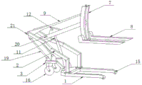
图1为一种便携式的手扶电动叉车的结构示意图。FIG. 1 is a schematic structural diagram of a portable hand-held electric forklift.
图2为一种便携式的手扶电动叉车在升起状态下的结构示意图。FIG. 2 is a schematic structural diagram of a portable hand-held electric forklift in a raised state.
图3为一种便携式的手扶电动叉车的结构示意图。FIG. 3 is a schematic structural diagram of a portable hand-held electric forklift.
图中标号:1、车架;2、斜梁;3、横梁;4、第一连接杆;5、第二连接杆;6、起重臂;7、前叉立梁;8、前叉;9、平衡拉杆;10、油缸;11、伸缩杆;12、拉称;13、连接轴;14、长条孔;15、第一脚轮;16、第二脚轮;17、蓄电池;18、控制开关;19、支撑杆;20、限位开关;21、扶手。Labels in the figure: 1, frame; 2, inclined beam; 3, beam; 4, first connecting rod; 5, second connecting rod; 6, boom; 7, front fork vertical beam; 8, front fork; 9. Balance rod; 10. Oil cylinder; 11. Telescopic rod; 12. Pull scale; 13. Connecting shaft; 14. Long hole; 15. First caster; 16. Second caster; 17. Battery; 18. Control switch ; 19, support rod; 20, limit switch; 21, armrest.
具体实施方式Detailed ways
下面结合附图和实施例对本申请作进一步的详细说明。可以理解的是,此处所描述的具体实施例仅仅用于解释相关发明,而非对该发明的限定。另外还需要说明的是,为了便于描述,附图中仅示出了与发明相关的部分。The present application will be further described in detail below with reference to the accompanying drawings and embodiments. It should be understood that the specific embodiments described herein are only used to explain the related invention, but not to limit the invention. In addition, it should be noted that, for the convenience of description, only the parts related to the invention are shown in the drawings.
需要说明的是,在不冲突的情况下,本申请中的实施例及实施例中的特征可以相互组合。下面将参考附图并结合实施例来详细说明本申请。It should be noted that the embodiments in the present application and the features of the embodiments may be combined with each other in the case of no conflict. The present application will be described in detail below with reference to the accompanying drawings and in conjunction with the embodiments.
实施例一Example 1
请参考图1、图2和图3所示的本申请提供的一种便携式的手扶电动叉车的第一种实施例的结构示意图,包括:第一车架和设置在所述第一车架上的第二车架;Please refer to FIG. 1 , FIG. 2 and FIG. 3 , which are schematic structural diagrams of a first embodiment of a portable hand-held electric forklift provided by the present application, including: a first frame and a on the second frame;
所述第一车架包括:车架1和两个平行设置的斜梁2;所述车架1呈U型结构,所述车架1设置有两个平行设置的前叉腿;每个所述前叉腿的端部设置有第一脚轮15;所述车架1远离所述前叉腿的一侧设置有两个平行设置的横梁3;所述横梁3的端部设置有第二脚轮16;两个所述斜梁2之间设置有平行设置的第一连接杆4与第二连接杆5,且所述第二连接杆5位于两个所述斜梁2的端部;The first frame includes: a
所述第二车架包括:起重臂6和前叉立梁7;所述起重臂6设置在所述第一连接杆4上,且所述起重臂6连接有驱动组件;所述前叉立梁7固接在所述起重臂6的端部;所述前叉立梁7上设置有前叉8;所述前叉立梁7与所述第二连接杆5之间设有平衡拉杆9;所述平衡拉杆9分别与所述前叉立梁7、所述第二连接杆5可旋转连接;所述起重臂6上还开设有长条孔14;所述长条孔14的边沿设置有两个对称设置的拉称12;两个所述拉称12之间设置有连接轴13。The second frame includes: a
在本实施例中,车架1呈U型结构,作为本叉车的承载基座,用于安装能够相对第一车架移动的第二车架;In this embodiment, the
两个斜梁2,平行设置在所述车架1的表面,对货物起到支撑的作用,此外,所述斜梁2与所述车架1的前叉腿形成的角度大于或等于90度,能够分散起重臂6所承受的力,避免起重臂6被压断;Two
第一脚轮15,设置在所述前叉腿的端部,便于本叉车的移动;两个横梁3,平行设置在所述车架1远离所述前叉腿的一侧,用于安装第二脚轮16,也起到支撑、便于移动的效果;The
第二脚轮16,设置在横梁3的端部,第一脚轮15与第二脚轮16配合使用,起到便于移动本叉车的效果,此处,第二脚轮16采用万向轮,实现本叉车在移动时方便转弯的效果;The
第一连接杆4与第二连接杆5,设置在两个所述斜梁2之间,二者平行设置,且所述第二连接杆5位于两个所述斜梁2的端部,第一连接杆4用于安装起重臂6,第二连接杆5用于安装平衡拉杆9;The first connecting
起重臂6,设置在所述第一连接杆4上,用于将待搬运的货物进行升降,此处,起重臂6采用直臂或者曲臂均能够实现对待搬运货物的升降过程;The
前叉立梁7,设置在所述起重臂6的端部,用于安装前叉8;前叉8,设置在所述前叉立梁7上,用于承载待搬运的货物;The front fork
平衡拉杆9,设置在所述前叉立梁7与所述第二连接杆5之间,其分别与前叉立梁7、第二连接杆5可旋转连接,用于保持前叉立梁7的平衡稳定性,同时也能够为起重臂6分担重力,当驱动组件启动使得起重臂6靠近第一车架的一端围绕第一连接杆4旋转,同时,平衡拉杆9绕着所述第二连接杆5旋转,故平衡拉杆9不会妨碍起重臂6的提升作业过程,此外,平衡拉杆9的连接方式,还可以是在两个斜梁2的端部安装一个连接架,将平衡拉杆9的两端分别与连接架、前叉立梁7可旋转连接,此连接架还能够用作扶手和安装控制开关;The
长条孔14,设置在所述起重臂6上,用于伸缩杆11穿过,此处,长条孔14的截面形状还可选用圆形或者正方形等形状;The
两个拉称12,对称设置在所述长条孔14的边沿,二者之间设置有连接轴13,用于固定伸缩杆11,实现油缸10控制起重臂6升降的作用,同时拉称12还有分担起重臂6重力的作用,避免起重臂6承受的重力过大,出现折断的问题,此处,拉称12的形状不加以限定,可选地,三角形、正方形、长方形或者异形形状等。Two pull scales 12 are symmetrically arranged on the edge of the
在任一优选的实施例中,所述驱动组件包括:油缸10和蓄电池17;所述油缸10设置在所述车架1上,且所述油缸10位于两个所述第二支撑杆3之间;所述油缸10的活塞杆固接有伸缩杆11,且所述伸缩杆11的端部贯穿所述长条孔14固接在所述连接轴13上;所述蓄电池17能够设置在任一所述斜梁2的侧壁上、所述车架1的表面或者所述车架1靠近所述横梁3的侧壁上;每个所述斜梁2的外壁上设置有扶手21,所述扶手21靠近所述斜梁2的端部,且两个所述扶手21对称设置;任一所述斜梁2的端部还设置有控制开关18,且所述控制开关18与所述扶手21相邻设置;所述蓄电池17通过导线分别与所述油缸10、所述控制开关18连接。In any preferred embodiment, the drive assembly includes: an
在本实施例中,油缸10,设置在所述车架1上,所述油缸10位于两个所述第二支撑杆3之间,且其活塞杆固接有伸缩杆11,为起重臂6的升降提供驱动力,油缸10的类型,例如为TKC MOB40*200-TC,当油缸10启动,使得起重臂6靠近第一车架的一端围绕第一连接杆4旋转且起重臂6相对远离第一连接杆4的一端将第二车架提升,以将第二车架上的待搬运的货物提升;蓄电池17,设置在任一所述斜梁2的侧壁上、所述车架1的表面或者所述车架1靠近所述横梁3的侧壁上,用于为油缸10提供电能,蓄电池的型号,例如为48V 12ah电池;扶手21,设置在每个所述斜梁2的外壁上,其靠近所述斜梁2的端部,且两个扶手21对称设置,便于操作人员推动本叉车,此处,扶手21还能够设置在斜梁2的端部,同样能够达到便于推动、操作本叉车的作用;控制开关18,设置在任一所述斜梁2的端部,且其与所述扶手21相邻设置,操作人员在握住扶手的同时就能够操作控制开关18的开启或关闭,所述蓄电池17通过导线分别与所述油缸10、所述控制开关18连接,通过控制开关18控制油缸的开启闭合,以控制本叉车的工作状态。In this embodiment, the
在任一优选的实施例中,所述斜梁2与所述横梁3之间设置有支撑杆19。In any preferred embodiment, a
在本实施例中,支撑杆19,设置在所述斜梁2与所述横梁3之间,增强斜梁2的支撑效果,避免斜梁2被重量大的货物压断,对本装置造成损坏。In this embodiment, the
在任一优选的实施例中,所述支撑杆19的两端分别可拆卸地与所述斜梁2、所述横梁3连接。In any preferred embodiment, both ends of the
在本实施例中,支撑杆19的两端分别与斜梁2和横梁3的连接方式,此处不加以限定,可选地,螺栓连接,具体连接方式:通过螺栓将支撑杆19的两端分别与斜梁2和横梁3连接,便于更换支撑杆19,根据承载货物的重量不同,选择安装合适的支撑杆19,以保证支撑的效果。In this embodiment, the two ends of the
在任一优选的实施例中,所述起重臂6上设置有限位开关20,且所述限位开关20靠近所述第一连接杆4设置。In any preferred embodiment, a
在本实施例中,限位开关20,设置在所述起重臂6上,且其靠近所述第一连接杆4设置,用于限定起重臂6的升起高度,使得起重臂6运动到设定的位置能够停止运动,以实现保护起重臂6的作用,此处,限位开关20的型号,例如为STEIMEX LSA-012型限位开关。In this embodiment, the
具体工作过程如下:The specific working process is as follows:
首先将充满电量的蓄电池17安装在斜梁2上,将整个叉车移动到待搬运货物的指定位置,然后操作人员启动控制开关18,使得蓄电池17对油缸10进行供电,驱动油缸10输出端抬起起重臂6,起重臂6带动前叉立梁7向上运动,前叉立梁7在上升过程中,受平衡拉杆9两端的作用力,确保前叉立梁7上升过程中保持平衡,由于前叉立梁7与前叉8之间为刚性连接,前叉立梁7的上升过程即是前叉8的上升过程,进而叉取并搬运货物,待卸货时,操作人员握住扶手21即可将本叉车推到指定的位置,启动控制开关18,使得起重臂6降下,进而实现前叉力梁7和前叉8下降,将货物卸在指定位置,完成整个装卸过程。First, install the fully charged
以上描述仅为本申请的较佳实施例以及对所运用技术原理的说明。本领域技术人员应当理解,本申请中所涉及的发明范围,并不限于上述技术特征的特定组合而成的技术方案,同时也应涵盖在不脱离所述发明构思的情况下,由上述技术特征或其等同特征进行任意组合而形成的其它技术方案。例如上述特征与本申请中公开的(但不限于)具有类似功能的技术特征进行互相替换而形成的技术方案。The above description is only a preferred embodiment of the present application and an illustration of the applied technical principles. Those skilled in the art should understand that the scope of the invention involved in this application is not limited to the technical solution formed by the specific combination of the above-mentioned technical features, and should also cover the above-mentioned technical features without departing from the inventive concept. Other technical solutions formed by any combination of its equivalent features. For example, a technical solution is formed by replacing the above-mentioned features with the technical features disclosed in this application (but not limited to) with similar functions.
Claims (7)
Applications Claiming Priority (2)
| Application Number | Priority Date | Filing Date | Title |
|---|---|---|---|
| CN201920927177 | 2019-06-19 | ||
| CN2019209271774 | 2019-06-19 |
Publications (2)
| Publication Number | Publication Date |
|---|---|
| CN111517246A true CN111517246A (en) | 2020-08-11 |
| CN111517246B CN111517246B (en) | 2025-08-15 |
Family
ID=71901593
Family Applications (2)
| Application Number | Title | Priority Date | Filing Date |
|---|---|---|---|
| CN202010297914.4A Active CN111517246B (en) | 2019-06-19 | 2020-04-16 | Portable hand electric fork-lift |
| CN202020561867.5U Active CN212832614U (en) | 2019-06-19 | 2020-04-16 | Portable hand electric fork-lift |
Family Applications After (1)
| Application Number | Title | Priority Date | Filing Date |
|---|---|---|---|
| CN202020561867.5U Active CN212832614U (en) | 2019-06-19 | 2020-04-16 | Portable hand electric fork-lift |
Country Status (1)
| Country | Link |
|---|---|
| CN (2) | CN111517246B (en) |
Cited By (1)
| Publication number | Priority date | Publication date | Assignee | Title |
|---|---|---|---|---|
| CN112645247A (en) * | 2020-12-29 | 2021-04-13 | 智捷智能科技香河有限公司 | Novel forklift |
Families Citing this family (1)
| Publication number | Priority date | Publication date | Assignee | Title |
|---|---|---|---|---|
| CN111517246B (en) * | 2019-06-19 | 2025-08-15 | 王静 | Portable hand electric fork-lift |
Citations (8)
| Publication number | Priority date | Publication date | Assignee | Title |
|---|---|---|---|---|
| GB1491422A (en) * | 1975-01-21 | 1977-11-09 | Kooi Bv | Fork-lift truck |
| DE10123991A1 (en) * | 2001-05-17 | 2002-12-05 | Peter Claus Ritzenhoff | Hand operated stacker truck has support frame running on wheels or rollers, tined fork, chassis, shaft and drive mechanism |
| CN103708384A (en) * | 2012-10-09 | 2014-04-09 | 兴化东华齿轮有限公司 | Feeding forklift |
| CN105060176A (en) * | 2015-07-29 | 2015-11-18 | 庞桂福 | Stacking car driven by mini-tiller |
| CN108455487A (en) * | 2018-03-16 | 2018-08-28 | 王静 | A kind of hand steered hydraulic pressure handling device and its application method |
| CN109292682A (en) * | 2018-09-20 | 2019-02-01 | 安徽工程大学 | Power-assisted manual forklift based on lever principle |
| CN208577387U (en) * | 2018-04-27 | 2019-03-05 | 四川成康动物药业有限公司 | Cargo carrying small-sized fork truck |
| CN212832614U (en) * | 2019-06-19 | 2021-03-30 | 王静 | Portable hand electric fork-lift |
-
2020
- 2020-04-16 CN CN202010297914.4A patent/CN111517246B/en active Active
- 2020-04-16 CN CN202020561867.5U patent/CN212832614U/en active Active
Patent Citations (8)
| Publication number | Priority date | Publication date | Assignee | Title |
|---|---|---|---|---|
| GB1491422A (en) * | 1975-01-21 | 1977-11-09 | Kooi Bv | Fork-lift truck |
| DE10123991A1 (en) * | 2001-05-17 | 2002-12-05 | Peter Claus Ritzenhoff | Hand operated stacker truck has support frame running on wheels or rollers, tined fork, chassis, shaft and drive mechanism |
| CN103708384A (en) * | 2012-10-09 | 2014-04-09 | 兴化东华齿轮有限公司 | Feeding forklift |
| CN105060176A (en) * | 2015-07-29 | 2015-11-18 | 庞桂福 | Stacking car driven by mini-tiller |
| CN108455487A (en) * | 2018-03-16 | 2018-08-28 | 王静 | A kind of hand steered hydraulic pressure handling device and its application method |
| CN208577387U (en) * | 2018-04-27 | 2019-03-05 | 四川成康动物药业有限公司 | Cargo carrying small-sized fork truck |
| CN109292682A (en) * | 2018-09-20 | 2019-02-01 | 安徽工程大学 | Power-assisted manual forklift based on lever principle |
| CN212832614U (en) * | 2019-06-19 | 2021-03-30 | 王静 | Portable hand electric fork-lift |
Cited By (1)
| Publication number | Priority date | Publication date | Assignee | Title |
|---|---|---|---|---|
| CN112645247A (en) * | 2020-12-29 | 2021-04-13 | 智捷智能科技香河有限公司 | Novel forklift |
Also Published As
| Publication number | Publication date |
|---|---|
| CN212832614U (en) | 2021-03-30 |
| CN111517246B (en) | 2025-08-15 |
Similar Documents
| Publication | Publication Date | Title |
|---|---|---|
| CN102815546B (en) | Vehicle goods bracket and vehicle goods bracket assembly | |
| KR100984538B1 (en) | Cargo handling equipment | |
| CN203582406U (en) | Forklift with adjustable width | |
| CN111605592B (en) | Multifunctional crawler type automatic stair climbing truck | |
| CN207792613U (en) | The transporting forklift of Anti-fall | |
| CN212832614U (en) | Portable hand electric fork-lift | |
| CN220485245U (en) | Portable fork truck | |
| CN211169605U (en) | Hydraulic forklift loading and carrying line type intelligent small crane | |
| CN210973745U (en) | Transport vehicle | |
| CN209507499U (en) | A kind of side loader crane arm | |
| CN216549209U (en) | Unloading equipment for efficient logistics container | |
| CN101180193A (en) | Equipment for lifting, handling and transporting containers | |
| CN212374802U (en) | Stable in structure's hand fork truck | |
| JP2005179051A (en) | Transfer lifting truck | |
| CN210286531U (en) | Steel coil ferry railcar | |
| CN205855917U (en) | A kind of fork lift | |
| KR20130036871A (en) | The cargo-working used carrier | |
| KR102468543B1 (en) | Forklift for moving small and medium cargo | |
| CN217478996U (en) | Full remote control automatic loading and unloading transport vechicle | |
| CN105947906A (en) | Combined moving machine for improving efficiency and safety | |
| CN211001627U (en) | Trolley for logistics | |
| CN215048416U (en) | Novel forklift | |
| CN115159401A (en) | Ox-type forklift and using method thereof | |
| CN207468053U (en) | Full angle crane | |
| CN105752853B (en) | Port and pier cargo transportation device |
Legal Events
| Date | Code | Title | Description |
|---|---|---|---|
| PB01 | Publication | ||
| PB01 | Publication | ||
| SE01 | Entry into force of request for substantive examination | ||
| SE01 | Entry into force of request for substantive examination | ||
| GR01 | Patent grant | ||
| GR01 | Patent grant |