CN111495872B - Air knife mechanism with adjusting function - Google Patents
Air knife mechanism with adjusting function Download PDFInfo
- Publication number
- CN111495872B CN111495872B CN202010384954.2A CN202010384954A CN111495872B CN 111495872 B CN111495872 B CN 111495872B CN 202010384954 A CN202010384954 A CN 202010384954A CN 111495872 B CN111495872 B CN 111495872B
- Authority
- CN
- China
- Prior art keywords
- cavity
- air knife
- thread groove
- plate
- connecting frame
- Prior art date
- Legal status (The legal status is an assumption and is not a legal conclusion. Google has not performed a legal analysis and makes no representation as to the accuracy of the status listed.)
- Expired - Fee Related
Links
Images



Classifications
-
- B—PERFORMING OPERATIONS; TRANSPORTING
- B08—CLEANING
- B08B—CLEANING IN GENERAL; PREVENTION OF FOULING IN GENERAL
- B08B5/00—Cleaning by methods involving the use of air flow or gas flow
- B08B5/02—Cleaning by the force of jets, e.g. blowing-out cavities
-
- B—PERFORMING OPERATIONS; TRANSPORTING
- B08—CLEANING
- B08B—CLEANING IN GENERAL; PREVENTION OF FOULING IN GENERAL
- B08B13/00—Accessories or details of general applicability for machines or apparatus for cleaning
-
- F—MECHANICAL ENGINEERING; LIGHTING; HEATING; WEAPONS; BLASTING
- F26—DRYING
- F26B—DRYING SOLID MATERIALS OR OBJECTS BY REMOVING LIQUID THEREFROM
- F26B21/00—Arrangements for supplying or controlling air or other gases for drying solid materials or objects
- F26B21/001—Air generating units, e.g. movable or independent of drying enclosure
Landscapes
- Engineering & Computer Science (AREA)
- Mechanical Engineering (AREA)
- General Engineering & Computer Science (AREA)
- Harvester Elements (AREA)
Abstract
The invention discloses an air knife mechanism with an adjusting function, which comprises a base, wherein a supporting mechanism is fixedly arranged on the front surface of the base, a fixed frame is fixedly arranged at the top end of the base, a placing table is arranged at the top end of the fixed frame, an air knife body is arranged at the top end of the placing table, third connecting frames are arranged on two sides of the air knife body, a second connecting frame is fixedly arranged on the left side of the top end of the placing table, and a second connecting rod is movably arranged at the top end of the second connecting frame through a rotating shaft. According to the air knife body, the handle on the right side of the placing table is rotated, the second lead screw is stressed to rotate, so that the movable block which is matched with the third thread groove in a threaded mode on the second lead screw moves leftwards, when the first connecting frame moves leftwards, the right side of the air knife body is driven to move upwards, the angle of the air flow opening at the bottom end of the air knife body is adjusted, and therefore water is blown to objects with different height shapes, the operation is simple and convenient, and the practicability of the air knife body is greatly improved.
Description
Technical Field
The invention relates to the technical field of air knives, in particular to an air knife mechanism with an adjusting function.
Background
The air knife includes bar air knife and annular air knife, it is that a special design is used for blowing out powerful high-speed air current in order to blow off the dust, weather the water stain, cooling refrigerated equipment, the most lug weld of current air knife is on the production line, blow water to the article that need blow water on the production line, this has just resulted in when the article of needs to the co-altitude shape blows water, because can't adjust the angle of air knife air flow mouth, thereby be difficult to effectual article to co-altitude to blow water and handle, and then brought more inconvenience to staff's use, consequently need to design an air knife mechanism with regulatory function urgently.
Disclosure of Invention
The invention aims to provide an air knife mechanism with an adjusting function, and the air knife mechanism is used for solving the problems that in the background technology, most air knives are connected with a production line in a welding mode, the angle of an air flow port of each air knife cannot be adjusted, so that water blowing treatment is difficult to be effectively carried out on objects with different heights, and further, more inconvenience is brought to use of workers.
In order to achieve the purpose, the invention provides the following technical scheme: an air knife mechanism with an adjusting function comprises a base, wherein a supporting mechanism is fixedly installed on the front face of the base and comprises an installation block, a first thread groove, a screw rod, a rotary rod, a connecting plate and a rubber plate, the top end of the installation block is provided with the first thread groove, the screw rod is installed inside the first thread groove through threads, the rotary rod is fixedly installed at the top end of the screw rod, the connecting plate is fixedly installed at the bottom end of the rotary rod, the rubber plate is fixedly installed at the bottom end of the connecting plate, a fixing frame is fixedly installed at the top end of the base, a placing table is arranged at the top end of the fixing frame, a first cavity is formed in the top end of the fixing frame, a first bevel gear is fixedly installed at the bottom end of the inner wall of the first cavity through a bearing, a second bevel gear is installed on the first bevel gear in a meshed mode, the inner side of the second bevel gear is fixedly provided with a rotating shaft, the right side of the rotating shaft movably extends to the outer side of the first cavity, the inner side of the first bevel gear is fixedly provided with a first screw rod, the top end of the first screw rod is fixedly connected with the top end of the inner wall of the first cavity through a bearing, a movable plate is sleeved on the first screw rod, the bottom end of the movable plate is provided with a second threaded groove, the second threaded groove is matched with the first screw rod, the top end of the second threaded groove is fixedly provided with two supporting rods, the top ends of the supporting rods all extend to the outer side of the fixed frame, the top ends of the supporting rods are all fixedly connected with the bottom end of the placing table, the top end of the placing table is provided with an air knife body, the two sides of the air knife body are both provided with third connecting frames, the left side of the top end of the placing table is fixedly provided with a second connecting frame, and the top, one side, away from the second connecting frame, of the second connecting rod is movably connected with a left third connecting frame through a rotating shaft, a third cavity is formed in the right side of the placing table, a second lead screw is inserted into the third cavity, the left end of the second lead screw is fixedly connected with the left side of the inner wall of the third cavity through a bearing, a movable block is sleeved on the second lead screw, a third threaded groove is formed in the right side of the movable block, the third threaded groove is matched with the second lead screw, a first connecting frame is fixedly installed at the top end of the movable block, a first connecting rod is movably installed on the first connecting frame through the rotating shaft, one end, away from the first connecting frame, of the first connecting rod is movably connected with the right third connecting frame through the rotating shaft, fixed blocks are fixedly installed on two sides of the air knife body, and slots are formed in one sides, away from each other, of the fixed blocks, the one end that the third link is close to each other all inserts in the inside of slot, first spacing thread groove has all been seted up to the top and the bottom of the inboard third link of slot, the second spacing thread groove has all been seted up to the top and the bottom of fixed block, and the second spacing thread groove all is linked together with the slot, spacing bolt is all installed through the screw thread in the inside of second spacing thread groove, and the end of inserting of spacing bolt all extends to the inside of first spacing thread groove.
Preferably, the fixing frames on two sides of the inner wall of the first cavity are internally provided with first sliding grooves, the first sliding grooves are internally provided with first sliding blocks in a sliding manner, and one sides of the first sliding blocks, which are close to each other, are fixedly connected with the movable plate.
Preferably, one side that first slider kept away from each other all has the gyro wheel through axis of rotation movable mounting, and the gyro wheel all laminates with first slider inner wall.
Preferably, the both sides of fly leaf bottom all fixed mounting have first swash plate, and first swash plate is opposite form, the equal fixed mounting in first cavity inner wall both sides of fly leaf bottom has the fixed plate, and the fixed plate is opposite form, the second cavity has all been seted up on the top of fixed plate, the equal fixed mounting in one side that the second cavity inner wall was kept away from each other has the spring telescopic link, the equal fixed mounting in one end that the spring telescopic link is close to each other has the second swash plate, and the second swash plate mutually supports with first swash plate.
Preferably, a second sliding groove is formed in the fixing plate at the bottom end of the inner wall of the second cavity, a second sliding block is slidably mounted inside the second sliding groove, and the top end of the second sliding block is fixedly connected with the top end of the second inclined plate.
Compared with the prior art, the invention has the beneficial effects that:
1. by arranging the second screw rod, the movable block, the third thread groove, the first connecting frame, the first connecting rod, the second connecting frame, the second connecting rod and the third connecting frame, the handle on the right side of the placing table can be rotated, at the moment, the second screw rod is forced to rotate, thereby the movable block on the second screw rod which is in threaded fit with the third thread groove moves leftwards, at this time, as the first connecting frame is movably connected with the first connecting rod through the rotating shaft, the first connecting rod is movably connected with the third connecting frame on the right side through the rotating shaft, the third connecting frame and the second connecting frame on the left side are movably connected with the second connecting rod through the rotating shaft, so that when the first connecting frame moves leftwards, the right side of the air knife body is driven to move upwards, thereby adjust the angle of the air current mouth of air knife body bottom to blow water to the article of different height shapes, easy operation is convenient, has promoted the practicality of this device greatly.
2. Through being provided with first bevel gear, second bevel gear, first lead screw, the fly leaf, second thread groove and bracing piece, make the handle on the rotatory mount right side of accessible, at this moment, the inboard axis of rotation atress of second bevel gear rotates, thereby it is rotatory to drive second bevel gear, because second bevel gear and first bevel gear meshing, first bevel gear atress is rotatory and drive first lead screw rotatory, when first lead screw is rotatory, fly leaf through second thread groove screw-thread fit on the first lead screw is at first cavity rebound, thereby drive the bracing piece rebound, at this moment the fly leaf drives first slider and gyro wheel rebound in first spout, thereby adjust the distance of placing between platform and the ground, and then make the production line of the more height of this device suitability, and easy operation is convenient, the practicality of this device has been promoted greatly.
3. Through being provided with first swash plate, the fixed plate, the second cavity, spring telescopic link and second swash plate, make the height of placing the platform when staff's downward adjustment, make the fly leaf when the downstream to a certain position in first cavity, first swash plate inserts in the second cavity, because the shape intermeshing of first swash plate and second swash plate, consequently when first swash plate continues to insert, second swash plate atress extrusion spring telescopic link and inside shrink, reaction force when compressing through spring telescopic link is fixed with the laminating of second swash plate and first swash plate, at this moment the fly leaf is at first cavity internal fixation, thereby avoid because the fly leaf moves the range down too big, thereby contact with second bevel gear, and then cause the condition of device damage.
Drawings
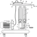
FIG. 1 is a schematic sectional elevation view of the structure of the present invention;
FIG. 2 is a schematic front view of the structure of the present invention;
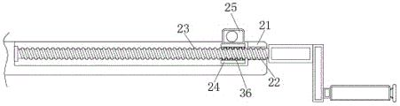
FIG. 3 is a schematic sectional front view of a partial structure of the placement table of the present invention;
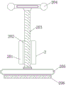
FIG. 4 is a schematic sectional front view of the supporting mechanism of the present invention;
FIG. 5 is an enlarged view of a portion of the structure at A in FIG. 1 according to the present invention;
fig. 6 is an enlarged view of a portion of the structure at B in fig. 1 according to the present invention.
In the figure: 1. a base; 2. a support mechanism; 201. mounting blocks; 202. a first thread groove; 203. a screw; 204. rotating the rod; 205. a connecting plate; 206. a rubber plate; 3. a fixed mount; 4. a first cavity; 5. a first bevel gear; 6. a second bevel gear; 7. a first lead screw; 8. a movable plate; 9. a second thread groove; 10. a support bar; 11. a first chute; 12. a first slider; 13. a roller; 14. a first sloping plate; 15. a fixing plate; 16. a second cavity; 17. a spring telescopic rod; 18. a second swash plate; 19. a second chute; 20. a second slider; 21. a placing table; 22. a third cavity; 23. a second lead screw; 24. a movable block; 25. a first connecting frame; 26. a first connecting rod; 27. a second link frame; 28. a second connecting rod; 29. a third connecting frame; 30. an air knife body; 31. a fixed block; 32. a slot; 33. a first limit thread groove; 34. a second limiting thread groove; 35. a limit bolt; 36. a third thread groove.
Detailed Description
The technical solutions in the embodiments of the present invention will be clearly and completely described below with reference to the drawings in the embodiments of the present invention, and it is obvious that the described embodiments are only a part of the embodiments of the present invention, and not all of the embodiments. All other embodiments, which can be derived by a person skilled in the art from the embodiments given herein without making any creative effort, shall fall within the protection scope of the present invention.
Referring to fig. 1-6, an embodiment of the present invention is shown:
an air knife mechanism with an adjusting function comprises a base 1, wherein a supporting mechanism 2 is fixedly arranged on the front surface of the base 1, the supporting mechanism 2 comprises a mounting block 201, a first thread groove 202, a screw rod 203, a rotating rod 204, a connecting plate 205 and a rubber plate 206, the top end of the mounting block 201 is provided with the first thread groove 202, the screw rod 203 is arranged in the first thread groove 202 through threads, the rotating rod 204 is fixedly arranged at the top end of the screw rod 203, the connecting plate 205 is fixedly arranged at the bottom end of the rotating rod 204, the rubber plate 206 is fixedly arranged at the bottom end of the connecting plate 205, the rotating rod 204 is screwed, the screw rod 203 is stressed to rotate, the screw rod 203 is in threaded fit with the first thread groove 202, the screw rod 203 moves downwards in the first thread groove 202 and drives the connecting plate 205 to move downwards, when the connecting plate 205 moves to a certain position, the rubber plate 206 is attached to the ground, and the, thereby the effectual vibrations that have reduced because the during operation produces etc. lead to this device to take place to remove or the skew condition that influences the device use, the effectual stability that has promoted this device during operation.
A fixed frame 3 is fixedly installed at the top end of a base 1, a placing table 21 is arranged at the top end of the fixed frame 3, a first cavity 4 is formed at the top end of the fixed frame 3, a first bevel gear 5 is fixedly installed at the bottom end of the inner wall of the first cavity 4 through a bearing, a second bevel gear 6 is installed on the first bevel gear 5 in a meshed mode, the right end of the second bevel gear 6 is fixedly connected with the right side of the inner wall of the first cavity 4 through a bearing, a rotating shaft is fixedly installed at the inner side of the second bevel gear 6, the right side of the rotating shaft movably extends to the outer side of the first cavity 4, a first lead screw 7 is fixedly installed at the inner side of the first bevel gear 5, the top end of the first lead screw 7 is fixedly connected with the top end of the inner wall of the first cavity 4 through a bearing, a movable plate 8 is sleeved on the first lead screw 7, a second thread groove 9 is formed at, and the number of the support rods 10 is two, the top ends of the support rods 10 extend to the outer side of the fixing frame 3, the top ends of the support rods 10 are fixedly connected with the bottom end of the placing table 21, by rotating the handle on the right side of the fixing frame 3, at this time, the rotating shaft on the inner side of the second bevel gear 6 is forced to rotate, so as to drive the second bevel gear 6 to rotate, because the second bevel gear 6 is meshed with the first bevel gear 5, the first bevel gear 5 is forced to rotate and drive the first screw rod 7 to rotate, when the first screw rod 7 rotates, the movable plate 8 on the first screw rod 7 in threaded fit with the second threaded groove 9 moves upwards in the first cavity 4, so as to drive the support rods 10 to move upwards, at this time, the movable plate 8 drives the first slide block 12 and the roller 13 to move upwards in the first sliding groove 11, so as to adjust the distance between the placing, and the operation is simple and convenient, and the practicability of the device is greatly improved.
All seted up first spout 11 in the mount 3 of first cavity 4 inner wall both sides, the inside all slidable mounting of first spout 11 has first slider 12, one side that first slider 12 is close to each other all with fly leaf 8 fixed connection, one side that first slider 12 kept away from each other all has gyro wheel 13 through axis of rotation movable mounting, and gyro wheel 13 all laminates with first slider 12 inner wall, when fly leaf 8 reciprocates in first cavity 4, because first slider 12 and fly leaf 8 fixed connection, consequently at this moment first slider 12 moves about in first spout 11, gyro wheel 13 laminates with first spout 11 inner wall, thereby effectual stability when having promoted fly leaf 8 and reciprocate.
The two sides of the bottom end of the movable plate 8 are fixedly provided with a first inclined plate 14, the first inclined plate 14 is opposite, the two sides of the inner wall of the first cavity 4 at the bottom end of the movable plate 8 are fixedly provided with a fixed plate 15, the fixed plates 15 are opposite, the top end of the fixed plate 15 is provided with a second cavity 16, one sides of the inner walls of the second cavity 16, which are far away from each other, are fixedly provided with a spring telescopic rod 17, one ends of the spring telescopic rods 17, which are close to each other, are fixedly provided with a second inclined plate 18, the second inclined plate 18 and the first inclined plate 14 are matched with each other, when a worker downwards adjusts the height of the placing table 21, so that when the movable plate 8 downwards moves to a certain position in the first cavity 4, the first inclined plate 14 is inserted into the second cavity 16, and because the shapes of the first inclined plate 14 and the second inclined plate 18 are meshed with each other, when the first inclined plate 14 is continuously, the second inclined plate 18 is attached and fixed with the first inclined plate 14 through the reaction force generated when the spring telescopic rod 17 is compressed, and at the moment, the movable plate 8 is fixed in the first cavity 4, so that the situation that the movable plate 8 is too large in downward movement range and is contacted with the second bevel gear 6 to damage the device is avoided.
All seted up second spout 19 in the fixed plate 15 of second cavity 16 inner wall bottom, the inside of second spout 19 all has slidable mounting second slider 20, the top of second slider 20 all with the top fixed connection of second swash plate 18, when first swash plate 14 moves down to a certain position and contact with second swash plate 18, disperse the pressure dispersion that first swash plate 14 applyed to second swash plate 18 and conduct to second slider 20 on, and promoted the stability of second swash plate 18 when moving about in second cavity 16.
The top end of the placing table 21 is provided with an air knife body 30, both sides of the air knife body 30 are provided with third connecting frames 29, the left side of the top end of the placing table 21 is fixedly provided with a second connecting frame 27, the top end of the second connecting frame 27 is movably provided with a second connecting rod 28 through a rotating shaft, one side of the second connecting rod 28 far away from the second connecting frame 27 is movably connected with the left third connecting frame 29 through a rotating shaft, the right side of the placing table 21 is provided with a third cavity 22, a second screw rod 23 is inserted into the third cavity 22, the left end of the second screw rod 23 is fixedly connected with the left side of the inner wall of the third cavity 22 through a bearing, the second screw rod 23 is sleeved with a movable block 24, the right side of the movable block 24 is provided with a third thread groove 36, the third thread groove 36 is matched with the second screw rod 23, the top end of the movable block 24 is fixedly provided with a first connecting frame 25, the first connecting rod 26 is movably arranged, one end of the first connecting rod 26, which is far away from the first connecting frame 25, is movably connected with the right third connecting frame 29 through a rotating shaft, both sides of the air knife body 30 are fixedly provided with fixing blocks 31, one sides, which are far away from each other, of the fixing blocks 31 are both provided with slots 32, one ends, which are close to each other, of the third connecting frames 29 are both inserted into the slots 32, the top end and the bottom end of the third connecting frame 29 inside the slots 32 are both provided with first limiting thread grooves 33, the top end and the bottom end of the fixing blocks 31 are both provided with second limiting thread grooves 34, the second limiting thread grooves 34 are both communicated with the slots 32, the inside of the second limiting thread grooves 34 are both provided with limiting bolts 35 through threads, and the insertion ends of the limiting bolts 35 extend into the first limiting thread grooves 33, when maintenance needs to be performed on the air knife body 30, the limiting bolts 35 are screwed, when the limiting bolts 35 are screwed, the insertion end of the limiting bolt 35 is no longer fixedly connected with the third connecting frame 29, and the air knife body 30 can be detached for maintenance by holding the third connecting frame 29 and pulling outwards to separate the third connecting frame 29 from the fixing block 31.
The air knife body 30 is conventional in the art, and the specific type thereof can be selected according to actual needs, and therefore will not be described herein.
The working principle is as follows: when the staff uses this device, at first transport this device to the use place through the universal wheel of base 1 bottom, with this device external power supply to for this device provides electric power support, at this moment through rotatory rotary rod 204, at this moment screw 203 atress is rotatory, because screw 203 and first thread groove 202 screw-thread fit, at this moment screw 203 moves down in first thread groove 202 to drive connecting plate 205 and move down, when connecting plate 205 removed to a certain position, rubber slab 206 laminated with ground.
By rotating the handle on the right side of the fixed frame 3, at this time, the rotating shaft on the inner side of the second bevel gear 6 is forced to rotate, so as to drive the second bevel gear 6 to rotate, because the second bevel gear 6 is meshed with the first bevel gear 5, the first bevel gear 5 is forced to rotate and drives the first screw rod 7 to rotate, when the first screw rod 7 rotates, the movable plate 8 which is in threaded fit with the first screw rod 7 through the second threaded groove 9 moves upwards in the first cavity 4, so as to drive the support rod 10 to move upwards, at this time, the movable plate 8 drives the first sliding block 12 and the roller 13 to move upwards in the first sliding groove 11, so that the distance between the placing table 21 and the ground is increased, when the placing table 21 is adjusted to a proper height, by rotating the handle on the right side of the placing table 21, at this time, the second screw rod 23 is forced to rotate, so as to cause the movable, at this time, since the first connecting frame 25 and the first connecting rod 26 are movably connected through the rotating shaft, the first connecting rod 26 and the right third connecting frame 29 are movably connected through the rotating shaft, and the left third connecting frame 29 and the second connecting frame 27 are movably connected with the second connecting rod 28 through the rotating shaft, when the first connecting frame 25 moves to the left, the right side of the air knife body 30 is driven to move upwards, so as to adjust the angle of the air flow opening at the bottom end of the air knife body 30, and when the angle is adjusted to a proper angle, the handle at the right side of the placing table 21 stops rotating, so that the device can be started by operating the operating panel at the front of the fixing frame 3, so as to blow water to the.
It will be evident to those skilled in the art that the invention is not limited to the details of the foregoing illustrative embodiments, and that the present invention may be embodied in other specific forms without departing from the spirit or essential attributes thereof. The present embodiments are therefore to be considered in all respects as illustrative and not restrictive, the scope of the invention being indicated by the appended claims rather than by the foregoing description, and all changes which come within the meaning and range of equivalency of the claims are therefore intended to be embraced therein. Any reference sign in a claim should not be construed as limiting the claim concerned.
Claims (5)
1. The utility model provides an air knife mechanism with regulatory function, includes base (1), its characterized in that: the front fixed mounting of base (1) has supporting mechanism (2), supporting mechanism (2) is including installation piece (201), first thread groove (202), screw rod (203), rotary rod (204), connecting plate (205) and rubber slab (206), first thread groove (202) have been seted up on the top of installation piece (201), screw rod (203) have been installed through the screw thread to the inside of first thread groove (202), the top fixed mounting of screw rod (203) has rotary rod (204), the bottom fixed mounting of rotary rod (204) has connecting plate (205), the bottom fixed mounting of connecting plate (205) has rubber slab (206), the top fixed mounting of base (1) has mount (3), the top of mount (3) is equipped with places platform (21), first cavity (4) have been seted up on the top of mount (3), the bottom end of the inner wall of the first cavity (4) is fixedly provided with a first bevel gear (5) through a bearing, the first bevel gear (5) is engaged with a second bevel gear (6), the right end of the second bevel gear (6) is fixedly connected with the right side of the inner wall of the first cavity (4) through a bearing, the inner side of the second bevel gear (6) is fixedly provided with a rotating shaft, the right side of the rotating shaft movably extends to the outer side of the first cavity (4), the inner side of the first bevel gear (5) is fixedly provided with a first lead screw (7), the top end of the first lead screw (7) is fixedly connected with the top end of the inner wall of the first cavity (4) through a bearing, the first lead screw (7) is sleeved with a movable plate (8), the bottom end of the movable plate (8) is provided with a second thread groove (9), and the second thread groove (9) is matched with the first, the top end of the second threaded groove (9) is fixedly provided with two support rods (10), the top ends of the support rods (10) extend to the outer side of the fixing frame (3), the top ends of the support rods (10) are fixedly connected with the bottom end of the placing table (21), the top end of the placing table (21) is provided with an air knife body (30), the two sides of the air knife body (30) are provided with third connecting frames (29), the left side of the top end of the placing table (21) is fixedly provided with a second connecting frame (27), the top end of the second connecting frame (27) is movably provided with a second connecting rod (28) through a rotating shaft, one side of the second connecting rod (28), which is far away from the second connecting frame (27), is movably connected with the left third connecting frame (29) through the rotating shaft, and the right side of the placing table (21) is provided with a third cavity (22), a second lead screw (23) is inserted into the third cavity (22), the left end of the second lead screw (23) is fixedly connected with the left side of the inner wall of the third cavity (22) through a bearing, a movable block (24) is sleeved on the second lead screw (23), a third thread groove (36) is formed in the right side of the movable block (24), the third thread groove (36) is matched with the second lead screw (23), a first connecting frame (25) is fixedly installed at the top end of the movable block (24), a first connecting rod (26) is movably installed on the first connecting frame (25) through a rotating shaft, one end, far away from the first connecting frame (25), of the first connecting rod (26) is movably connected with the third connecting frame (29) on the right side through the rotating shaft, fixed blocks (31) are fixedly installed on two sides of the air knife body (30), and slots (32) are formed in one sides, far away from each other, of the fixed blocks (31), the one end that third link (29) are close to each other all inserts in the inside of slot (32), first spacing thread groove (33) have all been seted up to the top and the bottom of the inboard third link (29) of slot (32), second spacing thread groove (34) have all been seted up to the top and the bottom of fixed block (31), and second spacing thread groove (34) all are linked together with slot (32), spacing bolt (35) are all installed through the screw in the inside of second spacing thread groove (34), and the end of inserting of spacing bolt (35) all extends to the inside of first spacing thread groove (33).
2. An air knife mechanism with adjustment function according to claim 1, characterized in that: first spout (11) have all been seted up in mount (3) of first cavity (4) inner wall both sides, the inside of first spout (11) all slidable mounting have first slider (12), one side that first slider (12) are close to each other all with fly leaf (8) fixed connection.
3. An air knife mechanism with adjustment function according to claim 2, characterized in that: one side that first slider (12) kept away from each other all has gyro wheel (13) through axis of rotation movable mounting, and gyro wheel (13) all with first slider (12) inner wall laminating.
4. An air knife mechanism with adjustment function according to claim 1, characterized in that: the utility model discloses a portable electronic device, including portable electronic device, fixed plate and fixed plate, the both sides of portable electronic device (8) bottom are all fixed mounting have first swash plate (14), and first swash plate (14) are opposite form, the first cavity (4) inner wall both sides of portable electronic device (8) bottom all fixed mounting have fixed plate (15), and fixed plate (15) are opposite form, second cavity (16) have all been seted up on the top of fixed plate (15), the one side that second cavity (16) inner wall was kept away from each other all fixed mounting have spring telescopic link (17), the one end that spring telescopic link (17) are close to each other all fixed mounting have second swash plate (18), and second swash plate (18) and first swash plate (14).
5. An air knife mechanism with adjustment function according to claim 4, characterized in that: second spout (19) have all been seted up in fixed plate (15) of second cavity (16) inner wall bottom, the inside of second spout (19) all slidable mounting has second slider (20), the top of second slider (20) all with the top fixed connection of second swash plate (18).
Priority Applications (1)
| Application Number | Priority Date | Filing Date | Title |
|---|---|---|---|
| CN202010384954.2A CN111495872B (en) | 2020-05-09 | 2020-05-09 | Air knife mechanism with adjusting function |
Applications Claiming Priority (1)
| Application Number | Priority Date | Filing Date | Title |
|---|---|---|---|
| CN202010384954.2A CN111495872B (en) | 2020-05-09 | 2020-05-09 | Air knife mechanism with adjusting function |
Publications (2)
| Publication Number | Publication Date |
|---|---|
| CN111495872A CN111495872A (en) | 2020-08-07 |
| CN111495872B true CN111495872B (en) | 2021-05-04 |
Family
ID=71865171
Family Applications (1)
| Application Number | Title | Priority Date | Filing Date |
|---|---|---|---|
| CN202010384954.2A Expired - Fee Related CN111495872B (en) | 2020-05-09 | 2020-05-09 | Air knife mechanism with adjusting function |
Country Status (1)
| Country | Link |
|---|---|
| CN (1) | CN111495872B (en) |
Families Citing this family (1)
| Publication number | Priority date | Publication date | Assignee | Title |
|---|---|---|---|---|
| CN115324989B (en) * | 2022-08-23 | 2025-08-05 | 韩国荣 | A hardware transfer connector with adjustable connection angle |
Citations (4)
| Publication number | Priority date | Publication date | Assignee | Title |
|---|---|---|---|---|
| CN204039479U (en) * | 2014-08-05 | 2014-12-24 | 甘肃酒钢集团宏兴钢铁股份有限公司 | An air knife online automatic cleaning device |
| CN109931531A (en) * | 2019-03-28 | 2019-06-25 | 宁波市丽得乐照明科技有限公司 | A kind of mobile LED lighting lamp device |
| CN209876395U (en) * | 2019-04-28 | 2019-12-31 | 国健创亿(北京)医疗科技有限公司 | Adjusting mechanism of medical image display device |
| CN110694384A (en) * | 2019-09-20 | 2020-01-17 | 湖州名洛科技有限公司 | A high-efficient dust pelletizing system for cup installation |
Family Cites Families (1)
| Publication number | Priority date | Publication date | Assignee | Title |
|---|---|---|---|---|
| US11097695B2 (en) * | 2018-10-30 | 2021-08-24 | Waymo Llc | Non-contact cleaning system |
-
2020
- 2020-05-09 CN CN202010384954.2A patent/CN111495872B/en not_active Expired - Fee Related
Patent Citations (4)
| Publication number | Priority date | Publication date | Assignee | Title |
|---|---|---|---|---|
| CN204039479U (en) * | 2014-08-05 | 2014-12-24 | 甘肃酒钢集团宏兴钢铁股份有限公司 | An air knife online automatic cleaning device |
| CN109931531A (en) * | 2019-03-28 | 2019-06-25 | 宁波市丽得乐照明科技有限公司 | A kind of mobile LED lighting lamp device |
| CN209876395U (en) * | 2019-04-28 | 2019-12-31 | 国健创亿(北京)医疗科技有限公司 | Adjusting mechanism of medical image display device |
| CN110694384A (en) * | 2019-09-20 | 2020-01-17 | 湖州名洛科技有限公司 | A high-efficient dust pelletizing system for cup installation |
Also Published As
| Publication number | Publication date |
|---|---|
| CN111495872A (en) | 2020-08-07 |
Similar Documents
| Publication | Publication Date | Title |
|---|---|---|
| CN208179709U (en) | A kind of effective drilling equipment of plastics | |
| CN111495872A (en) | Air knife mechanism with adjusting function | |
| CN207548366U (en) | A kind of wood board polishing machine | |
| CN214870909U (en) | A kind of insulation board slotting device | |
| CN209971512U (en) | Flash removing device of blow molding machine | |
| CN219085591U (en) | Engineering project construction management safety warning mechanism | |
| CN220491701U (en) | Fan base of dry-type transformer | |
| CN219772903U (en) | Auxiliary falling door jacking mechanism of dam crest door machine | |
| CN221215707U (en) | Quick-dismantling belt | |
| CN215698109U (en) | Machining drilling equipment | |
| CN216829840U (en) | Part overturning equipment for machining | |
| CN216028388U (en) | High-stability cutting device for aluminum profile machining | |
| CN212222794U (en) | Cutting device is used in glass board processing | |
| CN212330451U (en) | Special-shaped aluminum plate cutting machine convenient to adjust | |
| CN208513742U (en) | A cutting device for a slitting machine | |
| CN222289167U (en) | Laser machine body | |
| CN216399619U (en) | An easily adjustable storage rack for electronic product production | |
| CN218110132U (en) | Vertical machining center convenient to change guard gate | |
| CN210587447U (en) | Rotary cutting device is used in aluminum product processing | |
| CN217508928U (en) | Open-air high-pole camera of no power | |
| CN221774680U (en) | A foam sponge cutting device capable of collecting waste | |
| CN211464963U (en) | Milling device for metal product | |
| CN211640173U (en) | Paper tube fine cutting equipment with automatic discharging and sorting functions | |
| CN214024018U (en) | Plasma cutting dust remover | |
| CN221047454U (en) | Cutting device is used in cubical switchboard casing production |
Legal Events
| Date | Code | Title | Description |
|---|---|---|---|
| PB01 | Publication | ||
| PB01 | Publication | ||
| SE01 | Entry into force of request for substantive examination | ||
| SE01 | Entry into force of request for substantive examination | ||
| GR01 | Patent grant | ||
| GR01 | Patent grant | ||
| CF01 | Termination of patent right due to non-payment of annual fee | ||
| CF01 | Termination of patent right due to non-payment of annual fee |
Granted publication date: 20210504 |