CN111477501A - A Magnetic Retaining Operating Mechanism for Direct Opening of Microcomputer Protection Device - Google Patents
A Magnetic Retaining Operating Mechanism for Direct Opening of Microcomputer Protection Device Download PDFInfo
- Publication number
- CN111477501A CN111477501A CN201910066897.0A CN201910066897A CN111477501A CN 111477501 A CN111477501 A CN 111477501A CN 201910066897 A CN201910066897 A CN 201910066897A CN 111477501 A CN111477501 A CN 111477501A
- Authority
- CN
- China
- Prior art keywords
- magnetic
- cylindrical
- protection device
- excitation coil
- yoke
- Prior art date
- Legal status (The legal status is an assumption and is not a legal conclusion. Google has not performed a legal analysis and makes no representation as to the accuracy of the status listed.)
- Pending
Links
Images
Classifications
-
- H—ELECTRICITY
- H01—ELECTRIC ELEMENTS
- H01H—ELECTRIC SWITCHES; RELAYS; SELECTORS; EMERGENCY PROTECTIVE DEVICES
- H01H50/00—Details of electromagnetic relays
- H01H50/64—Driving arrangements between movable part of magnetic circuit and contact
- H01H50/641—Driving arrangements between movable part of magnetic circuit and contact intermediate part performing a rectilinear movement
-
- H—ELECTRICITY
- H01—ELECTRIC ELEMENTS
- H01H—ELECTRIC SWITCHES; RELAYS; SELECTORS; EMERGENCY PROTECTIVE DEVICES
- H01H51/00—Electromagnetic relays
- H01H51/01—Relays in which the armature is maintained in one position by a permanent magnet and freed by energisation of a coil producing an opposing magnetic field
Landscapes
- Physics & Mathematics (AREA)
- Electromagnetism (AREA)
- Electromagnets (AREA)
Abstract
本发明公布一种可以由微机保护装置直接驱动分闸的磁保持操动机构,由驱动轴、导向套、下绝磁板、圆柱形内磁轭、永磁体、励磁线圈、筒形外磁轭、垫圈、圆柱形动铁芯衔铁和上绝磁板组成,通过提高励磁线圈工作电压,减小励磁线圈体积,改善磁轭结构,减小导磁磁阻,按照特定工作参数绕制励磁线圈,可以满足微机保护装置保护输出驱动参数,实现微机保护装置直接驱动分闸,减少中高压断路器保护跳闸时间;还可以提高励磁线圈的线电阻,降低合闸驱动电流、饱和导通电流,降低励磁线圈发热损坏风险。
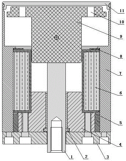
The invention discloses a magnetic holding operating mechanism that can be directly driven by a microcomputer protection device to open the gate. It is composed of a washer, a cylindrical moving iron core armature and an upper magnetic insulating plate. By increasing the working voltage of the excitation coil, reducing the volume of the excitation coil, improving the structure of the yoke and reducing the magnetic resistance, the excitation coil is wound according to specific working parameters. It can meet the protection output drive parameters of the microcomputer protection device, realize the direct drive opening of the microcomputer protection device, and reduce the protection trip time of the medium and high voltage circuit breaker; it can also increase the line resistance of the excitation coil, reduce the closing drive current, the saturation conduction current, and reduce the excitation. Risk of thermal damage to the coil.
Description
技术领域technical field
本发明涉及高、低压真空电器开关配件,特别是操动机构,属电器技术领域。The invention relates to high and low voltage vacuum electrical switch accessories, in particular to an operating mechanism, and belongs to the technical field of electrical appliances.
背景技术Background technique
当前电力输配电系统中,弹簧机构的断路器开关使用比较普遍。通过微机保护装置输出控制信号,驱动弹簧机构上的分励脱扣器,分励脱扣器动作释放储能弹簧的动力,驱动断路器分闸动作。从微机保护装置输出到断路器实现分闸,弹簧机构断路器开关需要相对较长的时间,不能适应较高的配网分级保护安排。近年来,永磁保持操动机构以其高可靠、长寿命、易控制等优点引起业内普遍关注,但是,永磁保持操动机构与其控制系统的配合问题一直困绕永磁保持操动机构的推广应用,永磁保持操动机构的组件虽然很少,却可构成多种磁路结构形式,不同形式磁路结构的永磁操动机构,在控制系统提供的电力作用下,执行高、低压真空开关状态转换的过程中,与时间相关的机、电、磁相互耦合的静态力学特性、动态力学特性及运动特性都存在很大差异,它直接影响着控制系统、操动机构与真空开关的匹配特性。目前永磁保持操动机构应用过程中,励磁线圈驱动电压采用DC110V或DC220V,为了在规定时间内输出足够的动力,励磁线圈线阻往往较小,这样带来一个弊端是:励磁线圈短路电流非常大,以至于在连续工作的情况下,励磁线圈严重发热,直至烧毁,也会出现控制系统电路元件因过流而烧坏。这种控制系统、励磁线圈易损坏现象,也严重影响了永磁保持操动机构的应用前景。In the current power transmission and distribution system, circuit breaker switches with spring mechanisms are commonly used. The control signal is output by the microcomputer protection device to drive the shunt release on the spring mechanism. The action of the shunt release releases the power of the energy storage spring and drives the circuit breaker to open. From the output of the microcomputer protection device to the opening of the circuit breaker, the spring mechanism circuit breaker switch requires a relatively long time, and cannot adapt to the higher distribution network grading protection arrangement. In recent years, the permanent magnet holding operating mechanism has attracted widespread attention in the industry due to its advantages of high reliability, long life, and easy control. Popularized and applied, although the components of the permanent magnet holding operating mechanism are few, they can form a variety of magnetic circuit structures. In the process of vacuum switch state transition, the static mechanical characteristics, dynamic mechanical characteristics and motion characteristics of the time-related mechanical, electrical and magnetic coupling are very different, which directly affect the control system, operating mechanism and vacuum switch. matching properties. At present, in the application process of the permanent magnet holding operating mechanism, the driving voltage of the excitation coil is DC110V or DC220V. In order to output enough power within the specified time, the line resistance of the excitation coil is often small, which brings a disadvantage: the short-circuit current of the excitation coil is very high. It is so large that in the case of continuous operation, the excitation coil is seriously heated until it is burned out, and the circuit components of the control system will also be burned out due to overcurrent. The control system and the excitation coil are easily damaged, which also seriously affects the application prospect of the permanent magnet holding operating mechanism.
发明内容SUMMARY OF THE INVENTION
为了解决目前弹簧机构断路器和永磁保持操动机构断路器应用过程中存在的问题,本发明公布了一种微机保护装置直接分闸的磁保持操动机构。通过提高励磁线圈工作电压,精准控制励磁线圈导通时间,减小励磁线圈线径,提高励磁线圈线电阻,缩小励磁线圈的外圈直径,优化磁路系统设计,降低导磁回路磁阻;与传统永磁操动机构相比较,在输出相同驱动力的条件下,该新型磁保持操动机构可以减少三分之一的体积,降低二分之一的励磁线圈峰值电流,可以减少过流、过热损坏风险;同时,降低驱动电流后,该新型磁保持操动机构可以通过微机保护装置直接驱动分闸,相较于弹簧机构,由微机保护装置直接驱动磁保持操动机构分闸,可以减少弹簧机构分励脱扣器动作时间,最终减少保护分闸时间,有利于输电配网分级保护安排。In order to solve the problems existing in the application process of the current spring mechanism circuit breaker and the permanent magnet holding operating mechanism circuit breaker, the present invention discloses a magnetic holding operating mechanism in which the microcomputer protection device is directly opened. By increasing the working voltage of the excitation coil, accurately controlling the conduction time of the excitation coil, reducing the wire diameter of the excitation coil, increasing the wire resistance of the excitation coil, reducing the diameter of the outer ring of the excitation coil, optimizing the design of the magnetic circuit system, and reducing the magnetic resistance of the magnetic conducting circuit; and Compared with the traditional permanent magnet operating mechanism, under the condition of outputting the same driving force, the new magnetic holding operating mechanism can reduce the volume by one-third, reduce the peak current of the excitation coil by one-half, and can reduce overcurrent, Risk of overheating damage; at the same time, after reducing the driving current, the new magnetic latching operating mechanism can directly drive the opening through the microcomputer protection device. Compared with the spring mechanism, the microcomputer protection device directly drives the magnetic latching operating mechanism to open, which can reduce The action time of the spring mechanism shunt release will ultimately reduce the protection opening time, which is beneficial to the hierarchical protection arrangement of the power transmission and distribution network.
永磁保持操动机构的工作过程是:励磁线圈正向加载一定时间的电源时,由励磁线圈产生的正向电磁场叠加永磁体的永磁场,通过导磁磁轭、工作气隙,使动铁芯衔铁产生拍合运动,输出合闸操动力,完成合闸动作,合闸后,由永磁体的永磁场通过导磁磁轭、动铁芯衔铁使拍合面保持吸力,输出合闸保持力,进入合闸状态;励磁线圈反向加载一定时间的电源时,由励磁线圈产生的反向电磁场消减永磁体的永磁场,拍合面保持吸力下降,达到临界点后,在外力的作用下,动铁芯衔铁与磁轭分离,完成分闸动作,进入分闸状态。The working process of the permanent magnet holding operating mechanism is: when the excitation coil is positively loaded with a power supply for a certain period of time, the positive electromagnetic field generated by the excitation coil superimposes the permanent magnet field of the permanent magnet, and the moving iron passes through the magnetic conductive yoke and the working air gap. The core armature generates the clap motion, outputs the closing operating force, and completes the closing action. After closing, the permanent magnet field of the permanent magnet passes through the magnetic conductive yoke and the moving iron core armature to maintain the suction force of the clap surface, and outputs the closing retention force. , enter the closing state; when the excitation coil is reversely loaded with the power supply for a certain period of time, the reverse electromagnetic field generated by the excitation coil reduces the permanent magnet field of the permanent magnet, and the suction force of the snap-fit surface decreases. After reaching the critical point, under the action of external force, The moving iron core armature is separated from the yoke to complete the opening action and enter the opening state.
励磁线圈匝数不变的情况下,减小导线直径可以减小励磁线圈外圈直径,可以提高励磁线圈的线电阻;提高励磁线圈的加载电压,可以使励磁线圈保持合适的安匝数,因此,励磁线圈具有最优参数。在保持导磁横截面面积不变的情况下,减小励磁线圈外圈直径可以减小外磁轭直径,减小导磁回路长度,即减小导磁回路磁阻,可以提高工作气隙的磁通,提高拍合面吸力。所以,合闸操动力和永磁场合闸保持力输出不变的情况下,不改变拍合面面积,适当减小外磁轭直径,减小导线直径,改善励磁线圈的工作参数,可以降低励磁线圈的过流损坏的风险。Under the condition that the number of turns of the excitation coil is unchanged, reducing the diameter of the wire can reduce the diameter of the outer circle of the excitation coil, which can increase the wire resistance of the excitation coil; increasing the loading voltage of the excitation coil can keep the excitation coil at a suitable number of ampere turns, so , the excitation coil has optimal parameters. Under the condition that the cross-sectional area of the magnetic permeability remains unchanged, reducing the diameter of the outer ring of the excitation coil can reduce the diameter of the outer magnetic yoke and the length of the magnetic conductive circuit, that is, reduce the magnetic resistance of the magnetic conductive circuit, which can improve the working air gap. Magnetic flux, improve the suction force of the clap surface. Therefore, under the condition that the closing actuation force and the output of the permanent magnet braking holding force remain unchanged, the area of the contact surface is not changed, the diameter of the outer yoke is appropriately reduced, the diameter of the wire is reduced, and the working parameters of the excitation coil are improved, which can reduce the excitation Risk of overcurrent damage to the coil.
本发明采取的技术方案为:The technical scheme adopted in the present invention is:
一种微机保护装置直接分闸的磁保持操动机构,包括驱动轴(1)、导向套(2)、下绝磁板(3)、圆柱形内磁轭(4)、永磁体(5)、励磁线圈(6)、筒形外磁轭(7)、垫圈(8)、圆柱形动铁芯衔铁(9)和上绝磁板(11)组成,永磁体(5)提供永久磁场源,由控制电路控制励磁线圈(6)电流及方向,产生正、反向瞬时电磁场与永磁场叠加,驱动圆柱形动铁芯衔铁(9),带动驱动轴(1),传递动力,完成分合闸动作和合闸永磁保持状态的转换;其中,圆柱形内磁轭(4)中心装入导向套(2),驱动轴(1)穿过导向套(2)、圆柱形内磁轭(4)和下绝磁板(3)中心;筒形外磁轭(7)由厚壁腔体和薄壁腔体两部份组成,筒形外磁轭(7)的厚壁腔体内依次装入垫圈(8)、励磁线圈(6)、圆柱形内磁轭(4)、永磁体(5)和导向套(2),筒形外磁轭(7)的薄壁腔体是圆柱形动铁芯衔铁(9)的上下运动空间,上绝磁板(11)和下绝磁板(3)固定在筒形外磁轭(7)的上下端面,组成一端封闭,一端有驱动轴(1)输出的操动机构整体。A magnetic holding operating mechanism for direct opening of a microcomputer protection device, comprising a drive shaft (1), a guide sleeve (2), a lower magnetic insulating plate (3), a cylindrical inner magnetic yoke (4), and a permanent magnet (5) , excitation coil (6), cylindrical outer yoke (7), washer (8), cylindrical moving iron core armature (9) and upper magnetic insulating plate (11), the permanent magnet (5) provides a permanent magnetic field source, The current and direction of the excitation coil (6) are controlled by the control circuit to generate positive and negative instantaneous electromagnetic fields and the superposition of the permanent magnetic field, drive the cylindrical moving iron core armature (9), drive the drive shaft (1), transmit power, and complete the opening and closing The conversion between the action and the closing permanent magnet holding state; wherein, the cylindrical inner yoke (4) is inserted into the guide sleeve (2) in the center, the drive shaft (1) passes through the guide sleeve (2), the cylindrical inner yoke (4) and the center of the lower magnetic insulating plate (3); the cylindrical outer yoke (7) is composed of two parts, a thick-walled cavity and a thin-walled cavity, and the thick-walled cavity of the cylindrical outer yoke (7) is filled with washers in turn. (8), excitation coil (6), cylindrical inner yoke (4), permanent magnet (5) and guide sleeve (2), the thin-walled cavity of the cylindrical outer yoke (7) is a cylindrical moving iron core The upper and lower movement space of the armature (9), the upper and lower magnetic insulating plates (11) and the lower magnetic insulating plates (3) are fixed on the upper and lower end faces of the cylindrical outer yoke (7), forming one end closed and one end with the output of the drive shaft (1) the operating mechanism as a whole.
所述励磁线圈(6)的分闸工作参数满足微机保护装置的输出控制参数,实现微机保护装置直接控制分闸;励磁线圈(6)的具体工作参数为:励磁线圈(6)两端,由储能电压在DC260V~DC450V之间的储能电容正向施加电源,持续30mS~80mS,所述微机保护装置直接分闸的磁保持操动机构可靠合闸,合闸电流在20A~100A之间,合闸响应时间不大于1mS,合闸动作时间30mS~80mS之间,励磁线圈(6)的短路电流不大于100A;励磁线圈(6)两端反向施加电压DC140V~DC450V时,励磁线圈(6)产生的反向电磁场使永磁保持失效,所述微机保护装置直接分闸的磁保持操动机构可靠分闸,分闸电流1A~5A,响应时间不大于1mS,分闸动作时间不大于20mS;励磁线圈(6)两端反向施加电压低于DC100V时,励磁线圈(6)产生的反向电磁场不能使永磁保持失效,所述微机保护装置直接分闸的磁保持操动机构可靠不分闸。一般情况下,微机保护装置保护动作输出可以提供电压DC220V或AC220V、电流不小于5A的驱动信号,因此,所述励磁线圈(6)工作参数可以满足微机保护装置动作输出参数要求,实现微机保护装置直接分闸。The opening working parameters of the excitation coil (6) meet the output control parameters of the microcomputer protection device, so that the microcomputer protection device can directly control the opening; the specific working parameters of the excitation coil (6) are: the two ends of the excitation coil (6) are connected by The energy storage capacitor with energy storage voltage between DC260V ~ DC450V applies power forward for 30mS ~ 80mS, the microcomputer protection device directly opens the magnetic latching operating mechanism to reliably close, and the closing current is between 20A ~ 100A , the closing response time is not more than 1mS, the closing action time is between 30mS and 80mS, and the short-circuit current of the excitation coil (6) is not more than 100A; when the reverse voltage of the excitation coil (6) is applied DC140V ~ DC450V, the excitation coil ( 6) The generated reverse electromagnetic field makes the permanent magnet hold invalid, and the magnetic hold operating mechanism of the microcomputer protection device is opened reliably, the opening current is 1A~5A, the response time is not more than 1mS, and the opening action time is not more than 20mS; when the reverse applied voltage at both ends of the excitation coil (6) is lower than DC100V, the reverse electromagnetic field generated by the excitation coil (6) cannot make the permanent magnet retention fail, and the magnetic retention operating mechanism of the microcomputer protection device directly opening is reliable Do not switch off. Under normal circumstances, the protection action output of the microcomputer protection device can provide a driving signal with a voltage of DC220V or AC220V and a current of not less than 5A. Therefore, the working parameters of the excitation coil (6) can meet the requirements of the action output parameters of the microcomputer protection device, and realize the microcomputer protection device. Open directly.
厚壁腔体和薄壁腔体在筒形外磁轭(7)的内壁形成台级分隔,在台级的厚壁腔体侧边缘向腔体内还有一个凸台(14)。所述微机保护装置直接分闸的磁保持操动机构合闸状态时,安装驱动轴(1)的圆柱形动铁芯衔铁(9)的下端面与圆柱形内磁轭(4)的上端面形成拍合面(13);圆柱形动铁芯衔铁(9)上部具有“伞”形结构,圆柱形动铁芯衔铁(9)的“伞”形结构外缘下横截面与筒形外磁轭(7)内壁的台级横截面形成拍合面(12),永磁体(5)产生的永久磁场通过导磁体筒形外磁轭(7)厚壁、圆柱形动铁芯衔铁(9)、圆柱形内磁轭(4)和拍合面(12)、拍合面(13)形成磁回路;在筒形外磁轭(7)厚壁腔体台级边缘上的凸台(14)可以增加导磁体的导磁截面积和拍合面(12)的面积,降低磁阻,增加磁通量,提高永磁体(5)产生的保持力。The thick-walled cavity and the thin-walled cavity form a stage-level separation on the inner wall of the cylindrical outer magnetic yoke (7), and there is a boss (14) on the side edge of the stage-level thick-walled cavity into the cavity. When the magnetic holding operating mechanism of the microcomputer protection device for direct opening is in the closed state, the lower end face of the cylindrical moving iron core armature (9) on which the drive shaft (1) is installed and the upper end face of the cylindrical inner magnetic yoke (4) Form a snap surface (13); the upper part of the cylindrical moving iron core armature (9) has an "umbrella"-shaped structure, and the lower cross section of the outer edge of the "umbrella"-shaped structure of the cylindrical moving iron core armature (9) is connected to the cylindrical outer magnetic The stage-level cross-section of the inner wall of the yoke (7) forms a snap surface (12), and the permanent magnetic field generated by the permanent magnet (5) passes through the magnetic conductor cylindrical outer yoke (7), which is a thick-walled, cylindrical moving iron core armature (9). , the cylindrical inner yoke (4) and the snap surface (12) and the snap surface (13) form a magnetic circuit; the boss (14) on the edge of the thick-walled cavity of the cylindrical outer yoke (7) The magnetic conductive cross-sectional area of the magnetic conductive body and the area of the snap-fit surface (12) can be increased, the magnetic resistance can be reduced, the magnetic flux can be increased, and the holding force generated by the permanent magnet (5) can be improved.
所述安装驱动轴(1)的圆柱形动铁芯衔铁(9)是一个运动整体,驱动轴(1)的上下两端均有中心锥形孔(16),圆柱形动铁芯衔铁(9)上部“伞”形结构外柱面有直角凹形台级(15),其圆柱面与驱动轴(1)端面的锥形孔同心,以保证驱动轴(1)和圆柱形动铁芯衔铁(9)的加工一致性。The cylindrical moving iron core armature (9) on which the drive shaft (1) is installed is a moving whole, the upper and lower ends of the drive shaft (1) are provided with a central conical hole (16), and the cylindrical moving iron core armature (9) ) The outer cylindrical surface of the upper "umbrella"-shaped structure has a right-angle concave stage (15), and its cylindrical surface is concentric with the tapered hole on the end face of the drive shaft (1) to ensure that the drive shaft (1) and the cylindrical moving iron core armature (9) Processing consistency.
附图说明Description of drawings
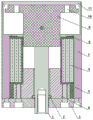
图1一种微机保护装置直接分闸的磁保持操动机构分闸状态。Fig. 1 is the open state of the magnetic holding operating mechanism of the direct opening of the microcomputer protection device.
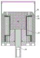
图2一种微机保护装置直接分闸的磁保持操动机构合闸状态。Fig. 2 is the closed state of the magnetic holding operating mechanism of the direct opening of the microcomputer protection device.
具体实施方式Detailed ways
对照图1一种微机保护装置直接分闸的磁保持操动机构,包括驱动轴(1)、导向套(2)、下绝磁板(3)、圆柱形内磁轭(4)、永磁体(5)、励磁线圈(6)、筒形外磁轭(7)、垫圈(8)、圆柱形动铁芯衔铁(9)和上绝磁板(11)组成,永磁体(5)提供永久磁场源,由控制电路控制励磁线圈(6)电流及方向,产生正、反向瞬时电磁场与永磁场叠加,驱动圆柱形动铁芯衔铁(9),带动驱动轴(1),传递动力,完成分合闸动作和合闸永磁保持状态的转换;其中,圆柱形内磁轭(4)中心装入导向套(2),驱动轴(1)穿过导向套(2)、圆柱形内磁轭(4)和下绝磁板(3)中心;筒形外磁轭(7)由厚壁腔体和薄壁腔体两部份组成,筒形外磁轭(7)的厚壁腔体内依次装入垫圈(8)、励磁线圈(6)、圆柱形内磁轭(4)、永磁体(5)和导向套(2),筒形外磁轭(7)的薄壁腔体是圆柱形动铁芯衔铁(9)的上下运动空间,上绝磁板(11)和下绝磁板(3)固定在筒形外磁轭(7)的上下端面,组成一端封闭,一端有驱动轴(1)输出的操动机构整体。In contrast to Figure 1, a magnetic holding operating mechanism for direct opening of a microcomputer protection device includes a drive shaft (1), a guide sleeve (2), a lower magnetic insulating plate (3), a cylindrical inner magnetic yoke (4), a permanent magnet (5), the excitation coil (6), the cylindrical outer yoke (7), the washer (8), the cylindrical moving iron core armature (9) and the upper magnetic insulating plate (11), the permanent magnet (5) provides permanent The magnetic field source is controlled by the control circuit to control the current and direction of the excitation coil (6) to generate positive and negative instantaneous electromagnetic fields and the superposition of the permanent magnetic field, drive the cylindrical moving iron core armature (9), drive the drive shaft (1), transmit power, and complete The switching of the opening and closing action and the closing permanent magnet holding state; wherein, the cylindrical inner yoke (4) is inserted into the guide sleeve (2) in the center, and the drive shaft (1) passes through the guide sleeve (2), the cylindrical inner yoke (4) and the center of the lower magnetic insulating plate (3); the cylindrical outer yoke (7) is composed of two parts: a thick-walled cavity and a thin-walled cavity, and the thick-walled cavity of the cylindrical outer yoke (7) is in turn. Load the washer (8), the excitation coil (6), the cylindrical inner yoke (4), the permanent magnet (5) and the guide sleeve (2), and the thin-walled cavity of the cylindrical outer yoke (7) is cylindrical The upper and lower moving space of the moving iron core armature (9), the upper and lower magnetic insulating plates (11) and the lower magnetic insulating plates (3) are fixed on the upper and lower end faces of the cylindrical outer magnetic yoke (7), forming a closed end and a drive shaft ( 1) The entire output operating mechanism.
所述励磁线圈(6)的线径采用1.0mm按780匝绕制,长度75mm、内径60mm、外径103mm,其工作参数为:励磁线圈(6)两端,由储能电压在DC260V~DC450V之间的储能电容正向施加电源,持续30mS~80mS,所述微机保护装置直接分闸的磁保持操动机构可靠合闸,合闸电流在20A~100A之间,合闸响应时间不大于1mS,合闸动作时间30mS~80mS之间,励磁线圈(6)的短路电流不大于100A;励磁线圈(6)两端反向施加电压DC140V~DC450V时,励磁线圈(6)产生的反向电磁场使永磁保持失效,所述微机保护装置直接分闸的磁保持操动机构可靠分闸,分闸电流1A~5A,响应时间不大于1mS,分闸动作时间不大于20mS;励磁线圈(6)两端反向施加电压低于DC100V时,励磁线圈(6)产生的反向电磁场不能使永磁保持失效,所述微机保护装置直接分闸的磁保持操动机构可靠不分闸。一般情况下,微机保护装置保护动作输出可以提供电压DC220V或AC220V、电流不小于5A的驱动信号,因此,所述励磁线圈(6)工作参数可以满足微机保护装置动作输出参数要求,实现微机保护装置直接分闸。The wire diameter of the excitation coil (6) is 1.0mm and wound by 780 turns, the length is 75mm, the inner diameter is 60mm, and the outer diameter is 103mm. The energy storage capacitor between the two is positively applied with power for 30mS~80mS, the magnetic latching operating mechanism of the microcomputer protection device is directly opened and closed reliably, the closing current is between 20A and 100A, and the closing response time is not more than 1mS, the closing action time is between 30mS and 80mS, the short-circuit current of the excitation coil (6) is not more than 100A; when the reverse voltage of DC140V~DC450V is applied to the two ends of the excitation coil (6), the reverse electromagnetic field generated by the excitation coil (6) To make the permanent magnet holding invalid, the magnetic holding operating mechanism of the microcomputer protection device directly opening the gate can reliably open the gate, the opening current is 1A-5A, the response time is not more than 1mS, and the opening action time is not more than 20mS; the excitation coil (6) When the reverse applied voltage at both ends is lower than DC100V, the reverse electromagnetic field generated by the excitation coil (6) cannot make the permanent magnet retention fail, and the magnetic retention operating mechanism of the microcomputer protection device directly opening is reliable and not opening. Under normal circumstances, the protection action output of the microcomputer protection device can provide a driving signal with a voltage of DC220V or AC220V and a current of not less than 5A. Therefore, the working parameters of the excitation coil (6) can meet the requirements of the action output parameters of the microcomputer protection device, and realize the microcomputer protection device. Open directly.
对照图2,厚壁腔体和薄壁腔体在筒形外磁轭(7)的内壁形成台级分隔,在台级的厚壁腔体侧边缘向腔体内还有一个凸台(14)。所述微机保护装置直接分闸的磁保持操动机构合闸状态时,安装驱动轴(1)的圆柱形动铁芯衔铁(9)的下端面与圆柱形内磁轭(4)的上端面形成拍合面(13);圆柱形动铁芯衔铁(9)上部具有“伞”形结构,圆柱形动铁芯衔铁(9)的“伞”形结构外缘下横截面与筒形外磁轭(7)内壁的台级横截面形成拍合面(12),永磁体(5)产生的永久磁场通过导磁体筒形外磁轭(7)厚壁、圆柱形动铁芯衔铁(9)、圆柱形内磁轭(4)和拍合面(12)、拍合面(13)形成磁回路;在筒形外磁轭(7)厚壁腔体台级边缘上的凸台(14)可以增加导磁体的导磁截面积和拍合面(12)的面积,降低磁阻,增加磁通量,提高永磁体产生的保持力。Referring to Figure 2, the thick-walled cavity and the thin-walled cavity form a stage-level separation on the inner wall of the cylindrical outer yoke (7), and there is a boss (14) on the side edge of the stage-level thick-walled cavity toward the cavity. . When the magnetic holding operating mechanism of the microcomputer protection device for direct opening is in the closed state, the lower end face of the cylindrical moving iron core armature (9) on which the drive shaft (1) is installed and the upper end face of the cylindrical inner magnetic yoke (4) Form a snap surface (13); the upper part of the cylindrical moving iron core armature (9) has an "umbrella"-shaped structure, and the lower cross section of the outer edge of the "umbrella"-shaped structure of the cylindrical moving iron core armature (9) is connected to the cylindrical outer magnetic The stage-level cross-section of the inner wall of the yoke (7) forms a snap surface (12), and the permanent magnetic field generated by the permanent magnet (5) passes through the magnetic conductor cylindrical outer yoke (7), which is a thick-walled, cylindrical moving iron core armature (9). , the cylindrical inner yoke (4) and the snap surface (12) and the snap surface (13) form a magnetic circuit; the boss (14) on the edge of the thick-walled cavity of the cylindrical outer yoke (7) The magnetic conductive cross-sectional area of the magnetic conductive body and the area of the snap-fit surface (12) can be increased, the magnetic resistance can be reduced, the magnetic flux can be increased, and the holding force generated by the permanent magnet can be improved.
所述安装驱动轴(1)的圆柱形动铁芯衔铁(9)是一个运动整体,驱动轴(1)的上下两端均有中心锥形孔(16),圆柱形动铁芯衔铁(9)上部“伞”形结构外柱面有直角凹形台级(15),其圆柱面与驱动轴(1)端面的锥形孔同心,以保证驱动轴(1)和圆柱形动铁芯衔铁(9)的加工一致性。The cylindrical moving iron core armature (9) on which the drive shaft (1) is installed is a moving whole, the upper and lower ends of the drive shaft (1) are provided with a central conical hole (16), and the cylindrical moving iron core armature (9) ) The outer cylindrical surface of the upper "umbrella"-shaped structure has a right-angle concave stage (15), and its cylindrical surface is concentric with the tapered hole on the end face of the drive shaft (1) to ensure that the drive shaft (1) and the cylindrical moving iron core armature (9) Processing consistency.
所述微机保护装置直接分闸的磁保持操动机构的工作过程是:励磁线圈(6)外接引线通过隔离开关分别连接外部驱动电路和微机保护装置的保护输出端口;在外部驱动电路的控制下,励磁线圈(6)正向加载时长30mS、电压300V的电源时,由励磁线圈(6)产生的正向电磁场叠加永磁体(5)的永磁场,通过导磁体筒形外磁轭(7)、圆柱形内磁轭(4)和圆柱形动铁芯衔铁(9),作用在上述导磁体之间的工作气隙,形成磁压降和作用力,导致圆柱形动铁芯衔铁(9)向圆柱形内磁轭(4)方向运动,即拍合运动,由驱动轴(1)输出合闸操动力,直致圆柱形动铁芯衔铁(9)下端面和和圆柱形内磁轭(4)上端面,圆柱形动铁芯衔铁(9)的“伞”形面和筒形外磁轭(7)内的台级面完全接触,即拍合面(12)和拍合面(13)完全接触,完成合闸动作;合闸后,由永磁体(5)的永磁场通过导磁体筒形外磁轭(7)、圆柱形内磁轭(4)和圆柱形动铁芯衔铁(9),使拍合面(12)和拍合面(13)保持吸力,由驱动轴(1)输出合闸保持力,进入合闸状态;由微机保护装置的保护输出端口或其他驱动电路输出控制,励磁线圈(6)反向加载电压DC200V的电源时,由励磁线圈(6)产生的反向电磁场消减永磁体(5)的永磁场,拍合面(12)和拍合面(13)保持吸力下降,达到临界点后,通过驱动轴(1),在外力的作用下,圆柱形动铁芯衔铁(9)与筒形外磁轭(7)、圆柱形内磁轭(4)分离,完成分闸动作,进入分闸状态。The working process of the magnetic holding operation mechanism of the microcomputer protection device directly opening is as follows: the external lead of the excitation coil (6) is respectively connected to the external drive circuit and the protection output port of the microcomputer protection device through the isolation switch; under the control of the external drive circuit , when the excitation coil (6) is positively loaded with a power supply with a duration of 30mS and a voltage of 300V, the positive electromagnetic field generated by the excitation coil (6) superimposes the permanent magnet field of the permanent magnet (5), and passes through the cylindrical outer yoke (7) of the magnetic conductor. , The cylindrical inner magnetic yoke (4) and the cylindrical moving iron core armature (9) act on the working air gap between the above-mentioned magnetic conductors to form a magnetic pressure drop and force, resulting in the cylindrical moving iron core armature (9) Moving in the direction of the cylindrical inner yoke (4), that is, the snap-fit movement, the closing actuating force is output by the drive shaft (1), and the lower end face of the cylindrical moving iron armature (9) and the cylindrical inner yoke ( 4) On the upper end face, the "umbrella" surface of the cylindrical moving iron core armature (9) is in complete contact with the stage surface in the cylindrical outer yoke (7), that is, the snap-fit surface (12) and the snap-fit surface (13) ) is completely contacted to complete the closing action; after closing, the permanent magnetic field of the permanent magnet (5) passes through the magnetic conductor cylindrical outer yoke (7), the cylindrical inner yoke (4) and the cylindrical moving iron core armature ( 9), to keep the suction force of the snap surface (12) and the snap surface (13), the closing force is output by the drive shaft (1), and the closing state is entered; it is output by the protection output port of the microcomputer protection device or other drive circuits. Control, when the excitation coil (6) is reversely loaded with a voltage DC200V power supply, the reverse electromagnetic field generated by the excitation coil (6) reduces the permanent magnet field of the permanent magnet (5), the snap-fit surface (12) and the snap-fit surface (13) Keep the suction force down, and after reaching the critical point, through the drive shaft (1), under the action of external force, the cylindrical moving iron core armature (9) is separated from the cylindrical outer yoke (7) and the cylindrical inner yoke (4) , to complete the opening action and enter the opening state.
所述微机保护装置直接分闸的磁保持操动机构应用于CBC1型10KV1600A分断31.5KA的断路器操动,按20秒间隔连续分合闸测试50000次,没有出现过热现象,也没有出现电流过流烧坏元件现象。The magnetic latching operating mechanism of the microcomputer protection device for direct opening is applied to the operation of the CBC1 type 10KV1600A 31.5KA circuit breaker, and the continuous opening and closing tests are performed 50,000 times at 20-second intervals, and there is no overheating phenomenon and no overcurrent. Flow burns out components.
Claims (5)
Priority Applications (1)
| Application Number | Priority Date | Filing Date | Title |
|---|---|---|---|
| CN201910066897.0A CN111477501A (en) | 2019-01-24 | 2019-01-24 | A Magnetic Retaining Operating Mechanism for Direct Opening of Microcomputer Protection Device |
Applications Claiming Priority (1)
| Application Number | Priority Date | Filing Date | Title |
|---|---|---|---|
| CN201910066897.0A CN111477501A (en) | 2019-01-24 | 2019-01-24 | A Magnetic Retaining Operating Mechanism for Direct Opening of Microcomputer Protection Device |
Publications (1)
| Publication Number | Publication Date |
|---|---|
| CN111477501A true CN111477501A (en) | 2020-07-31 |
Family
ID=71743884
Family Applications (1)
| Application Number | Title | Priority Date | Filing Date |
|---|---|---|---|
| CN201910066897.0A Pending CN111477501A (en) | 2019-01-24 | 2019-01-24 | A Magnetic Retaining Operating Mechanism for Direct Opening of Microcomputer Protection Device |
Country Status (1)
| Country | Link |
|---|---|
| CN (1) | CN111477501A (en) |
Cited By (3)
| Publication number | Priority date | Publication date | Assignee | Title |
|---|---|---|---|---|
| CN112614757A (en) * | 2020-12-07 | 2021-04-06 | 国网福建省电力有限公司检修分公司 | Breaker operating mechanism on-off state retaining device |
| CN114597097A (en) * | 2020-12-03 | 2022-06-07 | 华为技术有限公司 | a relay |
| CN116313580A (en) * | 2023-05-15 | 2023-06-23 | 深圳市国立智能电力科技有限公司 | Permanent magnet mechanism |
Citations (4)
| Publication number | Priority date | Publication date | Assignee | Title |
|---|---|---|---|---|
| CN102956397A (en) * | 2011-08-22 | 2013-03-06 | 吉林永大电气开关有限公司 | Permanent magnetic actuator with auxiliary electromagnetic loop |
| CN103295805A (en) * | 2012-02-29 | 2013-09-11 | 吉林永大电气开关有限公司 | Permanent-magnet operating mechanism with auxiliary electromagnetic circuit |
| CN104409236A (en) * | 2014-05-15 | 2015-03-11 | 苏艳刚 | A retaining force adjustable parallel permanent magnetic actuator |
| CN209401572U (en) * | 2019-01-24 | 2019-09-17 | 胡春生 | A kind of magnetic holding operating mechanism of the direct separating brake of microcomputer protecting device |
-
2019
- 2019-01-24 CN CN201910066897.0A patent/CN111477501A/en active Pending
Patent Citations (4)
| Publication number | Priority date | Publication date | Assignee | Title |
|---|---|---|---|---|
| CN102956397A (en) * | 2011-08-22 | 2013-03-06 | 吉林永大电气开关有限公司 | Permanent magnetic actuator with auxiliary electromagnetic loop |
| CN103295805A (en) * | 2012-02-29 | 2013-09-11 | 吉林永大电气开关有限公司 | Permanent-magnet operating mechanism with auxiliary electromagnetic circuit |
| CN104409236A (en) * | 2014-05-15 | 2015-03-11 | 苏艳刚 | A retaining force adjustable parallel permanent magnetic actuator |
| CN209401572U (en) * | 2019-01-24 | 2019-09-17 | 胡春生 | A kind of magnetic holding operating mechanism of the direct separating brake of microcomputer protecting device |
Cited By (6)
| Publication number | Priority date | Publication date | Assignee | Title |
|---|---|---|---|---|
| CN114597097A (en) * | 2020-12-03 | 2022-06-07 | 华为技术有限公司 | a relay |
| CN114597097B (en) * | 2020-12-03 | 2025-04-15 | 华为技术有限公司 | Relay |
| CN112614757A (en) * | 2020-12-07 | 2021-04-06 | 国网福建省电力有限公司检修分公司 | Breaker operating mechanism on-off state retaining device |
| CN112614757B (en) * | 2020-12-07 | 2023-10-10 | 国网福建省电力有限公司检修分公司 | A device for maintaining the opening and closing status of a circuit breaker operating mechanism |
| CN116313580A (en) * | 2023-05-15 | 2023-06-23 | 深圳市国立智能电力科技有限公司 | Permanent magnet mechanism |
| CN116313580B (en) * | 2023-05-15 | 2023-08-15 | 深圳市国立智能电力科技有限公司 | Permanent magnet mechanism |
Similar Documents
| Publication | Publication Date | Title |
|---|---|---|
| CN205069503U (en) | Monostable permanent magnetic mechanism and vacuum circuit breaker | |
| CN110634710A (en) | A permanent magnet contactor | |
| CN107146743B (en) | A kind of relay and its control circuit of the driving of bistable state Width funtion | |
| CN104347310B (en) | Permanent magnet spring mechanism switch of divided conductor power transmission line ice melting device | |
| WO2023056777A1 (en) | Energy-saving control method for contactor | |
| CN102931032B (en) | Low-voltage AC/DC control and protection electrical appliance | |
| CN109756158A (en) | A kind of circuit that quick band-type brake can be achieved | |
| CN105513844B (en) | Based on fault current energy and the quick electromagnetic tensile machine of change rate and its application | |
| CN201549396U (en) | Double contact structure for electric connection and relay thereof | |
| CN201387819Y (en) | Electric switch permanent magnet operating mechanism | |
| CN113936934A (en) | A rotary bistable permanent magnet operating mechanism and its working method | |
| CN201302946Y (en) | Permanent magnetic actuator for vacuum circuit breaker supplied with power by super capacitor | |
| CN205069539U (en) | Communication circuit breaker of good reliability | |
| CN109192617B (en) | Electromagnetic controllable attraction force is as alternating current contactor of twin coil structure of counter-force | |
| CN219696348U (en) | Relay magnetic circuit system for accelerating actuation and release | |
| CN110085487B (en) | Novel permanent-magnet electromagnetic relay | |
| WO2005004312A1 (en) | A micro-power consuming reciprocating device | |
| CN209401572U (en) | A kind of magnetic holding operating mechanism of the direct separating brake of microcomputer protecting device | |
| CN1319095C (en) | Asymmetric double coil type permanent-magnetic mechanism | |
| CN211173644U (en) | Door magnetic switch for household electrical appliance | |
| CN110853946B (en) | Double-magnetic-circuit direct-acting low-power-consumption permanent magnet brake-separating power-assisted electromagnetic mechanism | |
| CN204828878U (en) | Miniature pulsed electromagnetic valve | |
| CN115172116A (en) | Non-mechanical opening and closing electronic leakage circuit breaker | |
| CN104851749A (en) | Permanent magnetic contactor with switching-off protection function | |
| CN203288536U (en) | A novel permanent magnetic vacuum contactor |
Legal Events
| Date | Code | Title | Description |
|---|---|---|---|
| PB01 | Publication | ||
| PB01 | Publication | ||
| SE01 | Entry into force of request for substantive examination | ||
| SE01 | Entry into force of request for substantive examination | ||
| WD01 | Invention patent application deemed withdrawn after publication |
Application publication date: 20200731 |
|
| WD01 | Invention patent application deemed withdrawn after publication |