CN111457719B - Pyrolysis rotary kiln sealing device that floats - Google Patents
Pyrolysis rotary kiln sealing device that floats Download PDFInfo
- Publication number
- CN111457719B CN111457719B CN202010184697.8A CN202010184697A CN111457719B CN 111457719 B CN111457719 B CN 111457719B CN 202010184697 A CN202010184697 A CN 202010184697A CN 111457719 B CN111457719 B CN 111457719B
- Authority
- CN
- China
- Prior art keywords
- ring
- packing
- rotary kiln
- sealing seat
- gland
- Prior art date
- Legal status (The legal status is an assumption and is not a legal conclusion. Google has not performed a legal analysis and makes no representation as to the accuracy of the status listed.)
- Active
Links
- 238000007789 sealing Methods 0.000 title claims abstract description 91
- 238000000197 pyrolysis Methods 0.000 title claims abstract description 29
- 238000012856 packing Methods 0.000 claims abstract description 100
- 229910000639 Spring steel Inorganic materials 0.000 claims abstract description 57
- 229910000831 Steel Inorganic materials 0.000 claims abstract description 55
- 239000010959 steel Substances 0.000 claims abstract description 55
- 210000004907 gland Anatomy 0.000 claims abstract description 54
- 239000000835 fiber Substances 0.000 claims description 3
- 230000000694 effects Effects 0.000 abstract description 5
- 239000002360 explosive Substances 0.000 abstract description 5
- 239000007789 gas Substances 0.000 description 7
- 239000003245 coal Substances 0.000 description 5
- 230000005484 gravity Effects 0.000 description 5
- 238000000034 method Methods 0.000 description 5
- 150000001335 aliphatic alkanes Chemical class 0.000 description 2
- 239000003034 coal gas Substances 0.000 description 2
- 239000011280 coal tar Substances 0.000 description 2
- 230000006835 compression Effects 0.000 description 2
- 238000007906 compression Methods 0.000 description 2
- 238000006073 displacement reaction Methods 0.000 description 2
- 238000009434 installation Methods 0.000 description 2
- 230000009286 beneficial effect Effects 0.000 description 1
- 230000002457 bidirectional effect Effects 0.000 description 1
- 230000007547 defect Effects 0.000 description 1
- 238000007599 discharging Methods 0.000 description 1
- 238000012986 modification Methods 0.000 description 1
- 230000004048 modification Effects 0.000 description 1
- 239000000126 substance Substances 0.000 description 1
Images



Classifications
-
- F—MECHANICAL ENGINEERING; LIGHTING; HEATING; WEAPONS; BLASTING
- F27—FURNACES; KILNS; OVENS; RETORTS
- F27B—FURNACES, KILNS, OVENS OR RETORTS IN GENERAL; OPEN SINTERING OR LIKE APPARATUS
- F27B7/00—Rotary-drum furnaces, i.e. horizontal or slightly inclined
- F27B7/20—Details, accessories or equipment specially adapted for rotary-drum furnaces
- F27B7/22—Rotary drums; Supports therefor
- F27B7/24—Seals between rotary and stationary parts
Landscapes
- Engineering & Computer Science (AREA)
- Mechanical Engineering (AREA)
- General Engineering & Computer Science (AREA)
- Muffle Furnaces And Rotary Kilns (AREA)
Abstract
The invention discloses a pyrolysis rotary kiln floating sealing device which is arranged on the outer edge of a rotary kiln cylinder at the joint of the rotary kiln cylinder and a fixed cover shell; the device comprises a sealing seat ring, a gland, a spiral spring system, a packing, a plurality of spring steel sheets, a plurality of bolts, a plurality of screws, a plurality of nuts and a tensioning device; the sealing seat ring is arranged on the outer edge of the rotary kiln cylinder through an inner ring; the end parts of the sealing seat ring and the annular boss of the gland form an annular space on the outer edge of the rotary kiln cylinder; the spiral spring system connects the gland with the sealing seat ring; the packing is arranged in an annular space formed by a sealing seat ring and a gland on the outer edge of the rotary kiln cylinder; two ends of a steel wire rope of the tensioning device penetrate through the through holes and then are respectively arranged around the fixed pulley block. The pyrolysis rotary kiln floating sealing device is compact in structure, high in matching degree, remarkable in sealing effect, capable of meeting working condition factors such as radial runout, high temperature, positive pressure and flammable and explosive gas, and wide in application range.
Description
Technical Field
The invention relates to the technical field of coal chemical industry for preparing coal gas, tar and semicoke by low-temperature pyrolysis of low-order pulverized coal, in particular to a floating sealing device of a pyrolysis rotary kiln.
Background
The method for preparing coal gas, tar and semicoke by low-temperature pyrolysis of low-rank coal is a better way for clean utilization of low-rank coal, and overcomes the defects that low-rank coal is high in moisture content, easy to pulverize and high in volatility and cannot be directly utilized.
The pyrolysis rotary kiln cylinder is of a horizontal cylinder rotating structure, the diameter is generally 2-8 m, inflammable and explosive alkane gas is arranged in the cylinder, leakage is not allowed according to the sealing requirement between the rotating cylinder and the fixed discharging exhaust hood body, and the outer circle of the cylinder can periodically jump radially due to the roundness of the cylinder and deflection in the operation process; the gap between the fixed cover shell and the cylinder body is a leakage point. The temperature of alkane gas in the cylinder is higher, and is generally 500-900 ℃; the gas pressure inside the cylinder is usually micro positive pressure; therefore, the working condition factors such as radial run-out, high temperature, positive pressure, inflammable and explosive gases and the like put high requirements on the design of high-air-tightness sealing.
The existing packing is generally fixedly installed, the packing is installed in an annular space between a rotary cylinder and a sealed fixed cover shell, and the annular space is filled by the elasticity of the packing to ensure that no gap exists between the packing and the outer cylindrical surface of the rotary cylinder. When the structure is used for sealing a large-diameter rotary kiln, the roundness of the kiln barrel serving as a rotating shaft cannot be guaranteed, and the outer cylindrical surface of the rotary drum forms a cam effect of local radial runout in the rotating process, so that the packing seal cannot rebound in time, a gap is formed between the packing and the outer cylindrical surface of the rotary drum, and sealing gas leaks.
Disclosure of Invention
In order to solve the problems, the invention aims to provide a pyrolysis rotary kiln floating sealing device, which solves the problem of leakage between a fixed cover shell and a rotary kiln cylinder body caused by rebound of a packing of the sealing device and can adapt to working condition factors such as radial run-out, high temperature, positive pressure, flammable and explosive gas and the like of the rotary kiln cylinder body.
In order to achieve the purpose, the invention adopts the following technical scheme:
a pyrolysis rotary kiln floating sealing device is arranged on the outer edge of a rotary kiln cylinder at the joint of the rotary kiln cylinder and a fixed cover shell; the device comprises a sealing seat ring, a gland, a spiral spring system, a packing, a plurality of spring steel sheets, a plurality of bolts, a plurality of screws, a plurality of nuts and a tensioning device;
the sealing seat ring comprises an inner ring, an outer ring and a neck ring vertically arranged between the inner ring and the outer ring; the inner ring and the outer ring are of annular structures arranged in parallel, the outer diameters of the inner ring and the outer ring are the same, and the inner diameter of the outer ring is larger than that of the inner ring; the inner diameter of the inner ring is matched with the outer diameter of the rotary kiln cylinder; the diameter of the neck ring is the same as the inner diameter of the outer ring, one end of the neck ring is connected with the inner diameter of the outer ring, and the other end of the neck ring is arranged on the ring surface of the inner ring; the inner ring, the outer ring and the neck ring form a sealing seat ring with a double-ring surface structure with a circular groove in the middle; a fixed hole for installing the spring steel sheet is arranged on the ring surface of the neck ring; holes connected with the fixed cover shell are uniformly arranged on the ring surface of the inner ring; bolt mounting holes are uniformly formed in the ring surface of the outer ring; the sealing seat ring is arranged on the outer edge of the rotary kiln cylinder through an inner ring; a plurality of bolts respectively penetrate through holes on the ring surface of the inner ring, and the sealing seat ring is connected with the fixed cover shell through nuts;
the gland is of an annular structure with an annular boss in the middle, the outer diameter of the annular boss in the middle of the gland is matched with the inner diameter of the outer ring of the sealing seat ring, the gland is arranged on the outer edge of the rotary kiln barrel, and the end part of the annular boss of the gland is arranged in a circular groove of the sealing seat ring; through holes corresponding to the bolt mounting holes on the outer ring of the sealing seat ring are uniformly formed in the outer ring surface of the gland; the spiral spring systems are respectively arranged in the corresponding bolt mounting holes and the through holes, and the circular groove of the sealing seat ring and the end part of the annular boss of the gland form an annular space on the outer edge of the rotary kiln cylinder;
the spiral spring system comprises a connecting bolt, a spring pressing plate and a connecting nut; the connecting bolt penetrates through a bolt mounting hole in the outer ring of the sealing seat ring and a through hole in the gland, the spring is arranged on the connecting bolt, the spring pressing plate is arranged on the outer side of the spring, and the connecting nut is arranged on the outer side of the spring pressing plate and connects the gland with the sealing seat ring;
the packing is arranged on the outer edge of the rotary kiln barrel and is positioned in an annular space formed by the circular groove of the sealing seat ring and the gland, and two axial side edges of the packing are respectively in contact with the inner ring surface of the sealing seat ring and the end surface of the annular boss of the gland; the spring steel sheets are arranged on the outer ring of the packing in a circumferential array, one end of each spring steel sheet is provided with a screw hole connected with the packing, one end of each spring steel sheet is fixed on the packing through a plurality of screws, the other end of each spring steel sheet is provided with a mounting hole corresponding to the fixing hole in the ring surface of the neck ring, a plurality of bolts penetrate through the corresponding fixing holes and the corresponding mounting holes, and the other end of each spring steel sheet is fixed with the sealing seat ring through nuts; a steel wire rope slotted hole is formed in the middle of the spring steel sheet along the length direction of the spring steel sheet;
the tensioning device comprises a steel wire rope, a balancing weight and a fixed pulley block, and comprises an upper group and a lower group; the steel wire ropes of the upper group of tensioning devices respectively penetrate through steel wire rope slotted holes in the middle of the spring steel sheet at the outer edge of the upper side of the packing; the steel wire ropes of the lower group of tensioning devices respectively penetrate through steel wire rope slotted holes in the middle of spring steel sheets positioned on the outer edges of the lower sides of the packing; the seal ring seat neck ring is provided with a through hole which is used for the steel wire rope to pass through the corresponding steel wire rope slot hole of the spring steel sheet and then penetrate out of the neck ring; two ends of the steel wire ropes of the two groups of tensioning devices penetrate through the through holes and then are respectively arranged around the fixed pulley block; the balancing weights are respectively arranged at two ends of the steel wire rope.
Specifically, the packing is a fiber woven packing with a rectangular cross section, the length of the packing is matched with the outer diameter of the rotary kiln barrel, and the packing is arranged on the outer wall of the rotary kiln barrel in an end-to-end connection mode.
More specifically, the packing is arranged into 2-5 layers according to the width of the annular space, and the joints are arranged in a staggered mode.
Specifically, two steel wire rope slotted holes are formed in the middle of the spring steel sheet.
More specifically, the number of the steel wire ropes of the tensioning device is consistent with the number of the steel wire rope slotted holes in the middle of the spring steel sheet.
Specifically, the weight of the balancing weight of the lower group of tensioning devices is greater than that of the balancing weight of the upper group of tensioning devices; used for bearing the self weight of the packing.
Specifically, a steel wire rope of the upper group of tensioning devices penetrates through a steel wire rope slotted hole in the middle of a spring steel sheet of the upper side circumference 1/3-1/2 of the packing; the steel wire rope of the lower group of tensioning devices penetrates through a steel wire rope slotted hole in the middle of a spring steel sheet of 2/3-3/4 on the periphery of the packing.
More specifically, two ends of a steel wire rope of the upper group of tensioning devices penetrate through the through holes and then obliquely bypass two groups of fixed pulley blocks arranged below the side of the sealing ring seat towards two outer sides of the sealing ring seat respectively; two ends of the steel wire rope of the lower group of tensioning devices penetrate through the through holes and then respectively obliquely bypass the two groups of fixed pulley blocks arranged above the sealing seat ring towards the inner side of the upper part of the sealing seat ring.
In the working process, the sealing seat ring is arranged on the outer edge of the rotary kiln cylinder body through the inner diameter of the sealing seat ring inner ring, and the sealing seat ring inner ring and the fixed cover shell are fixed through bolts; selecting packing with proper length and layer number according to the size of the outer edge of the pyrolysis rotary kiln barrel and arranging the packing on the outer edge of the pyrolysis rotary kiln barrel; one side of the packing is attached to the annular surface of the inner ring of the sealing seat ring; the end face of the annular boss of the gland is arranged in the circular groove of the sealing seat ring and is attached to the other side of the packing; but gland axial displacement compresses tightly the packing side, and the gland is connected by coil spring system with the seal seat circle, gives the certain pretightning force of spring through the swivelling joint nut, and the spring compresses tightly the gland, and the gland compresses tightly the packing, adjusts the pressure of gland to the packing side through the pretightning force of adjustment spring, and then guarantees that packing both sides face does not leak.
Spring steel sheet one end is passed through the fix with screw and is followed the packing and not rotatory along with the rotary kiln barrel, and the other end is with bolt, nut and seal ring fixed connection, and when the part of packing was beated along with the radial runout of rotary kiln barrel, the local jack-up of packing can be compensated to spring steel sheet's flexible deformation to give the power that radially compresses tightly of packing all the time, make the packing in time kick-back in order to guarantee and do not have the gap that can leak between the rotary kiln barrel.
The packing on the top of the rotary kiln cylinder naturally compresses the cylinder due to self gravity, and the packing on the bottom of the rotary kiln cylinder needs a radial pressing force overcoming the gravity of the packing and upwards compresses the packing on the rotary kiln cylinder; a steel wire rope of the tensioning device penetrates through a steel wire rope slotted hole in the spring steel sheet and is pressed on the outer circular surface of the spring steel sheet, and then the packing is tightly pressed on the outer edge of the rotary kiln barrel. The packing is adjusted by adjusting the weight of the balancing weight to properly and real-timely compress the outer edge of the rotary kiln cylinder, so that the leakage between the packing and the outer edge of the rotary kiln cylinder is avoided.
Due to the adoption of the technical scheme, the beneficial effects of the invention are as follows:
1. the packing can float along with the radial runout of the rotary kiln cylinder in the annular cavity formed by the sealing seat ring and the gland, is always pressed on the outer surface of the rotary kiln cylinder due to the radial pressing force of the spring steel sheets, and can also be always kept to be properly pressed axially under the action of proper pressing of the gland, so that the bidirectional floating follow-up sealing effect is realized, and the sealing effect is obvious.
2. Because the packing at the top and the bottom of the cylinder body have different gravity influences and the steel wire ropes have different requirements on the tension force of the packing, two steel wire ropes with different counterweights are adopted to respectively tension the spring steel sheet at the upper part of the rotary kiln cylinder body and the spring steel sheet at the lower part of the rotary kiln cylinder body; the tension force of the steel wire rope is utilized to compress the spring steel sheet, so that the packing is compressed on the rotary kiln cylinder; the tension of the steel wire rope is adjusted according to the balance weight, and the steel wire rope tensioning device is convenient and reliable.
3. A plurality of spiral spring systems capable of adjusting the pretightening force are arranged, and the gland has proper pressing force on the packing by adjusting the pretightening force of the springs; the packing device not only ensures a certain compression degree and ensures the sealing performance, but also does not have too large compression force and reduces the friction force on the side surface of the packing; and the adaptability is strong.
4. The pyrolysis rotary kiln floating sealing device of this patent, compact structure, degree of adaptability are high, sealed effect are showing, can satisfy operating mode factors such as radial runout, high temperature, malleation, inflammable and explosive gas, and application range is wide.
Drawings
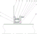
Fig. 1 is a schematic cross-sectional view of the pyrolysis rotary kiln floating seal arrangement of this patent.
Fig. 2 is an overall schematic view of the pyrolysis rotary kiln floating seal device of the present patent without the gland.
Fig. 3 is a partial perspective view of fig. 2.
FIG. 4 is a schematic view of a seal retainer of the pyrolysis rotary kiln floating seal arrangement of the present patent.
Fig. 5 is a schematic view of the gland of the pyrolysis rotary kiln floating seal device of this patent.
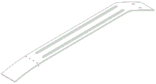
Fig. 6 is a schematic view of the spring steel sheet of the pyrolysis rotary kiln floating seal device of the patent.
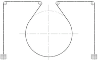
Fig. 7 is a schematic view showing the installation of the tension device of the pyrolysis rotary kiln floating sealing device of the patent on the upper part of the rotary kiln cylinder.
Fig. 8 is a schematic view showing the installation of the tension device of the pyrolysis rotary kiln floating sealing device of the patent on the lower part of the rotary kiln cylinder.
In the figure: 1-sealing seat ring, 11-inner ring, 12-outer ring, 13-neck ring, 2-gland, 3-spiral spring system, 31-connecting bolt, 32-spring, 33-spring pressure plate, 34-connecting nut, 4-packing, 5-spring steel sheet, 6-steel wire rope, 7-fixed pulley block, 8-counterweight block, 9-fixed cover shell and 10-rotary kiln cylinder.
Detailed Description
The invention is further explained below with reference to the drawings and examples, without thereby limiting the scope of protection of the invention, which is disclosed with the aim of protecting all technical modifications within the scope of the invention.
With reference to fig. 1-8, a pyrolysis rotary kiln floating seal device is arranged on the outer edge of a rotary kiln cylinder 10 at the joint of the rotary kiln cylinder 10 and a fixed cover shell 9; the device comprises a sealing seat ring 1, a gland 2, a spiral spring system 3, a packing 4, a plurality of spring steel sheets 5, a plurality of bolts, a plurality of screws, a plurality of nuts and a tensioning device.
The sealing ring 1 comprises an inner ring 11, an outer ring 12 and a collar 13 vertically arranged between the inner ring 11 and the outer ring 12; the inner ring 11 and the outer ring 12 are annular structures arranged in parallel, the outer diameters of the inner ring 11 and the outer ring 12 are the same, and the inner diameter of the outer ring 12 is larger than that of the inner ring 11; the inner diameter of the inner ring 11 is matched with the outer diameter of the rotary kiln cylinder 10; the diameter of the neck ring 13 is the same as the inner diameter of the outer ring 12, one end of the neck ring 13 is connected with the inner diameter of the outer ring 12, and the other end is arranged on the ring surface of the inner ring 11; the inner ring 11, the outer ring 12 and the neck ring 13 together form a sealing seat ring 1 with a double-ring surface structure and a circular groove in the middle; a fixing hole for installing the spring steel sheet 5 is arranged on the annular surface of the neck ring 13; holes connected with the fixed cover shell 9 are uniformly arranged on the ring surface of the inner ring 11; bolt mounting holes are uniformly formed in the ring surface of the outer ring 12; the sealing seat ring 1 is arranged on the outer edge of the rotary kiln barrel 10 through an inner ring 11; a plurality of bolts respectively pass through holes on the ring surface of the inner ring 11, and the sealing seat ring 1 is connected with the fixed cover shell 9 through nuts.
The gland 2 is of an annular structure with an annular boss in the middle, the outer diameter of the annular boss in the middle of the gland 2 is matched with the inner diameter of the outer ring 12 of the sealing seat ring 1, the gland 2 is arranged on the outer edge of the rotary kiln barrel 10, and the end part of the annular boss of the gland 2 is arranged in a circular groove of the sealing seat ring 1; through holes corresponding to the bolt mounting holes on the outer ring 12 of the sealing seat ring 1 are uniformly formed in the surface of the outer ring 12 of the gland 2; the spiral spring system 3 is respectively arranged in the corresponding bolt mounting hole and the through hole, and the circular groove of the sealing seat ring 1 and the end part of the annular boss of the gland 2 form an annular space on the outer edge of the rotary kiln cylinder body 10.
The spiral spring system 3 comprises a connecting bolt 31, a spring 32, a spring pressure plate 33 and a connecting nut 34; the connecting bolt 31 passes through a bolt mounting hole on the outer ring 12 of the seal retainer 1 and a through hole on the gland 2, the spring 32 is arranged on the connecting bolt 31, the spring pressing plate 33 is arranged on the outer side of the spring 32, and the connecting nut 34 is arranged on the outer side of the spring pressing plate 33 to connect the gland 2 with the seal retainer 1.
The packing 4 is a fiber braided packing with a rectangular cross section, the length of the packing 4 is matched with the outer diameter of the rotary kiln barrel 10, the packing 4 is arranged in an annular space formed by a circular groove of the sealing seat ring 1 on the outer edge of the rotary kiln barrel 10 and the gland 2 in an end-to-end manner, and four layers of packing 4 are arranged in a staggered manner according to the width interface of the annular space; two axial side edges of the packing 4 are respectively contacted with the annular surface of the inner ring 11 of the sealing seat ring 1 and the end surface of the annular boss of the gland 2; the spring steel sheets 5 are arranged on the outer ring of the packing 4 in a circumferential array, one end of each spring steel sheet 5 is provided with a screw hole connected with the packing 4, one end of each spring steel sheet 5 is fixed on the packing 4 through a plurality of screws, the other end of each spring steel sheet 5 is provided with a mounting hole corresponding to the fixing hole on the ring surface of the neck ring 13, a plurality of bolts penetrate through the corresponding fixing holes and the corresponding mounting holes, and the other end of each spring steel sheet 5 is fixed with the sealing seat ring 1 through nuts; two steel wire rope slotted holes are formed in the middle of the spring steel sheet 5 along the length direction of the spring steel sheet 5.
The tensioning device comprises a steel wire rope 6, a balancing weight 8 and a fixed pulley block 7, and comprises an upper group and a lower group; two steel wire ropes 6 of the upper group of tensioning devices respectively penetrate through steel wire rope slotted holes of the spring steel sheets 5 positioned on the circumference of 1/3 at the upper part of the packing 4; two steel wire ropes 6 of the lower group of tensioning devices respectively penetrate through steel wire rope slotted holes of the spring steel sheets 5 positioned on the circumference of 3/4 at the lower part of the packing 4; the neck ring 13 is provided with a through hole for the steel wire rope 6 to pass through the corresponding steel wire rope slot hole of the spring steel sheet 5 and then penetrate out of the neck ring 13; two ends of two steel wire ropes 6 of the upper group of tensioning devices penetrate through the through holes and then respectively obliquely bypass two groups of fixed pulley blocks 7 arranged below the side of the sealing ring seat towards two outer sides of the sealing ring seat; two ends of two steel wire ropes 6 of the lower group of tensioning devices penetrate through the through holes and then respectively obliquely bypass two groups of fixed pulley blocks 7 arranged above the sealing seat ring 1 towards the inner side of the upper part of the sealing seat ring 1; the counter weight blocks 8 are respectively arranged at two end parts of the steel wire rope 6, and the weight of the counter weight block 8 of the lower group of tensioning devices is larger than that of the counter weight block 8 of the upper group of tensioning devices; used for bearing the self weight of the packing 4.
In the working process, the sealing seat ring 1 is arranged on the outer edge of the rotary kiln cylinder 10 through the inner diameter of the inner ring 11 of the sealing seat ring 1, and the sealing seat ring 11 and the fixed cover shell 9 are fixed through bolts; selecting packing 4 with proper length and layer number according to the size of the outer edge of the pyrolysis rotary kiln cylinder 10 and arranging the packing on the outer edge of the pyrolysis rotary kiln cylinder 10; one side of the packing 4 is attached to the annular surface of the inner ring 11 of the sealing seat ring 1; the end face of an annular boss of the gland 2 is arranged in a circular groove of the sealing seat ring 1 and is attached to the other side of the packing 4; but gland 2 axial displacement compresses tightly 4 sides of packing, and gland 2 is connected by coil spring system 3 with seal retainer 1, gives the certain pretightning force of spring 32 through swivelling joint nut 34, and spring 32 compresses tightly gland 2, and gland 2 compresses tightly packing 4, adjusts the pressure of gland 2 to 4 sides of packing through the pretightning force of adjustment spring 32, and then guarantees 4 both sides of packing not to leak.
5 one end of spring steel sheet is passed through the fix with screw and is followed the dish and compress tightly packing 4 and not rotatory along with rotary kiln barrel 10, the other end is with bolt, nut and seal ring 1 fixed connection, when the part of packing 4 is beated along with rotary kiln barrel 10 radial runout, the local jack-up of packing 4 can be compensated to spring steel sheet 5's flexible deformation to give 4 radial pressure's of packing power all the time, make packing 4 in time kick-back in order to guarantee and do not have the gap that can leak between the rotary kiln barrel 10.
Because the diameter of the rotary kiln cylinder 10 is large, the weight of the packing 4 cannot be ignored, the packing 4 at the top of the rotary kiln cylinder 10 naturally compresses the cylinder due to the self gravity, and the packing 4 at the bottom of the rotary kiln cylinder 10 needs a radial pressing force overcoming the gravity of the packing 4 and upwards compresses the packing 4 on the rotary kiln cylinder 10; a steel wire rope 6 of the tensioning device penetrates through a steel wire rope slotted hole in the spring steel sheet 5 to be pressed on the outer circular surface of the spring steel sheet 5, and then the packing 4 is pressed on the outer edge of the rotary kiln cylinder 10. The packing 4 is adjusted by adjusting the weight of the balancing weight 8 to compress the outer edge of the rotary kiln barrel 10 appropriately in real time, so that the leakage between the packing 4 and the outer edge of the rotary kiln barrel 10 is avoided.
Claims (6)
1. The utility model provides a pyrolysis rotary kiln sealing device that floats, sets up on the rotary kiln barrel outer fringe that department was met to rotary kiln barrel and fixed cover casing, its characterized in that: the device comprises a sealing seat ring, a gland, a spiral spring system, a packing, a plurality of spring steel sheets, a plurality of bolts, a plurality of screws, a plurality of nuts and a tensioning device;
the sealing seat ring comprises an inner ring, an outer ring and a neck ring vertically arranged between the inner ring and the outer ring; the inner ring and the outer ring are of annular structures arranged in parallel, the outer diameters of the inner ring and the outer ring are the same, and the inner diameter of the outer ring is larger than that of the inner ring; the inner diameter of the inner ring is matched with the outer diameter of the rotary kiln cylinder; the diameter of the neck ring is the same as the inner diameter of the outer ring, one end of the neck ring is connected with the inner diameter of the outer ring, and the other end of the neck ring is arranged on the ring surface of the inner ring; the inner ring, the outer ring and the neck ring form a sealing seat ring with a double-ring surface structure with a circular groove in the middle; a fixed hole for installing the spring steel sheet is arranged on the ring surface of the neck ring; holes connected with the fixed cover shell are uniformly arranged on the ring surface of the inner ring; bolt mounting holes are uniformly formed in the ring surface of the outer ring; the sealing seat ring is arranged on the outer edge of the rotary kiln cylinder through an inner ring; a plurality of bolts respectively penetrate through holes on the ring surface of the inner ring, and the sealing seat ring is connected with the fixed cover shell through nuts;
the gland is of an annular structure with an annular boss in the middle, the outer diameter of the annular boss in the middle of the gland is matched with the inner diameter of the outer ring of the sealing seat ring, the gland is arranged on the outer edge of the rotary kiln barrel, and the end part of the annular boss of the gland is arranged in a circular groove of the sealing seat ring; through holes corresponding to the bolt mounting holes on the outer ring of the sealing seat ring are uniformly formed in the outer ring surface of the gland; the spiral spring systems are respectively arranged in the corresponding bolt mounting holes and the through holes, and the circular groove of the sealing seat ring and the end part of the annular boss of the gland form an annular space on the outer edge of the rotary kiln cylinder;
the spiral spring system comprises a connecting bolt, a spring pressing plate and a connecting nut; the connecting bolt penetrates through a bolt mounting hole in the outer ring of the sealing seat ring and a through hole in the gland, the spring is arranged on the connecting bolt, the spring pressing plate is arranged on the outer side of the spring, and the connecting nut is arranged on the outer side of the spring pressing plate and connects the gland with the sealing seat ring;
the packing is arranged on the outer edge of the rotary kiln barrel and is positioned in an annular space formed by the circular groove of the sealing seat ring and the gland, and two axial side edges of the packing are respectively in contact with the inner ring surface of the sealing seat ring and the end surface of the annular boss of the gland; the spring steel sheets are arranged on the outer ring of the packing in a circumferential array, one end of each spring steel sheet is provided with a screw hole connected with the packing, one end of each spring steel sheet is fixed on the packing through a plurality of screws, the other end of each spring steel sheet is provided with a mounting hole corresponding to the fixing hole in the ring surface of the neck ring, a plurality of bolts penetrate through the corresponding fixing holes and the corresponding mounting holes, and the other end of each spring steel sheet is fixed with the sealing seat ring through nuts; a steel wire rope slotted hole is formed in the middle of the spring steel sheet along the length direction of the spring steel sheet;
the tensioning device comprises a steel wire rope, a balancing weight and a fixed pulley block, and comprises an upper group and a lower group; the steel wire rope of the upper group of tensioning devices penetrates through a steel wire rope slotted hole of a spring steel sheet positioned on the circumference of the upper part 1/3-1/2 of the packing; the steel wire rope of the lower group of tensioning devices penetrates through a steel wire rope slotted hole of a spring steel sheet positioned on the circumference of the lower part 2/3-3/4 of the packing; the seal ring seat neck ring is provided with a through hole which is used for the steel wire rope to pass through the corresponding steel wire rope slot hole of the spring steel sheet and then penetrate out of the neck ring; two ends of a steel wire rope of the upper group of tensioning devices penetrate through the through holes and then respectively obliquely bypass two groups of fixed pulley blocks arranged below the side of the sealing ring seat towards two outer sides of the sealing ring seat; two ends of the steel wire rope of the lower group of tensioning devices penetrate through the through holes and then respectively obliquely bypass two groups of fixed pulley blocks arranged above the sealing seat ring towards the inner side of the upper part of the sealing seat ring; the balancing weights are respectively arranged at two ends of the steel wire rope.
2. The rotary pyrolysis kiln floating seal device according to claim 1, wherein: the packing is a fiber woven packing with a rectangular cross section, the length of the packing is matched with the outer diameter of the rotary kiln barrel, and the packing is arranged on the outer wall of the rotary kiln barrel in an end-to-end manner.
3. The rotary pyrolysis kiln floating seal device according to claim 2, wherein: the packing sets up 2-5 layers according to the annular space width, the setting is staggered at the kneck.
4. The rotary pyrolysis kiln floating seal device according to claim 1, wherein: two steel wire rope slotted holes are formed in the middle of the spring steel sheet.
5. The rotary pyrolysis kiln floating sealing pen as recited in claim 4, wherein: the number of the steel wire ropes of the tensioning device is consistent with the number of the steel wire rope slotted holes in the middle of the spring steel sheet.
6. The rotary pyrolysis kiln floating sealing pen as claimed in claim 1, wherein: the weight of the balancing weight of the lower group of tensioning devices is greater than that of the balancing weight of the upper group of tensioning devices.
Priority Applications (1)
| Application Number | Priority Date | Filing Date | Title |
|---|---|---|---|
| CN202010184697.8A CN111457719B (en) | 2020-03-17 | 2020-03-17 | Pyrolysis rotary kiln sealing device that floats |
Applications Claiming Priority (1)
| Application Number | Priority Date | Filing Date | Title |
|---|---|---|---|
| CN202010184697.8A CN111457719B (en) | 2020-03-17 | 2020-03-17 | Pyrolysis rotary kiln sealing device that floats |
Publications (2)
| Publication Number | Publication Date |
|---|---|
| CN111457719A CN111457719A (en) | 2020-07-28 |
| CN111457719B true CN111457719B (en) | 2022-03-22 |
Family
ID=71683175
Family Applications (1)
| Application Number | Title | Priority Date | Filing Date |
|---|---|---|---|
| CN202010184697.8A Active CN111457719B (en) | 2020-03-17 | 2020-03-17 | Pyrolysis rotary kiln sealing device that floats |
Country Status (1)
| Country | Link |
|---|---|
| CN (1) | CN111457719B (en) |
Families Citing this family (5)
| Publication number | Priority date | Publication date | Assignee | Title |
|---|---|---|---|---|
| CN114485149B (en) * | 2022-01-28 | 2024-02-09 | 广东中鹏新能科技有限公司 | Lithium battery material sintering rotary kiln with multiple sealing structures |
| CN119146725A (en) * | 2022-03-28 | 2024-12-17 | 青岛德固特节能装备股份有限公司 | Double-sealing combination of rotary kiln |
| CN114754144A (en) * | 2022-04-12 | 2022-07-15 | 青岛德固特节能装备股份有限公司 | Sealing device of DS I type rotary hub dryer |
| DE102022109305B4 (en) * | 2022-04-14 | 2024-04-25 | Eagleburgmann Germany Gmbh & Co. Kg | Sealing arrangement of a rotary kiln |
| CN115325818A (en) * | 2022-08-02 | 2022-11-11 | 荆门市格林美新材料有限公司 | Rotary kiln sealing device and rotary kiln and dust treatment system with the same |
Citations (4)
| Publication number | Priority date | Publication date | Assignee | Title |
|---|---|---|---|---|
| JP2001116460A (en) * | 1999-10-18 | 2001-04-27 | Toshiba Corp | Rotary furnace sealing device |
| CN103867724A (en) * | 2014-04-01 | 2014-06-18 | 大连容大资源循环利用咨询设计有限公司 | Multipoint compression high-temperature-resistant dynamic sealing device |
| CN105115293A (en) * | 2015-08-31 | 2015-12-02 | 中信重工机械股份有限公司 | Rotary kiln sealing device high in air-tightness |
| CN106090232B (en) * | 2016-07-29 | 2018-05-11 | 湖南万容科技股份有限公司 | A kind of rotary kiln inner cylinder rotary seal |
-
2020
- 2020-03-17 CN CN202010184697.8A patent/CN111457719B/en active Active
Patent Citations (4)
| Publication number | Priority date | Publication date | Assignee | Title |
|---|---|---|---|---|
| JP2001116460A (en) * | 1999-10-18 | 2001-04-27 | Toshiba Corp | Rotary furnace sealing device |
| CN103867724A (en) * | 2014-04-01 | 2014-06-18 | 大连容大资源循环利用咨询设计有限公司 | Multipoint compression high-temperature-resistant dynamic sealing device |
| CN105115293A (en) * | 2015-08-31 | 2015-12-02 | 中信重工机械股份有限公司 | Rotary kiln sealing device high in air-tightness |
| CN106090232B (en) * | 2016-07-29 | 2018-05-11 | 湖南万容科技股份有限公司 | A kind of rotary kiln inner cylinder rotary seal |
Also Published As
| Publication number | Publication date |
|---|---|
| CN111457719A (en) | 2020-07-28 |
Similar Documents
| Publication | Publication Date | Title |
|---|---|---|
| CN111457719A (en) | Pyrolysis rotary kiln sealing device that floats | |
| CN103867724B (en) | A kind of multiple spot compresses high temperature resistant dynamic seal apparatus | |
| CN103851289B (en) | Large high-temperature chicksan | |
| CN203926761U (en) | A kind of for lining plate of coal grinder bolt seal assembly | |
| CN202203413U (en) | Sealing device for biomass pyrolysis rotary furnace | |
| CN105650280A (en) | Rotary kiln sealing device and processing system with same | |
| CN206608545U (en) | One kind can limit pretightning force and easy-disassembling-assembling packing seal structure | |
| CN203926762U (en) | A kind of lining plate of coal grinder bolt seal assembly | |
| CN103438217B (en) | A kind of Universal rotary dynamic sealing device and apparatus for rotating | |
| CN201300077Y (en) | Grinding mill maintenance-free grinding roller assembly device | |
| CN213512076U (en) | Shaft end sealing and isolating device of gas pressurizer and gas pressurizer | |
| CN208669396U (en) | A kind of gas engine exhaust system explosion-proof decompression device | |
| CN202597885U (en) | Self-sealing device of high-temperature and high-pressure valve | |
| CN208982657U (en) | The stuffing seal component of pusher | |
| CN102022539A (en) | Inverse pressing shaft rod sealing structure | |
| CN201535609U (en) | Sealing Structure of Pulverized Coal Steam Rotary Cylinder Dryer | |
| CN209815173U (en) | Novel feeder | |
| CN221401623U (en) | Axial sealing device and distillation device | |
| CN220851165U (en) | Efficient axial sealing device | |
| CN201434080Y (en) | Container circumferential synchronous displacement sealing structure | |
| CN212080155U (en) | Corrosion-resistant and dry-grinding-resistant mechanical sealing element | |
| CN202327493U (en) | Explosion-proof high pressure resistant self-sealing rotating compensator | |
| CN101994835B (en) | Assembly annular synchronous displacement sealing structure | |
| CN224093830U (en) | Ball mill feeding end face sealing device | |
| CN106838329A (en) | Polyvinyl chloride mass polymerization bottom portion's mechanical seal assembly |
Legal Events
| Date | Code | Title | Description |
|---|---|---|---|
| PB01 | Publication | ||
| PB01 | Publication | ||
| SE01 | Entry into force of request for substantive examination | ||
| SE01 | Entry into force of request for substantive examination | ||
| GR01 | Patent grant | ||
| GR01 | Patent grant |