CN111453181A - Water bottle conversion bottle cap - Google Patents
Water bottle conversion bottle cap Download PDFInfo
- Publication number
- CN111453181A CN111453181A CN202010411755.6A CN202010411755A CN111453181A CN 111453181 A CN111453181 A CN 111453181A CN 202010411755 A CN202010411755 A CN 202010411755A CN 111453181 A CN111453181 A CN 111453181A
- Authority
- CN
- China
- Prior art keywords
- cap
- conversion
- bottle
- water
- valve core
- Prior art date
- Legal status (The legal status is an assumption and is not a legal conclusion. Google has not performed a legal analysis and makes no representation as to the accuracy of the status listed.)
- Pending
Links
- XLYOFNOQVPJJNP-UHFFFAOYSA-N water Substances O XLYOFNOQVPJJNP-UHFFFAOYSA-N 0.000 title claims abstract description 65
- 238000006243 chemical reaction Methods 0.000 title claims description 42
- 238000007789 sealing Methods 0.000 claims abstract description 18
- 230000006835 compression Effects 0.000 claims abstract description 11
- 238000007906 compression Methods 0.000 claims abstract description 11
- 241000405070 Percophidae Species 0.000 claims description 12
- 235000012206 bottled water Nutrition 0.000 claims description 10
- 230000029058 respiratory gaseous exchange Effects 0.000 claims 8
- VYPSYNLAJGMNEJ-UHFFFAOYSA-N Silicium dioxide Chemical compound O=[Si]=O VYPSYNLAJGMNEJ-UHFFFAOYSA-N 0.000 claims 4
- 239000000741 silica gel Substances 0.000 claims 4
- 229910002027 silica gel Inorganic materials 0.000 claims 4
- 239000002699 waste material Substances 0.000 abstract description 2
- 229920001296 polysiloxane Polymers 0.000 description 7
- 238000000034 method Methods 0.000 description 3
- 230000009286 beneficial effect Effects 0.000 description 1
- 230000002950 deficient Effects 0.000 description 1
- 238000010586 diagram Methods 0.000 description 1
- 230000035622 drinking Effects 0.000 description 1
- 230000000694 effects Effects 0.000 description 1
- 238000010438 heat treatment Methods 0.000 description 1
- 238000009434 installation Methods 0.000 description 1
Images


Classifications
-
- B—PERFORMING OPERATIONS; TRANSPORTING
- B65—CONVEYING; PACKING; STORING; HANDLING THIN OR FILAMENTARY MATERIAL
- B65D—CONTAINERS FOR STORAGE OR TRANSPORT OF ARTICLES OR MATERIALS, e.g. BAGS, BARRELS, BOTTLES, BOXES, CANS, CARTONS, CRATES, DRUMS, JARS, TANKS, HOPPERS, FORWARDING CONTAINERS; ACCESSORIES, CLOSURES, OR FITTINGS THEREFOR; PACKAGING ELEMENTS; PACKAGES
- B65D51/00—Closures not otherwise provided for
- B65D51/16—Closures not otherwise provided for with means for venting air or gas
- B65D51/1633—Closures not otherwise provided for with means for venting air or gas whereby venting occurs by automatic opening of the closure, container or other element
- B65D51/1644—Closures not otherwise provided for with means for venting air or gas whereby venting occurs by automatic opening of the closure, container or other element the element being a valve
-
- B—PERFORMING OPERATIONS; TRANSPORTING
- B65—CONVEYING; PACKING; STORING; HANDLING THIN OR FILAMENTARY MATERIAL
- B65D—CONTAINERS FOR STORAGE OR TRANSPORT OF ARTICLES OR MATERIALS, e.g. BAGS, BARRELS, BOTTLES, BOXES, CANS, CARTONS, CRATES, DRUMS, JARS, TANKS, HOPPERS, FORWARDING CONTAINERS; ACCESSORIES, CLOSURES, OR FITTINGS THEREFOR; PACKAGING ELEMENTS; PACKAGES
- B65D47/00—Closures with filling and discharging, or with discharging, devices
- B65D47/04—Closures with discharging devices other than pumps
- B65D47/06—Closures with discharging devices other than pumps with pouring spouts or tubes; with discharge nozzles or passages
-
- B—PERFORMING OPERATIONS; TRANSPORTING
- B65—CONVEYING; PACKING; STORING; HANDLING THIN OR FILAMENTARY MATERIAL
- B65D—CONTAINERS FOR STORAGE OR TRANSPORT OF ARTICLES OR MATERIALS, e.g. BAGS, BARRELS, BOTTLES, BOXES, CANS, CARTONS, CRATES, DRUMS, JARS, TANKS, HOPPERS, FORWARDING CONTAINERS; ACCESSORIES, CLOSURES, OR FITTINGS THEREFOR; PACKAGING ELEMENTS; PACKAGES
- B65D2547/00—Closures with filling and discharging, or with discharging, devices
- B65D2547/04—Closures with discharging devices other than pumps
- B65D2547/06—Closures with discharging devices other than pumps with pouring spouts ot tubes; with discharge nozzles or passages
- B65D2547/063—Details of spouts
- B65D2547/066—Details of spouts inserted in or attached to the base element
Landscapes
- Engineering & Computer Science (AREA)
- Mechanical Engineering (AREA)
- Closures For Containers (AREA)
Abstract
本发明公开了一种水瓶转换瓶盖,包括转换瓶盖本体、螺纹盖、阀芯和吸气盖,螺纹盖设置于转换瓶盖本体的底部,转换瓶盖本体的内部为水流通道,水流通道与螺纹盖内腔连通,阀芯底部设置有一环形卡接槽,阀芯顶部设置有一环形卡接台,环形卡接槽内安装有一密封垫,水流通道的底部进水口处设置有一卡接环,卡接环的直径大于阀芯的直径,卡接环的底部端面上设置有一圈凸筋,阀芯安装有密封垫的一端伸入到卡接环的底部,且密封垫的顶端面与凸筋相抵,阀芯位于水流通道的一端套设有压缩弹簧,压缩弹簧底端与卡接环的顶部端面连接,顶端与卡接台的底端面连接;本发明在水瓶连接加热器时,水不会从出水口流出,减少水资源浪费。
The invention discloses a water bottle converting cap, which comprises a converting cap body, a threaded cap, a valve core and a suction cap. The threaded cap is arranged at the bottom of the converting cap body, and the interior of the converting cap body is a water flow channel. It communicates with the inner cavity of the threaded cap, the bottom of the valve core is provided with an annular clamping groove, the top of the valve core is provided with an annular clamping platform, a sealing gasket is installed in the annular clamping groove, and a clamping ring is arranged at the bottom water inlet of the water flow channel. The diameter of the snap ring is larger than the diameter of the valve core, the bottom end face of the snap ring is provided with a ring of convex ribs, the end of the valve core with the gasket installed extends into the bottom of the snap ring, and the top surface of the gasket is connected to the convex ribs. On the contrary, one end of the valve core located in the water flow channel is sleeved with a compression spring, the bottom end of the compression spring is connected with the top end face of the clamping ring, and the top end is connected with the bottom end face of the clamping table; in the present invention, when the water bottle is connected to the heater, the water will not Flow out from the water outlet, reducing water waste.
Description
技术领域technical field
本发明涉及瓶装水瓶技术领域,特别是涉及一种水瓶转换瓶盖。The invention relates to the technical field of bottled water bottles, in particular to a water bottle changing cap.
背景技术Background technique
目前,现有在市面上流行的瓶装水转换瓶盖在使用中有不方便使用和漏水出来的缺点,在未装入加热器时,如手持瓶装水用力稍大,水会从出水口直接飙射出来,造成一定的损失。At present, the existing bottled water conversion caps that are popular on the market have the disadvantages of inconvenience and water leakage. When the heater is not installed, if you hold the bottled water with a little force, the water will directly surge from the water outlet. Shoot out, causing some damage.
发明内容SUMMARY OF THE INVENTION
本发明的目的是提供一种水瓶转换瓶盖,以解决上述现有技术存在的问题,在水瓶连接加热器时,水不会从出水口流出,减少水资源浪费。The purpose of the present invention is to provide a water bottle conversion cap to solve the above-mentioned problems in the prior art. When the water bottle is connected to the heater, the water will not flow out from the water outlet, thereby reducing the waste of water resources.
为实现上述目的,本发明提供了如下方案:For achieving the above object, the present invention provides the following scheme:
本发明提供一种水瓶转换瓶盖,包括包括转换瓶盖本体、螺纹盖、阀芯和吸气盖,所述螺纹盖设置于所述转换瓶盖本体的底部,用于与瓶装水瓶连接,所述转换瓶盖本体的内部还设置有竖向的水流通道,所述水流通道与所述螺纹盖内腔连通,所述阀芯底部设置有一环形卡接槽,所述阀芯顶部设置有一环形卡接台,所述环形卡接槽内安装有一密封垫,所述水流通道的底部进水口处设置有一卡接环,所述卡接环的直径大于所述阀芯的直径,所述卡接环的底部端面上设置有一圈凸筋,所述阀芯安装有所述密封垫的一端伸入到所述卡接环的底部,且所述密封垫的顶端面与所述所述凸筋相抵,所述阀芯位于所述水流通道的一端套设有压缩弹簧,所述压缩弹簧底端与所述卡接环的顶部端面连接,顶端与所述卡接台的底端面连接;所述吸气盖设置于所述转换瓶盖本体的顶部一侧,用于通过所述转换瓶盖本体向瓶装水瓶内通入空气。The invention provides a water bottle conversion cap, which includes a conversion cap body, a screw cap, a valve core and a suction cap. The screw cap is arranged at the bottom of the conversion cap body and is used for connecting with a bottled water bottle. The interior of the conversion bottle cap body is also provided with a vertical water flow channel, the water flow channel is communicated with the inner cavity of the threaded cap, the bottom of the valve core is provided with an annular clamping groove, and the top of the valve core is provided with an annular clamping groove A sealing pad is installed in the annular snap groove, a snap ring is arranged at the bottom water inlet of the water flow channel, the diameter of the snap ring is larger than the diameter of the valve core, and the snap ring A ring of raised ribs is arranged on the bottom end surface of the valve core, the end of the valve core with the sealing gasket protrudes into the bottom of the snap ring, and the top surface of the sealing gasket is in contact with the raised ribs, One end of the valve core located in the water flow channel is sleeved with a compression spring, the bottom end of the compression spring is connected with the top end face of the clamping ring, and the top end is connected with the bottom end face of the clamping table; the suction The cover is arranged on the top side of the conversion bottle cap body, and is used for introducing air into the bottled water bottle through the conversion bottle cap body.
优选地,所述螺纹盖与所述转换瓶盖本体一体成型,所述螺纹盖内设置有内螺纹。Preferably, the screw cap is integrally formed with the conversion bottle cap body, and an internal thread is provided in the screw cap.
优选地,所述转换瓶盖本体内还设置有一圈封水筋,所述封水筋伸入到所述螺纹盖的内腔内。Preferably, the conversion bottle cap body is further provided with a ring of water-sealing rib, and the water-sealing rib extends into the inner cavity of the threaded cap.
优选地,所述转换瓶盖本体的顶部一侧设置有吸气盖连接部,所述吸气盖与所述吸气盖连接部连接,所述吸气盖的外端设置有进气口,所述进气口通过气体通道连通所述螺纹盖的内腔,所述吸气盖内设置有一硅胶鸭嘴单向阀,所述硅胶鸭嘴单向阀的进气口与所述吸气盖的进气口相对。Preferably, the top side of the conversion bottle cap body is provided with a suction cap connecting part, the suction cap is connected with the suction cap connecting part, and the outer end of the suction cap is provided with an air inlet, The air inlet is communicated with the inner cavity of the threaded cover through a gas channel, a silicone duckbill check valve is arranged in the suction cover, and the air inlet of the silicone duckbill check valve is connected to the suction cover. The air intake is opposite.
优选地,所述吸气盖连接部的外壁上设置有一圈卡槽,所述吸气盖的内壁上设置有环形卡接部,所述卡接部卡入所述卡槽内。Preferably, an outer wall of the connecting portion of the suction cover is provided with a ring of clamping grooves, and an inner wall of the suction cover is provided with an annular clamping portion, and the clamping portion is clamped into the clamping groove.
优选地,所述硅胶鸭嘴单向阀进气端设置有台肩,所述台肩固定于吸气盖内端面于所述吸气盖连接部的外端面之间。Preferably, the inlet end of the silicone duckbill one-way valve is provided with a shoulder, and the shoulder is fixed between the inner end face of the suction cover and the outer end face of the connecting part of the suction cover.
优选地,所述吸气盖连接部与所述转换瓶盖本体一体成型。Preferably, the suction cap connecting portion is integrally formed with the conversion bottle cap body.
本发明相对于现有技术取得了以下有益技术效果:The present invention has achieved the following beneficial technical effects with respect to the prior art:
本发明提供的水瓶转换瓶盖,用于实际瓶装水可直接使用于加热器上进行加热饮用的装置,在使用时由于设置有阀芯,倒置安装水不会从出水口流出,解决了目前市面上结构功能较单一和有部分缺陷的连接器的难题。The water bottle conversion cap provided by the present invention is used for a device in which the actual bottled water can be directly used on a heater for heating and drinking. During use, due to the valve core, the inverted installation water will not flow out from the water outlet, which solves the problem in the current market. The problem is that the structure and function of the connector are relatively single and partially defective.
附图说明Description of drawings
为了更清楚地说明本发明实施例或现有技术中的技术方案,下面将对实施例中所需要使用的附图作简单地介绍,显而易见地,下面描述中的附图仅仅是本发明的一些实施例,对于本领域普通技术人员来讲,在不付出创造性劳动的前提下,还可以根据这些附图获得其他的附图。In order to more clearly illustrate the embodiments of the present invention or the technical solutions in the prior art, the accompanying drawings required in the embodiments will be briefly introduced below. Obviously, the drawings in the following description are only some of the present invention. In the embodiments, for those of ordinary skill in the art, other drawings can also be obtained according to these drawings without any creative effort.
图1为本发明中水瓶转换瓶盖的立体结构示意图;Fig. 1 is the three-dimensional structure schematic diagram of the water bottle conversion cap in the present invention;
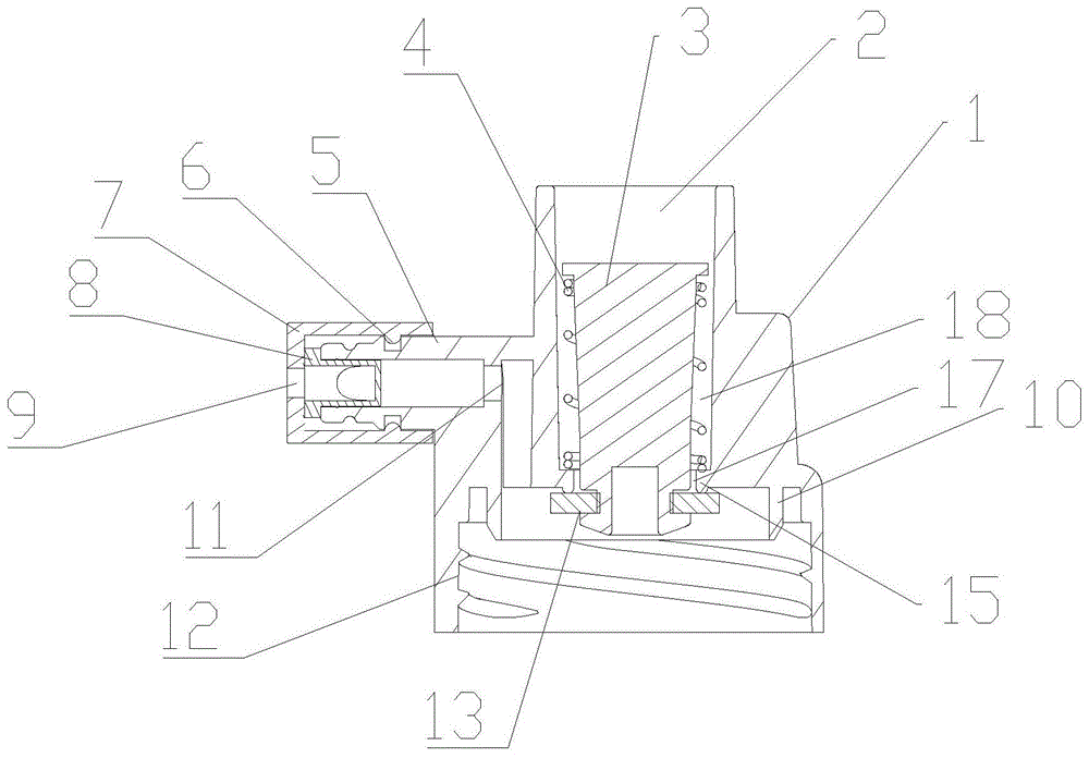
图2为本发明中水瓶转换瓶盖的剖面图;Fig. 2 is the sectional view of the water bottle conversion cap in the present invention;
图3为本发明中转换瓶盖本体的剖面图;Fig. 3 is the sectional view of converting the bottle cap body in the present invention;
图中:1-转换瓶盖本体、2-出水口、3-阀芯、4-压缩弹簧、5-吸气盖连接部、6-卡接部、7-吸气盖、8-硅胶鸭嘴单向阀、9-进气孔、10-封水筋、11-气体通道、12-螺纹盖、13-密封垫、14-环形卡接槽、15-卡接环、16-凸筋、17-进水口、18-水流通道。In the picture: 1- Conversion bottle cap body, 2- Water outlet, 3- Valve core, 4- Compression spring, 5- Suction cap connecting part, 6- Clamping part, 7- Suction cap, 8- Silicone duckbill One-way valve, 9-air inlet, 10-sealing water rib, 11-gas channel, 12-thread cover, 13-seal gasket, 14-ring snap groove, 15- snap ring, 16-rib, 17 -Water inlet, 18-water flow channel.
具体实施方式Detailed ways
下面将结合本发明实施例中的附图,对本发明实施例中的技术方案进行清楚、完整地描述,显然,所描述的实施例仅仅是本发明一部分实施例,而不是全部的实施例。基于本发明中的实施例,本领域普通技术人员在没有做出创造性劳动前提下所获得的所有其他实施例,都属于本发明保护的范围。The technical solutions in the embodiments of the present invention will be clearly and completely described below with reference to the accompanying drawings in the embodiments of the present invention. Obviously, the described embodiments are only a part of the embodiments of the present invention, but not all of the embodiments. Based on the embodiments of the present invention, all other embodiments obtained by those of ordinary skill in the art without creative efforts shall fall within the protection scope of the present invention.
本发明的目的是提供一种水瓶转换瓶盖,以解决现有技术存在的问题。The purpose of the present invention is to provide a water bottle changing cap to solve the problems existing in the prior art.
为使本发明的上述目的、特征和优点能够更加明显易懂,下面结合附图和具体实施方式对本发明作进一步详细的说明。In order to make the above objects, features and advantages of the present invention more clearly understood, the present invention will be described in further detail below with reference to the accompanying drawings and specific embodiments.
本实施例提供一种水瓶转换瓶盖,如图1-3所示,包括转换瓶盖本体1、螺纹盖12、阀芯3和吸气盖7,螺纹盖12用于与瓶装水瓶连接,螺纹盖12内设置有内螺纹并一体成型于转换瓶盖本体1的底部,转换瓶盖本体1的内部还设置有竖向的水流通道18,水流通道18与螺纹盖12内腔连通,水流通道18顶部为出水口2,底部为进水口17,阀芯3底部设置有一环形卡接槽14,阀芯3顶部设置有一环形卡接台,环形卡接槽14内安装有一密封垫13,水流通道18的底部进水口17处设置有一卡接环15,卡接环15的直径大于阀芯3的直径,使二者之间能够形成过水通道,卡接环15的底部端面上设置有一圈凸筋16,阀芯3安装有密封垫13的一端伸入到卡接环15的底部,且密封垫13的顶端面与凸筋16相抵,阀芯3位于水流通道18的一端套设有压缩弹簧4,压缩弹簧4底端与卡接环15的顶部端面连接,顶端与卡接台的底端面连接,压缩弹簧4的设置,使密封垫13压紧在凸筋16上实现密封,吸气盖7设置于转换瓶盖本体1的顶部一侧,用于通过转换瓶盖本体1向瓶装水瓶内通入空气。This embodiment provides a water bottle conversion cap, as shown in Figures 1-3, including a
于本具体实施例中,转换瓶盖本体1内还设置有一圈封水筋10,封水筋10伸入到螺纹盖12的内腔内,封水筋10一体成型于转换瓶盖本体1上,为一功能筋,将螺纹盖12与水瓶口连接时用于卡住水瓶口内侧,防止水从瓶口流出。In this specific embodiment, the conversion
于本具体实施例中,转换瓶盖本体1的顶部一侧一体设置有吸气盖连接部5,吸气盖连接部5的外壁上设置有一圈卡槽,吸气盖7的内壁上设置有环形卡接部6,卡接部6卡入卡槽内,实现吸气盖7与吸气盖连接部5的连接,吸气盖7的外端设置有进气口,进气口通过气体通道11连通螺纹盖12的内腔,吸气盖7内设置有一硅胶鸭嘴单向阀8,硅胶鸭嘴单向阀8的进气口与吸气盖7的进气口相对;具体地,硅胶鸭嘴单向阀8进气端设置有台肩,台肩固定于吸气盖7内端面于吸气盖连接部5的外端面之间。In this specific embodiment, the top side of the conversion
本发明中的水瓶转换瓶盖使用方法如下:将转换瓶盖本体1上螺纹盖12与水瓶连接后,插入加热器,加热器会顶开阀芯3,同步带动密封垫13脱离进水口17处的凸筋16,使水从瓶内经过进水口17,从出水口2流出进入加热器。当瓶内压力达到一定值时,硅胶鸭嘴单向阀8打开,空气从吸气盖7上的进气孔9通过转换瓶盖本体1开设的气体通道11进入瓶内达到平衡。The use method of the water bottle conversion cap in the present invention is as follows: after connecting the
本发明应用了具体个例对本发明的原理及实施方式进行了阐述,以上实施例的说明只是用于帮助理解本发明的方法及其核心思想;同时,对于本领域的一般技术人员,依据本发明的思想,在具体实施方式及应用范围上均会有改变之处。综上,本说明书内容不应理解为对本发明的限制。The present invention uses specific examples to illustrate the principles and implementations of the present invention, and the descriptions of the above embodiments are only used to help understand the method and the core idea of the present invention; There will be changes in the specific implementation and application scope. In conclusion, the contents of this specification should not be construed as limiting the present invention.
Claims (7)
Priority Applications (1)
| Application Number | Priority Date | Filing Date | Title |
|---|---|---|---|
| CN202010411755.6A CN111453181A (en) | 2020-05-15 | 2020-05-15 | Water bottle conversion bottle cap |
Applications Claiming Priority (1)
| Application Number | Priority Date | Filing Date | Title |
|---|---|---|---|
| CN202010411755.6A CN111453181A (en) | 2020-05-15 | 2020-05-15 | Water bottle conversion bottle cap |
Publications (1)
| Publication Number | Publication Date |
|---|---|
| CN111453181A true CN111453181A (en) | 2020-07-28 |
Family
ID=71674332
Family Applications (1)
| Application Number | Title | Priority Date | Filing Date |
|---|---|---|---|
| CN202010411755.6A Pending CN111453181A (en) | 2020-05-15 | 2020-05-15 | Water bottle conversion bottle cap |
Country Status (1)
| Country | Link |
|---|---|
| CN (1) | CN111453181A (en) |
Cited By (1)
| Publication number | Priority date | Publication date | Assignee | Title |
|---|---|---|---|---|
| CN112918903A (en) * | 2021-04-07 | 2021-06-08 | 刘红伟 | One-way valve bottle body sealing mode of automatic liquid discharging machine |
Citations (8)
| Publication number | Priority date | Publication date | Assignee | Title |
|---|---|---|---|---|
| WO2001037713A1 (en) * | 1999-11-23 | 2001-05-31 | Qing Li | A close and no pollution drinking water machine for bottled water |
| CN201610987U (en) * | 2010-01-09 | 2010-10-20 | 罗泳扬 | Device for fast connecting pipe |
| CN104257282A (en) * | 2014-09-30 | 2015-01-07 | 陈楚娇 | A water inlet device for an instant hot water dispenser |
| TWM549587U (en) * | 2017-04-06 | 2017-10-01 | Hawpin Electric Co Ltd | Negative hydrogen alkaline water dispenser for bottled water |
| CN108552955A (en) * | 2018-05-20 | 2018-09-21 | 王伟 | A kind of instant heating type drinking machine |
| CN209421731U (en) * | 2018-12-18 | 2019-09-24 | 陆璐 | Water receiving bottle cap for water dispenser |
| CN110301817A (en) * | 2019-07-16 | 2019-10-08 | 芜湖艾尔达科技有限责任公司 | A kind of water bottle connector |
| CN212448791U (en) * | 2020-05-15 | 2021-02-02 | 宁波家尚电器有限公司 | Water bottle conversion bottle cap |
-
2020
- 2020-05-15 CN CN202010411755.6A patent/CN111453181A/en active Pending
Patent Citations (8)
| Publication number | Priority date | Publication date | Assignee | Title |
|---|---|---|---|---|
| WO2001037713A1 (en) * | 1999-11-23 | 2001-05-31 | Qing Li | A close and no pollution drinking water machine for bottled water |
| CN201610987U (en) * | 2010-01-09 | 2010-10-20 | 罗泳扬 | Device for fast connecting pipe |
| CN104257282A (en) * | 2014-09-30 | 2015-01-07 | 陈楚娇 | A water inlet device for an instant hot water dispenser |
| TWM549587U (en) * | 2017-04-06 | 2017-10-01 | Hawpin Electric Co Ltd | Negative hydrogen alkaline water dispenser for bottled water |
| CN108552955A (en) * | 2018-05-20 | 2018-09-21 | 王伟 | A kind of instant heating type drinking machine |
| CN209421731U (en) * | 2018-12-18 | 2019-09-24 | 陆璐 | Water receiving bottle cap for water dispenser |
| CN110301817A (en) * | 2019-07-16 | 2019-10-08 | 芜湖艾尔达科技有限责任公司 | A kind of water bottle connector |
| CN212448791U (en) * | 2020-05-15 | 2021-02-02 | 宁波家尚电器有限公司 | Water bottle conversion bottle cap |
Cited By (1)
| Publication number | Priority date | Publication date | Assignee | Title |
|---|---|---|---|---|
| CN112918903A (en) * | 2021-04-07 | 2021-06-08 | 刘红伟 | One-way valve bottle body sealing mode of automatic liquid discharging machine |
Similar Documents
| Publication | Publication Date | Title |
|---|---|---|
| CN104523172B (en) | Liquid storage device and storage cover of dosing machine | |
| CN112110030A (en) | External spring pump distributor with safety outlet valve | |
| CN102069949B (en) | Liquid bottle cap opened by screwing cap | |
| WO2022052317A1 (en) | Food pump having external spring and safety outlet valve | |
| CN212448791U (en) | Water bottle conversion bottle cap | |
| CN205365228U (en) | Vehicle fuel tank cap | |
| CN206439449U (en) | Check-valves | |
| CN209956547U (en) | Special high strength packaging bottle of cosmetics | |
| CN203682139U (en) | Emulsion outlet spray head | |
| CN204624203U (en) | A lotion pump with a waterproof ring | |
| CN211582651U (en) | Water bottle connector | |
| CN202604618U (en) | Bottle stopper | |
| CN221311099U (en) | Pressure-resistant high-polymer perfume spray head based on double-sided sealing of piston | |
| CN216494868U (en) | Bottleneck fixed knot of bubble water machine constructs and bubble water machine | |
| CN213063784U (en) | Gas inlet adjusting assembly for gas engine | |
| CN204410649U (en) | A kind of proportioning machine liquid accumulator and storing lid | |
| CN206724396U (en) | Versatile humidifier | |
| CN205998375U (en) | A kind of bottle cap for balancing hydraulic giant air pressure | |
| CN201971275U (en) | A liquid bottle cap that can be opened by screw cap | |
| CN108910271B (en) | Flower core squeezing cover | |
| CN208264911U (en) | A kind of encapsulating structure of Drinking water bucketr | |
| CN204473459U (en) | A kind of coarse emulsion pump | |
| CN207111979U (en) | A kind of valve structure of leakproof | |
| CN221820697U (en) | Cap assembly and beverage container | |
| CN222085240U (en) | Structure and connector integrating one-way valve and quick-insert function |
Legal Events
| Date | Code | Title | Description |
|---|---|---|---|
| PB01 | Publication | ||
| PB01 | Publication | ||
| SE01 | Entry into force of request for substantive examination | ||
| SE01 | Entry into force of request for substantive examination | ||
| RJ01 | Rejection of invention patent application after publication | ||
| RJ01 | Rejection of invention patent application after publication |
Application publication date: 20200728 |