CN111442251A - An energy-saving lamp holder with a lamp tube that can be disassembled and lowered - Google Patents
An energy-saving lamp holder with a lamp tube that can be disassembled and lowered Download PDFInfo
- Publication number
- CN111442251A CN111442251A CN202010334268.4A CN202010334268A CN111442251A CN 111442251 A CN111442251 A CN 111442251A CN 202010334268 A CN202010334268 A CN 202010334268A CN 111442251 A CN111442251 A CN 111442251A
- Authority
- CN
- China
- Prior art keywords
- lamp holder
- energy
- sleeve
- spline
- lamp
- Prior art date
- Legal status (The legal status is an assumption and is not a legal conclusion. Google has not performed a legal analysis and makes no representation as to the accuracy of the status listed.)
- Granted
Links
Images


Classifications
-
- F—MECHANICAL ENGINEERING; LIGHTING; HEATING; WEAPONS; BLASTING
- F21—LIGHTING
- F21V—FUNCTIONAL FEATURES OR DETAILS OF LIGHTING DEVICES OR SYSTEMS THEREOF; STRUCTURAL COMBINATIONS OF LIGHTING DEVICES WITH OTHER ARTICLES, NOT OTHERWISE PROVIDED FOR
- F21V21/00—Supporting, suspending, or attaching arrangements for lighting devices; Hand grips
- F21V21/36—Hoisting or lowering devices, e.g. for maintenance
-
- F—MECHANICAL ENGINEERING; LIGHTING; HEATING; WEAPONS; BLASTING
- F21—LIGHTING
- F21V—FUNCTIONAL FEATURES OR DETAILS OF LIGHTING DEVICES OR SYSTEMS THEREOF; STRUCTURAL COMBINATIONS OF LIGHTING DEVICES WITH OTHER ARTICLES, NOT OTHERWISE PROVIDED FOR
- F21V19/00—Fastening of light sources or lamp holders
- F21V19/04—Fastening of light sources or lamp holders with provision for changing light source, e.g. turret
-
- F—MECHANICAL ENGINEERING; LIGHTING; HEATING; WEAPONS; BLASTING
- F21—LIGHTING
- F21V—FUNCTIONAL FEATURES OR DETAILS OF LIGHTING DEVICES OR SYSTEMS THEREOF; STRUCTURAL COMBINATIONS OF LIGHTING DEVICES WITH OTHER ARTICLES, NOT OTHERWISE PROVIDED FOR
- F21V21/00—Supporting, suspending, or attaching arrangements for lighting devices; Hand grips
- F21V21/02—Wall, ceiling, or floor bases; Fixing pendants or arms to the bases
- F21V21/03—Ceiling bases, e.g. ceiling roses
Landscapes
- Engineering & Computer Science (AREA)
- General Engineering & Computer Science (AREA)
- Non-Portable Lighting Devices Or Systems Thereof (AREA)
Abstract
Description
技术领域technical field
本发明涉及节能灯技术领域,具体地说是一种可将灯管拆卸并降下的节能灯座。The invention relates to the technical field of energy-saving lamps, in particular to an energy-saving lamp holder which can be disassembled and lowered.
背景技术Background technique
在建造一个房间时,为了使房间空间更大,且避免碰到人的脑袋,房间的天花板会比人高出很多,为了给房间提供更好的照明,通常在房间天花板上安装吊灯,同样的为了防止碰撞,吊灯也会设置在人碰不到的地方,但是电灯在使用时很容易出现损坏,那就需要经常更换灯管,要更换高处的灯管,就要人垫一个凳子或爬梯子爬到高处,会有摔倒受伤的危险,且人工更换灯管时直接接触的话还有可能发生触电的危险。When building a room, in order to make the room larger and avoid touching people's heads, the ceiling of the room will be much higher than people's heads. In order to provide better lighting for the room, chandeliers are usually installed on the ceiling of the room. The same In order to prevent collisions, chandeliers will also be placed in places where people can't touch them, but electric lights are prone to damage during use, so the lamps need to be replaced frequently. To replace the lamps in high places, people need to put a stool or climb a ladder. If the lamp climbs to a high place, there is a danger of falling and injury, and there is a danger of electric shock if it is directly touched when the lamp is replaced manually.
发明内容SUMMARY OF THE INVENTION
针对上述技术的不足,本发明提出了一种可将灯管拆卸并降下的节能灯座,能够克服上述缺陷。In view of the deficiencies of the above-mentioned technologies, the present invention provides an energy-saving lamp holder with a lamp tube that can be disassembled and lowered, which can overcome the above-mentioned deficiencies.
本发明的一种可将灯管拆卸并降下的节能灯座,包括灯座,所述灯座下面安装有灯罩,所述灯座中部设置有固定腔,所述固定腔中设置有固定机构,所述灯座下部设置有环形腔,所述环形腔中设置有夹具机构,所述固定机构包括转动安装于所述固定腔中的转动螺纹套,所述转动螺纹套上固定安装有传动齿轮,所述转动螺纹套中螺纹安装有节能灯尾,所述节能灯尾上安装有节能灯管,所述夹具机构包括上下滑动安装于所述环形腔中的环形安装块,所述环形安装块左右部中转动安装有以所述转动螺纹套为中心、中心对称的外螺纹花键套,所述环形腔上壁上固定安装有两个以所述转动螺纹套为中心、中心对称的内螺纹套,所述外螺纹花键套上端螺纹安装于所述内螺纹套中,所述外螺纹花键套上均安装有棘轮和推力齿轮,所述棘轮设置于定位块中,所述定位块安装于所述环形安装块上方,所述定位块中前后滑动安装有以所述转动螺纹套为中心、中心对称的棘齿滑块,所述棘齿滑块上设置有与所述定位块连接的压力弹簧,所述棘齿滑块中上下滑动安装有楔形限位块,所述楔形限位块固定安装于所述环形腔上壁上,所述楔形限位块能在所述环形安装块和所述定位块中上下滑动,两个所述推力齿轮分别以所述转动螺纹套为中心、中心对称的齿条滑块啮合连接,所述齿条滑块左右滑动安装于所述环形安装块中,所述齿条滑块靠近所述转动螺纹套一侧转动安装有转动轴,所述转动轴上固定安装有摆动齿轮和夹具安装板,所述摆动齿轮上侧啮合连接有两块齿条板,两块所述齿条板固定安装于所述环形安装块内侧,所述夹具安装板中左右滑动安装有支撑滑块,所述支撑滑块靠近所述转动螺纹套一侧设置有与所述夹具安装板连接的支撑弹簧,所述支撑滑块中转动安装有支撑杆,所述支撑杆上端转动安装于所述齿条滑块中,所述夹具安装板远离所述转动螺纹套一侧设置有抬板,所述抬板中上下滑动安装有缓冲夹板,所述缓冲夹板靠近所述转动螺纹套一侧固定安装有导杆,所述导杆上下滑动安装于所述夹具安装板中,所述导杆上设置有连接所述和所述夹具安装板的缓冲弹簧。An energy-saving lamp holder capable of disassembling and lowering a lamp tube of the present invention comprises a lamp holder, a lamp shade is installed under the lamp holder, a fixing cavity is arranged in the middle of the lamp holder, and a fixing mechanism is arranged in the fixing cavity, An annular cavity is arranged at the lower part of the lamp holder, a clamp mechanism is arranged in the annular cavity, the fixing mechanism comprises a rotating threaded sleeve rotatably installed in the fixing cavity, and a transmission gear is fixedly installed on the rotating threaded sleeve, An energy-saving lamp tail is threadedly installed in the rotating threaded sleeve, and an energy-saving lamp tube is installed on the energy-saving lamp tail. A centrally symmetric outer threaded spline sleeve is rotatably installed with the rotating threaded sleeve as the center, and two inner threaded sleeves centered on the rotating threaded sleeve are fixedly installed on the upper wall of the annular cavity, and the center is symmetrical. The upper end of the external thread spline sleeve is threadedly installed in the internal thread sleeve, a ratchet wheel and a thrust gear are installed on the external thread spline sleeve, the ratchet wheel is arranged in the positioning block, and the positioning block is installed in the Above the annular mounting block, the positioning block is slidably installed forward and backward with the rotating threaded sleeve as the center and a center-symmetric ratchet sliding block, and the ratchet sliding block is provided with a pressure spring connected with the positioning block. , a wedge-shaped limit block is slidably installed up and down in the ratchet slider, the wedge-shaped limit block is fixedly installed on the upper wall of the annular cavity, and the wedge-shaped limit block can be installed between the annular installation block and the The positioning block slides up and down, and the two thrust gears are respectively meshed and connected with the rotating threaded sleeve as the center and the center-symmetric rack sliders are installed in the annular mounting block by sliding left and right. A rotating shaft is rotatably installed on the side of the rack slider close to the rotating threaded sleeve, a swing gear and a fixture mounting plate are fixedly installed on the rotating shaft, and two rack plates are meshed and connected on the upper side of the swing gear. The rack plate is fixedly installed on the inner side of the annular installation block, and a support slider is installed in the clamp mounting plate to slide left and right, and the support slider is installed with the clamp on the side close to the rotating threaded sleeve. A support spring connected to a plate, a support rod is rotatably installed in the support slider, the upper end of the support rod is rotatably installed in the rack slider, and the clamp mounting plate is provided with a lift on the side away from the rotating threaded sleeve. A buffer splint is installed in the lift plate to slide up and down, a guide rod is fixedly installed on the side of the buffer splint close to the rotating threaded sleeve, and the guide rod is slid up and down and installed in the fixture mounting plate. The rod is provided with a buffer spring connecting the clamp mounting plate and the rod.
有益地,以下对所述固定机构进行详细说明,所述固定机构还包括设置于所述灯座中的电机,所述电机下侧连接有动力轴,所述动力轴转动安装于所述灯座中,所述动力轴下端固定安装有驱动齿轮,所述驱动齿轮后侧与所述传动齿轮啮合。Beneficially, the fixing mechanism will be described in detail below. The fixing mechanism further includes a motor arranged in the lamp holder, a power shaft is connected to the lower side of the motor, and the power shaft is rotatably mounted on the lamp holder. Among them, a drive gear is fixedly installed at the lower end of the power shaft, and the rear side of the drive gear meshes with the transmission gear.
有益地,以下对所述夹具机构进行详细说明,所述夹具机构还包括固定安装于所述动力轴上的驱动带轮,所述驱动带轮通过皮带连接有两个以所述转动螺纹套为中心、中心对称的传动带轮,所述传动带轮安装于花键轴上,所述花键轴转动安装于所述灯座中,所述花键轴下端花键安装于所述外螺纹花键套中,所述花键轴上端固定安装有驱动锥齿轮,所述驱动锥齿轮后侧啮合连接有传动锥齿轮,所述传动锥齿轮安装于牵引轴上,所述牵引轴转动安装于所述灯座中,所述牵引轴上固定安装有绕线筒,所述绕线筒上绕有细绳,所述细绳下端穿过所述花键轴中间的通孔连接于所述外螺纹花键套中。Beneficially, the clamp mechanism will be described in detail below. The clamp mechanism also includes a drive pulley fixedly mounted on the power shaft. The drive pulley is connected by a belt with two rotating threaded sleeves. Center, center-symmetric transmission pulley, the transmission pulley is installed on the spline shaft, the spline shaft is rotatably installed in the lamp holder, and the spline at the lower end of the spline shaft is installed on the external thread spline sleeve The upper end of the spline shaft is fixedly installed with a drive bevel gear, the rear side of the drive bevel gear is meshed with a drive bevel gear, the drive bevel gear is mounted on the traction shaft, and the traction shaft is rotatably mounted on the lamp In the seat, a bobbin is fixedly installed on the traction shaft, a thin rope is wound on the bobbin, and the lower end of the thin rope is connected to the external thread spline through the through hole in the middle of the spline shaft. set.
有益效果为:该设备设置于房间天花板上,在更换其中的灯管时,不需要人爬到高处亲手更换,其夹具能将灯管抓牢然后从灯座上拧下,并随夹具一起缓缓降下到人正常能够到的地方,手动更换为新的灯管后,能再升起将其安装到灯座上,同时该装置无需人工直接操作,有效避免了触电风险。The beneficial effects are as follows: the device is arranged on the ceiling of the room. When replacing the lamp tube, there is no need for people to climb to a high place to replace it by hand. Slowly lower it to a place where people can normally go. After manually replacing it with a new lamp, it can be raised again to install it on the lamp socket. At the same time, the device does not need manual operation, which effectively avoids the risk of electric shock.
附图说明Description of drawings
为了更清楚地说明发明实施例或现有技术中的技术方案,下面将对实施例或现有技术描述中所需要使用的附图作简单地介绍,显而易见地,下面描述中的附图仅仅是发明的一些实施例,对于本领域普通技术人员来讲,在不付出创造性劳动的前提下,还可以根据这些附图获得其他的附图。In order to illustrate the embodiments of the invention or the technical solutions in the prior art more clearly, the following briefly introduces the accompanying drawings that need to be used in the description of the embodiments or the prior art. Obviously, the drawings in the following description are only For some embodiments of the invention, for those of ordinary skill in the art, other drawings can also be obtained according to these drawings without any creative effort.
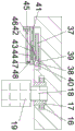
图1为本发明的一种可将灯管拆卸并降下的节能灯座结构示意图;1 is a schematic structural diagram of an energy-saving lamp holder with a lamp tube that can be disassembled and lowered according to the present invention;
图2为图1中“A-A”方向剖视结构示意图;Fig. 2 is a schematic view of the cross-sectional structure in the direction "A-A" in Fig. 1;
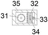
图3为图2中“B-B”方向剖视结构示意图;Fig. 3 is a schematic view of the cross-sectional structure in the direction "B-B" in Fig. 2;
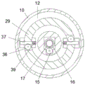
图4为图2中“C-C”方向剖视结构示意图;Fig. 4 is a schematic view of the cross-sectional structure along the "C-C" direction in Fig. 2;
图5为图1中“D-D”方向剖视结构示意图。FIG. 5 is a schematic diagram of a cross-sectional structure along the “D-D” direction in FIG. 1 .
具体实施方式Detailed ways
本说明书中公开的所有特征,或公开的所有方法或过程中的步骤,除了互相排斥的特征和/或步骤以外,均可以以任何方式组合。All features disclosed in this specification, or all disclosed steps in a method or process, may be combined in any way except mutually exclusive features and/or steps.
下面结合图1-5对本发明进行详细说明,为叙述方便,现对下文所说的方位规定如下:下文所说的上下左右前后方向与图1本身投影关系的上下左右前后方向一致。The present invention will be described in detail below in conjunction with Figures 1-5. For the convenience of description, the orientations mentioned below are now defined as follows: the up-down, left-right, front-rear directions mentioned below are consistent with the up-down, left-right, front-rear directions of the projection relationship of Figure 1 itself.
本发明装置的一种可将灯管拆卸并降下的节能灯座,包括灯座10,所述灯座10下面安装有灯罩49,所述灯座10中部设置有固定腔11,所述固定腔11中设置有能将节能灯固定到所述灯座10中的固定机构,所述灯座10下部设置有环形腔12,所述环形腔12中设置有能将节能灯夹住从而辅助安装且能运送节能灯的夹具机构,所述固定机构包括转动安装于所述固定腔11中的转动螺纹套17,所述转动螺纹套17上固定安装有传动齿轮16,所述转动螺纹套17中螺纹安装有节能灯尾18,所述节能灯尾18上安装有节能灯管19,所述夹具机构包括上下滑动安装于所述环形腔12中的环形安装块29,所述环形安装块29左右部中转动安装有以所述转动螺纹套17为中心、中心对称的外螺纹花键套28,所述环形腔12上壁上固定安装有两个以所述转动螺纹套17为中心、中心对称的内螺纹套30,所述外螺纹花键套28上端螺纹安装于所述内螺纹套30中,所述外螺纹花键套28上均安装有棘轮31和推力齿轮36,所述棘轮31设置于定位块35中,所述定位块35安装于所述环形安装块29上方,所述定位块35中前后滑动安装有以所述转动螺纹套17为中心、中心对称的棘齿滑块32,所述棘齿滑块32上设置有与所述定位块35连接的压力弹簧33,所述棘齿滑块32中上下滑动安装有楔形限位块34,所述楔形限位块34固定安装于所述环形腔12上壁上,所述楔形限位块34能在所述环形安装块29和所述定位块35中上下滑动,两个所述推力齿轮36分别以所述转动螺纹套17为中心、中心对称的齿条滑块37啮合连接,所述齿条滑块37左右滑动安装于所述环形安装块29中,所述齿条滑块37靠近所述转动螺纹套17一侧转动安装有转动轴38,所述转动轴38上固定安装有摆动齿轮39和夹具安装板41,所述摆动齿轮39上侧啮合连接有两块齿条板40,两块所述齿条板40固定安装于所述环形安装块29内侧,所述夹具安装板41中左右滑动安装有支撑滑块42,所述支撑滑块42靠近所述转动螺纹套17一侧设置有与所述夹具安装板41连接的支撑弹簧44,所述支撑滑块42中转动安装有支撑杆43,所述支撑杆43上端转动安装于所述齿条滑块37中,所述夹具安装板41远离所述转动螺纹套17一侧设置有抬板45,所述抬板45中上下滑动安装有缓冲夹板46,所述缓冲夹板46靠近所述转动螺纹套17一侧固定安装有导杆47,所述导杆47上下滑动安装于所述夹具安装板41中,所述导杆47上设置有连接所述46和所述夹具安装板41的缓冲弹簧48。The device of the present invention is an energy-saving lamp holder with a lamp tube that can be disassembled and lowered, including a
有益地,以下对所述固定机构进行详细说明,所述固定机构还包括设置于所述灯座10中的电机13,所述电机13下侧连接有动力轴14,所述动力轴14转动安装于所述灯座10中,所述动力轴14下端固定安装有驱动齿轮15,所述驱动齿轮15后侧与所述传动齿轮16啮合。Beneficially, the fixing mechanism will be described in detail below. The fixing mechanism further includes a
有益地,以下对所述夹具机构进行详细说明,所述夹具机构还包括固定安装于所述动力轴14上的驱动带轮20,所述驱动带轮20通过皮带50连接有两个以所述转动螺纹套17为中心、中心对称的传动带轮21,所述传动带轮21安装于花键轴22上,所述花键轴22转动安装于所述灯座10中,所述花键轴22下端花键安装于所述外螺纹花键套28中,所述花键轴22上端固定安装有驱动锥齿轮23,所述驱动锥齿轮23后侧啮合连接有传动锥齿轮24,所述传动锥齿轮24安装于牵引轴25上,所述牵引轴25转动安装于所述灯座10中,所述牵引轴25上固定安装有绕线筒26,所述绕线筒26上绕有细绳27,所述细绳27下端穿过所述花键轴22中间的通孔连接于所述外螺纹花键套28中。Beneficially, the clamp mechanism will be described in detail below. The clamp mechanism further includes a
初始状态下,环形安装块29处于环形腔12中,夹具安装板41处于水平状态,压力弹簧33处于压缩状态,缓冲弹簧48处于正常状态,支撑弹簧44处于拉伸状态;In the initial state, the
开始工作时,启动电机13,从而带动动力轴14转动,从而通过驱动齿轮15号和传动齿轮16的啮合传动带动转动螺纹套17转动,此时转动螺纹套17带动节能灯尾18一起转动,同时动力轴14通过驱动带轮20和传动带轮21 的带传动带动花键轴22转动,从而通过驱动锥齿轮23和传动锥齿轮24的啮合传动带动牵引轴25转动,从而带动绕线筒26转动,从而放松细绳27,同时花键轴22通过花键轴22和外螺纹花键套28的花键传动带动外螺纹花键套28转动,从而通过外螺纹花键套28与内螺纹套30的螺纹传动带动环形安装块29下降,外螺纹花键套28通过推力齿轮36与齿条滑块37的啮合传动带动齿条滑块37右滑,从而带动夹具安装板41右滑,从而通过摆动齿轮39与齿条板40的啮合传动带动夹具安装板41绕转动轴38转动到竖直状态,同时支撑滑块42滑动时支撑杆43作为支撑,从而使46与节能灯管19接触并将其抱住,从而通过节能灯尾18与转动螺纹套17的螺纹传动带动节能灯管19下降,当环形安装块29下降使楔形限位块34离开棘齿滑块32中时,棘齿滑块32在压力弹簧33作用下滑动与棘轮31配合,从而使棘轮31不能反向转动,从而使夹具机构夹住节能灯管19时不会松开。When starting to work, start the
有益效果为:该设备设置于房间天花板上,在更换其中的灯管时,不需要人爬到高处亲手更换,其夹具能将灯管抓牢然后从灯座上拧下,并随夹具一起缓缓降下到人正常能够到的地方,手动更换为新的灯管后,能再升起将其安装到灯座上,同时该装置无需人工直接操作,有效避免了触电风险。The beneficial effects are as follows: the device is arranged on the ceiling of the room. When replacing the lamp tube, there is no need for people to climb to a high place to replace it by hand. Slowly lower it to a place where people can normally go. After manually replacing it with a new lamp, it can be raised again to install it on the lamp socket. At the same time, the device does not need manual operation, which effectively avoids the risk of electric shock.
以上所述,仅为发明的具体实施方式,但发明的保护范围并不局限于此,任何不经过创造性劳动想到的变化或替换,都应涵盖在发明的保护范围之内。因此,发明的保护范围应该以权利要求书所限定的保护范围为准。The above are only specific embodiments of the invention, but the protection scope of the invention is not limited to this, and any changes or substitutions that are not conceived of without creative work should be included within the protection scope of the invention. Therefore, the protection scope of the invention should be subject to the protection scope defined by the claims.
Claims (3)
Priority Applications (1)
| Application Number | Priority Date | Filing Date | Title |
|---|---|---|---|
| CN202010334268.4A CN111442251B (en) | 2020-04-24 | 2020-04-24 | An energy-saving lamp holder with a lamp tube that can be disassembled and lowered |
Applications Claiming Priority (1)
| Application Number | Priority Date | Filing Date | Title |
|---|---|---|---|
| CN202010334268.4A CN111442251B (en) | 2020-04-24 | 2020-04-24 | An energy-saving lamp holder with a lamp tube that can be disassembled and lowered |
Publications (2)
| Publication Number | Publication Date |
|---|---|
| CN111442251A true CN111442251A (en) | 2020-07-24 |
| CN111442251B CN111442251B (en) | 2020-11-10 |
Family
ID=71654496
Family Applications (1)
| Application Number | Title | Priority Date | Filing Date |
|---|---|---|---|
| CN202010334268.4A Active CN111442251B (en) | 2020-04-24 | 2020-04-24 | An energy-saving lamp holder with a lamp tube that can be disassembled and lowered |
Country Status (1)
| Country | Link |
|---|---|
| CN (1) | CN111442251B (en) |
Cited By (2)
| Publication number | Priority date | Publication date | Assignee | Title |
|---|---|---|---|---|
| CN113606533A (en) * | 2021-08-12 | 2021-11-05 | 广州市威发电器有限公司 | LED energy-saving lamp |
| CN115523448A (en) * | 2022-11-25 | 2022-12-27 | 泉州星金越科技有限公司 | An easy-to-install ceiling lamp |
Citations (5)
| Publication number | Priority date | Publication date | Assignee | Title |
|---|---|---|---|---|
| US20160131342A1 (en) * | 2014-11-12 | 2016-05-12 | Meiric Chen | Adjusting device for lamp |
| CN207796739U (en) * | 2018-01-31 | 2018-08-31 | 广东蜀华照明科技有限公司 | A kind of easy-to-dismount LED projector lamp |
| CN108591972A (en) * | 2018-04-09 | 2018-09-28 | 黎敏华 | A kind of lighting device of firm grip |
| CN208186132U (en) * | 2018-04-18 | 2018-12-04 | 傅剑雄 | A kind of LED pendent lamp convenient for lift adjustment |
| CN208349242U (en) * | 2018-07-11 | 2019-01-08 | 盐城市华达照明电器有限公司 | A kind of LED seat facilitating installing and dismounting |
-
2020
- 2020-04-24 CN CN202010334268.4A patent/CN111442251B/en active Active
Patent Citations (5)
| Publication number | Priority date | Publication date | Assignee | Title |
|---|---|---|---|---|
| US20160131342A1 (en) * | 2014-11-12 | 2016-05-12 | Meiric Chen | Adjusting device for lamp |
| CN207796739U (en) * | 2018-01-31 | 2018-08-31 | 广东蜀华照明科技有限公司 | A kind of easy-to-dismount LED projector lamp |
| CN108591972A (en) * | 2018-04-09 | 2018-09-28 | 黎敏华 | A kind of lighting device of firm grip |
| CN208186132U (en) * | 2018-04-18 | 2018-12-04 | 傅剑雄 | A kind of LED pendent lamp convenient for lift adjustment |
| CN208349242U (en) * | 2018-07-11 | 2019-01-08 | 盐城市华达照明电器有限公司 | A kind of LED seat facilitating installing and dismounting |
Cited By (4)
| Publication number | Priority date | Publication date | Assignee | Title |
|---|---|---|---|---|
| CN113606533A (en) * | 2021-08-12 | 2021-11-05 | 广州市威发电器有限公司 | LED energy-saving lamp |
| CN113606533B (en) * | 2021-08-12 | 2024-02-23 | 广州市威发电器有限公司 | LED energy-saving lamp |
| CN115523448A (en) * | 2022-11-25 | 2022-12-27 | 泉州星金越科技有限公司 | An easy-to-install ceiling lamp |
| CN115523448B (en) * | 2022-11-25 | 2023-03-14 | 泉州星金越科技有限公司 | Ceiling lamp convenient to install |
Also Published As
| Publication number | Publication date |
|---|---|
| CN111442251B (en) | 2020-11-10 |
Similar Documents
| Publication | Publication Date | Title |
|---|---|---|
| CN206230506U (en) | A special loading and unloading tool for LED lighting lamps | |
| CN111606220A (en) | Building curtain wall installation device | |
| CN105881542A (en) | Mechanical hand for rescue in deep well | |
| CN111442251B (en) | An energy-saving lamp holder with a lamp tube that can be disassembled and lowered | |
| CN110682260B (en) | Make things convenient for angle regulation's mechanical equipment maintenance platform | |
| CN111706059A (en) | Auxiliary device is used in outer quick-witted construction of building outer wall air conditioner | |
| CN218323978U (en) | A sucker structure for glass curtain wall shifts | |
| CN214025316U (en) | Clamping device for electric power overhaul test | |
| CN110948523A (en) | A fixing device for automatic guide rail type mechanical arm | |
| CN112850514B (en) | Multi-adjusting-mode crane capable of realizing stable feeding | |
| CN110645525B (en) | Deformable L ED lighting device | |
| CN108404373B (en) | A kind of volleyball frame convenient for replacing volleyball net | |
| CN110965799A (en) | A construction safety protection device | |
| CN215626633U (en) | Intelligent construction and installation equipment for outdoor LED lamp | |
| CN210885009U (en) | Equipment hoisting alignment device for wind power generation | |
| CN219768207U (en) | Part maintenance platform flexible in adjustment | |
| CN210665813U (en) | A new energy battery detection and unloading device | |
| CN216807778U (en) | Hoisting device | |
| CN209233312U (en) | A kind of reliable electric power overhaul tool of fixation | |
| CN107497103B (en) | The fitness equipment for being suitble to high intensity arm strength to take exercise | |
| CN105467629A (en) | Full-automatic directional putting-down device and method for display foldable transferring tool | |
| CN214399581U (en) | Lifting device for electromechanical engineering | |
| CN113666274A (en) | A kind of building intelligent lifting equipment | |
| CN219009772U (en) | Hoisting device for photovoltaic panel | |
| CN114597841B (en) | A power transmission device with adjustable support direction and angle |
Legal Events
| Date | Code | Title | Description |
|---|---|---|---|
| PB01 | Publication | ||
| PB01 | Publication | ||
| SE01 | Entry into force of request for substantive examination | ||
| SE01 | Entry into force of request for substantive examination | ||
| TA01 | Transfer of patent application right | ||
| TA01 | Transfer of patent application right |
Effective date of registration: 20201022 Address after: 237400 No.286 huoshou Road, Xindian Town, Huoqiu County, Lu'an City, Anhui Province Applicant after: Anhui Meimei Chuangyan Handicraft Co.,Ltd. Address before: 510000 room 1101, 1001, 501, No. 4, Kehui Third Street, Huangpu District, Guangzhou City, Guangdong Province Applicant before: Guangzhou Lingshang Lamps Co.,Ltd. |
|
| GR01 | Patent grant | ||
| GR01 | Patent grant | ||
| TR01 | Transfer of patent right |
Effective date of registration: 20260723 Address after: 236600 Anhui Province Fuyang City Taihe County Guanji Town Zhonggao Village Committee Wangdazhuang 26.NO Patentee after: Wang Jinquan Country or region after: China Address before: 237400 No.286 huoshou Road, Xindian Town, Huoqiu County, Lu'an City, Anhui Province Patentee before: Anhui Meimei Chuangyan Handicraft Co.,Ltd. Country or region before: China |